manuals.online logo
Brands
  1. Home
  2. •
  3. Brands
  4. •
  5. Navitar
  6. •
  7. Projector
  8. •
  9. Navitar VideoMate 6100 User manual

Navitar VideoMate 6100 User manual

VIDEOMATE 6100
Video Slide Projector
Instruction Manual
The World Leader in Image Quality
Table of Contents
4. Introduction to the VideoMate
6. System Diagrams
8. Safety Precautions
. Quick Start
10. Installation
12. Slide Tray
14. Projection Lamps
16. Features and Functions
18. Camera Operation
1 . Digital Imaging Station
22. Troubleshooting
23. Specifications
24. Warranty
4
Introduction to the VideoMate
VideoMate Slide-to-Video Systems
Today’s sophisticated audiences expect high quality
visual aids in the presentations they attend. Since a
picture is “worth a thousand words,” as they say, there is
nobetter wayto increasethe effectivenessof a
presentation than to pack it full of interesting visual
images.
ANavitar VideoMateis anideal presentationtool,
because it enables you to easily integrate 35 mm slides
intopresentations byconvertingthem intovideo images
whichcan beprojectedthrough avideoprojector or
viewedon aTV monitor. VideoMatesproduce high
resolutionimages withoutstandingcontrast andvivid
color rendition, so slides can be shown as large projected
video images without losing clarity or legibility.
VideoMatesare idealforuse inboardrooms, auditoriums
andtraining rooms,orforAVrental andvideoproduction.
Description o the VideoMate 6100
TheVideoMate 6100 isbased ona Kodak Ektagraphic
slide projector. The unit includes a color balanced
illuminationsystem anda highresolution Navitarzoom
lens.
The system uses a true digital camera inside to output
truedigital information. Outputsinclude IEEE1394 “Fire
Wire,” as well as XGA and S-Video.
Thetruedigitalperformance providesincredibleresolution
and contrast. The VideoMate 6100 is compatible with
newgeneration projectors,plasma displaysandcomput-
ers.
5
VideoMate
Slide-to-Video
Introduction to the VideoMate
Output to Video Equipment
DigitalImaging
Station
6
System Diagrams
Top View
Side View
7
System Diagrams
Front View
Rear View
8
Safety Precautions
Sa ety Precautions
Topreventdamageto theequipmentandoperating
personnel,pleaseobserve thefollowingprecautions:
Use the correct voltage source as specified on the label.
Make sure that the voltage source contains a satisfactory
pathto ground.
Do not operate the unit where liquids can come into
contact with the electrical components.
Maintain a six inch air space around all sides of the
equipmenttoallow forproperventilation.
Whenchanging thebulb:
1. Disconnect the electrical supply.
2. Allow the unit to cool.
3. Use only ESJ or ESH lamps or the equivalent (82 volt,
85 watt). Higher wattage lamps will cause severe
internaldamage tothe cameraand electronics.
Thereareno userserviceablecomponents(other than
changingthe lamp). Openingthe unitwill exposedanger-
ousvoltage levelsandsensitive electroniccomponents.
Aqualified technicianshouldperform allrepairs.
Toprotect theunit fromdamagingcondensation and
thermalshock, certainprocedures mustbe followed:
1. In cold weather, always put the unit in a moisture proof
containerorenclosure beforetransporting.
2. Eitherkeep theunit warmduring transportation,or
allow sufficient time for it to warm up at the destina-
tion. Keep the unit in the original moisture proof
packagewhile itwarms up.(The goalis toprevent
warm, moist air from striking the cold electronic and
opticalcomponents whichwill causedamaging
condensation).
Warning
Never operate a cold projector to warm it up.
9
Quick Start
Quick Start
If you are familiar with both the operation of a 35 mm slide
projectorand yourvideo display,you mayfollow an
abbreviatedstart-upprocedure.
Beforestarting, reviewtheprecautions onpage8.
To “Quick Start”the VideoMate 6100, proceed as follows:
1. Unwind the cord under the base of the unit and plug it
into a suitable power supply.
2. Connectyour VideoMateto theDigital ImagingStation
andconnect DigitalImaging Stationto XGADisplay
Device.
3. Load the slide tray onto the projector.
4. Turnthe TVmonitor onand setthe VideoMatepower
switch to HIGH.
5. Selecta relatively “white”slideto representthe highest
signal level the electronics must accommodate.
Adjust the iris (I) and the TV monitor to produce a
suitable image. The focus (F) should also be adjusted
at this time.
NOTE: Avery darkslide mayrequire readjustmentof
the iris, but a setting can usually be reached that
producesan acceptabledisplaythroughout arange of
slides.
6. Adjust the zoom lens control to achieve the correct
image size. This zoom lens can be zoomed in on
slidesfor increasedmagnification, butcannot be
zoomedout toview wholeverticalslides.
10
Installation
Installation
Beforestarting, reviewtheprecautions onpage8.
To install the VideoMate 6100, proceed as follows:
1. Unwindthe powercord underthe baseof theunit and
plug it into a suitable power source.
2. Connectthe cabletoyour peripheralequipment
(TVmonitor,video projector, etc.). Theconnection isa
4-PINMiniDin forY/C(S-Video) ora15-PIN HD
monitorcable fordigital.
3. Loadthe slidetrayand “power-up”allequipment
4. Switch the power switch to HIGH.
5. Adjust the iris (I) and TV monitor controls to produce
satisfactory image. Select a darker slide to adjust the
iris if necessary. The goal is to reach a compromise
position.
6. Adjust the focus (F) to produce a clear image.
NOTE: Opening the iris will decrease depth of field. This
means that the darker slides, you will open the iris more
and will be able to judge focus more critically; but, it also
means that any deformities in the slide will cause a
visible“out-of-focus”condition.
7. Adjust the zoom lens control located in the front. This
zoom lens can be zoomed in on slides for increased
magnification.
8. To shut the system down, hold the select bar down
and rotate the slide tray to the zero index position.
Set the power switch to OFF.
9. For instructions on setting up slide trays, changing
lamps, etc., refer to the appropriate sections of this
manual.
NOTE: Video connections should only be made to the
sourcebeing utilized.
11
Installation
Adjustment o the Slide Position on the Monitor
Dueto transportation, theimage position mightshift from
the factory setting. To correct the shift:
1. Removethetwo plugsas showninthe figurebelow.
2. Using a Phillips screw driver, rotate screw #1 to adjust
the vertical position and screw #2 to adjust the horizon-
tal position.
3. Replacethehole plugs.
Understanding Which Video Output is Best or You
Y/C (also known as S-video and S-VHS)
Improvedresolution that isless grainydue tothe elimina-
tion of dot crawl. Better for presentation of text and
graphicslides, sincewords aremore defined.
Digital (XGA)
Truedigitaloutput producesmoregenuine colorrepresen-
tationand evensharper textand graphicimages. XGA
resolution (1024 x 768) is compatible with computers,
LCDprojectors andplasmadisplays. Outputavailable
fromthe DigitalImaging Stationbox.
Digital IEEE 1394 (Fire Wire)
Thisdigital outputis availabledirectly fromthe projector
base. For connection to display devices that accept Fire
Wire input, it is not necessary to use the Digital Imaging
Station box.
12
Slide Tray
Setting Up the Slide Tray
This system is designed to permit the use of already
preparedpresentationswithoutrequiring thereorientation
of slides.
For those setting up a new tray and/or presentation:
1. Arrange the slides in the order that they should appear
in the presentation. Arrange them so that they are
uprightand readingcorrectly fromleft toright.
2. Rotate each slide to turn the image upside down
(donot turn theslide over). Marka sequential number
in the upper right corner of each slide (this will be
extremelyuseful ifthe slidesever becomemixed).
Use a felt tip marker, rather than labels that will be
loosened by the heat.
3. Make sure that the bottom metal plate on the slide tray
is indexed into the zero position (the plate will not
rotate with respect to the top tray). Remove the top
lock ring by rotating it counterclockwise.
4. Insert slide #1 into slot #1. The number written on the
upper right corner of each slide should be at the top
and facing the next higher numbered slot. Load all
slides and replace and lock the top lock ring.
Installing the Slide Tray
1. Centerthe trayover thepost onthe projector.
2. Gently rotate the tray until the #0 slide slot is at the
index mark and the tray will drop into position. If the
tray does not drop into position, check to see that the
lower metal plate is locked in the zero position (rotate
until it locks).
13
Slide Tray
Removing the Slide Tray
Toremovethe trayfromthe projectorwithout loosening
the slides:
1. Hold the selector bar down and rotate the tray back to
the zero index position.
2. Lift the tray at the point opposite the index mark.
Slide Tray Jam The tray may jam if a damaged slide is caught in the gate.
To release the tray:
1. Turntheunit off.
2. Push the select bar down and the slide should come
up.
If the tray is still jammed:
1. While holding the projector post release tab located at
the center of the slide tray, grasp the tray on the side
opposite the index mark and lift. When the tray is
removed, the select bar will release the slide.
2. Invert the slide tray and rotate the bottom metal plate
until it locks into the zero position. This will prevent
the slides from falling out from the bottom of the slide
tray.
3. Returnthe trayto anupright positionand removethe
lock ring. If the slide is undamaged, return it to its
proper slot. Replace the lock ring and continue.
14
Projection Lamps
Lamps
The VideoMate will function with either of the 85 watt, 82
voltlamps listedbelow. One providesa highercolor
temperature,while theother exhibitsa muchlonger life.
Warning
To prevent a severe “melt-down,” do not use 250-300
watt, 82 volt slide projector lamps, or the equipment
will suffer a severe melt-down.
Replacing the Lamp
The entire illumination system is contained in a unit called
alamp module. This moduleis adrawer type configura-
tion,which maybe removedfrom theprojector tochange
the lamp.
Unfortunately, it takes 5 to 10 minutes to change the
lamp, because it must first be allowed to cool down.
Therefore, if timing is critical, you should keep a spare
lamp module on-hand in case a lamp burns out in the
middle of a presentation. Replacing the module takes
considerably less time than changing the lamp. Spare
lamp modules can be purchased. Please call for price
andavailability(Navitarpart#2-10299)
#pmaLegatloVsttaWefiL.pmeTroloC
HSE2858.rh052K0592
*JSE2858.rh04K0533
.etaMoediVhtiwdeilppuspmaldradnatS*
15
Tochangethe lamp:
1. If the unit has been running, switch the power to FAN
and wait 5 to 10 minutes for it to cool down.
2. Turn the power switch to OFF.
3. Press down on the door latch of the lamp module and
pull it slowly outward until the module clears the
projector.
4. Unclasp the wire bail which holds the lamp in place
andpush from underneaththe lampto slide thelamp
out of the receptacle.
5. Reversethe proceduretoinsert thenew lamp(make
sure that the new lamp is properly seated).
6. Lock the new lamp into place with the wire bail.
Projection Lamps
16
Features and Functions
8-Pin Receptacle
The8-pin receptacleprovides access tothe circuitryof
theprojector andallows foradditionalexternal controland
programmingcapability. Functions includeforwardand
reverseslide change,sensing ofthe zerotray position
when the shutter is closed and electrical grounding. 8-
contact or “DIN-type”3 and 5 contact plugs may be used.
22.5volts ofisolatedpower isavailable.
Warning
All circuits connected electrically to the projector
through this receptacle must have a rating of no more
than 30 V (rms) and must comply with Underwriters
Laboratories, Inc. low voltage, limited-energy circuit
requirements.
8-Pin Contact Data
1 and 3 (Zero Position Switch)
Connectsto aninternalsingle-pole, single-throw, normally
open switch. Contacts are closed when the projector
slide tray is at any position other than zero. These leads
connect only to the switch terminals. Do not exceed a
switching load of 1 A at 30 V ac.
4 and 5 (Shutter Switch)
Connectsto aninternalsingle-pole, single-throw, normally
closed switch. Contacts are open when a slide is in the
projector gate and the shutter is open. These leads
connect only to the switch terminals. Do not exceed a
switching load of 1 A at 30 V ac.
17
Features and Functions
7 and 8 (Low Voltage Supply)
Foroperating externalequipment. The currentissupplied
by a secondary winding on the main motor, isolated from
theline-voltagepower,andisavailable wheneverthemain
projector motor is running. Supply is 25.5 V, 500 mA
(1/2 A) maximum. Contact number 8 is common (return)
for the remote-control circuit. Contact number 7 is the
“hot”leadand isfused witha slow-blowingfuse. Replace-
mentrequires disassemblyof theprojector bya qualified
technician
6 and 8 (Forward Tray Cycle)
Connectsto theforward tray-advancecircuitryin the
projector. These contacts are connected internally to the
remote-accessoryreceptacle andan electricalconnection
made at either receptacle will result in a forward cycle.
2 and 8 (Reverse Tray Cycle)
Connectsto thereverse tray-advancecircuitryin the
projector. These contacts are connected internally to the
remote-accessoryreceptacle andan electricalconnection
made at either receptacle will result in a reverse cycle.
Shell (Plug Ground)
If a plug with a conducting shell is used, it is connected
tothe projector frame(chassis) throughthe special
applicationreceptacle andtoearth groundthrough the
projector’spowercable.
18
Camera Operation
Camera Controls
TheVideoMate6100 ispre-programmedatthe manufac-
turer. Plug and Play is the best setting for viewing,
however,theDigital ImagingStationoffersmanyother
usefulfunctions.
For a complete description of camera functions, see
the enclosed Digital Imaging Station CD-ROM.
³A Copy of the Digital Imaging System CD-
ROM is included with the purchase of the
VideoMate6100 unit.
Ifyou didnot receivethe CD-ROMwiththe
unit,pleasecontact Navitarat585-359-4000
or800-828-6778 torequesta copy.
19
Digital Imaging Station
Location and Function o Parts
1. Power Switch
Turnsthe uniton/off.
2. Stylus Pen
Lightly tap the LCD touch screen with this pen to
operatethe unit.Controls havebeen presetatthe
factoryfor easeof use.
3. LCD Touch Screen
Displaysthe menu ofthe application softwareor the
WindowsCE.
4. Trigger Input Connector
Connectthe optionalRM-91 triggerswitch orFS-20
foot switch to input external trigger signals.
5. Camera 1/2/3 Input Connectors (6-pin)
Conformto theIEEE 1394format.
6. PC Card Slot
Insert a memory stick into the optional PC card
adaptor(PCMCIA TypeII) andthePC cardadaptorinto
this slot. To eject the PC card adaptor, press the
release button to the right of the slot.
7. BrightnessControl
Adjusts the brightness of the LCD touch screen.
8. Keyboard Connector
Connectthe PS/2 keyboard.
20
Digital Imaging System
Location and Function o Parts on Rear Panel
1. Network Port (10 BASE-T)
Use the ETHERNET cable to connect to LAN.
2. USB Port
Providedforuse inthefuture ifrequired.
3. Printer Port
Providedforuse inthefuture ifrequired.
4. S-Video Output Connector
Connect to the S-Video input connector of a TV
monitor.
5. NTSC/PAL Selector
Set according to the color system of the connected TV
monitor. After changingthe position,turn offthe power
and turn it on again.
6. XGA Output Connector
Connect to the RGB input connector of the multiscan
PCmonitor.(XGA orVGA output)
7. AC In Connector
Connecta powercord whichmeets thesafety regula-
tions of the country where you are using the unit.
(Power requirements: 100 to 240 V AC 50/60 Hz.
Current consumption: 0.65 to 0.35 A)

Other Navitar Projector manuals

Navitar ColorPro User manual

Navitar

Navitar ColorPro User manual

Navitar VIDEOMATE 2030 User manual

Navitar

Navitar VIDEOMATE 2030 User manual

Navitar 560 User manual

Navitar

Navitar 560 User manual

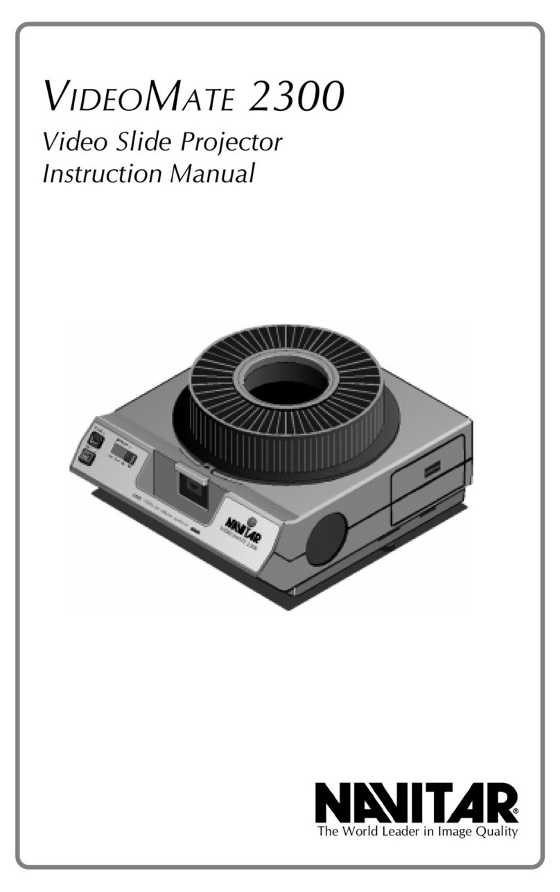
Navitar VideoMate 2300 User manual

Navitar

Navitar VideoMate 2300 User manual

Navitar VideoMate 2250 User manual

Navitar

Navitar VideoMate 2250 User manual

Navitar VideoMate 7500XY User manual

Navitar

Navitar VideoMate 7500XY User manual

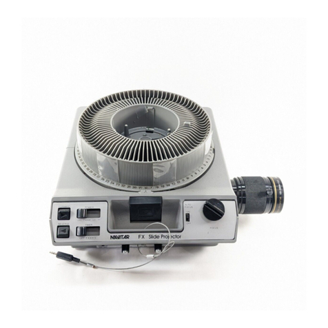
Navitar FX User manual

Navitar

Navitar FX User manual

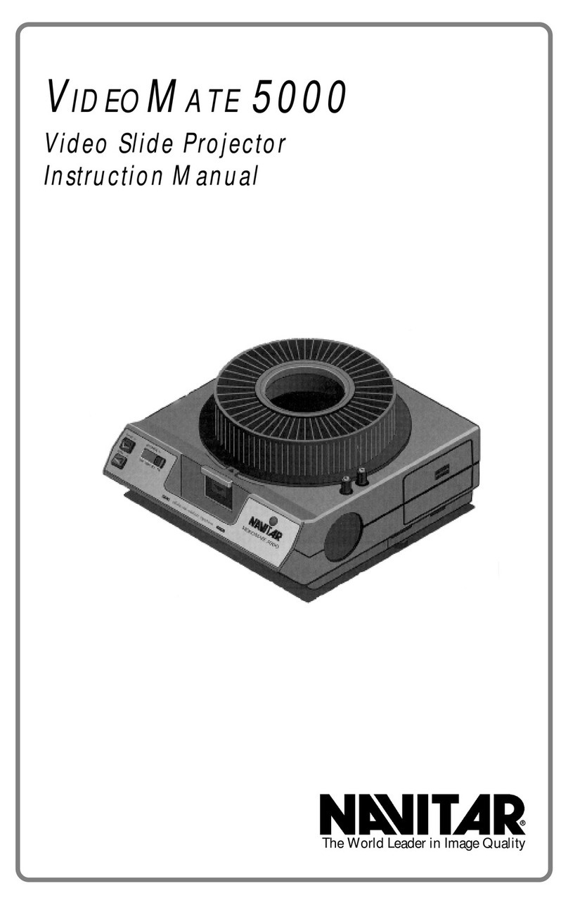
Navitar VideoMate 5000 User manual

Navitar

Navitar VideoMate 5000 User manual

Navitar VideoMate 5000 User manual

Navitar

Navitar VideoMate 5000 User manual

Navitar FX User manual

Navitar

Navitar FX User manual

Navitar VIDEOMATE 2030P User manual

Navitar

Navitar VIDEOMATE 2030P User manual

Navitar 10K User manual

Navitar

Navitar 10K User manual

Popular Projector manuals by other brands

MSC A100 user manual

MSC

MSC A100 user manual

Ricoh Praesepe-PJ1 Series Service training

Ricoh

Ricoh Praesepe-PJ1 Series Service training

Sharp PG-LW3000 Operation manual

Sharp

Sharp PG-LW3000 Operation manual

Sharp XG-PH70X - XGA DLP Projector Setup manual

Sharp

Sharp XG-PH70X - XGA DLP Projector Setup manual

InFocus IN3114 Specifications

InFocus

InFocus IN3114 Specifications

Panasonic PT-LB1 Spec file

Panasonic

Panasonic PT-LB1 Spec file

Toshiba TDP-SW20 Specifications

Toshiba

Toshiba TDP-SW20 Specifications

Toshiba TDP-S3 user manual

Toshiba

Toshiba TDP-S3 user manual

Hitachi CP-S210 series Specifications

Hitachi

Hitachi CP-S210 series Specifications

Sanyo PLC-SW20A Service manual

Sanyo

Sanyo PLC-SW20A Service manual

Sharp PG-M10SU Service manual

Sharp

Sharp PG-M10SU Service manual

Optoma HD33 Operation user's manual

Optoma

Optoma HD33 Operation user's manual

InFocus IN42 Communication Configuration

InFocus

InFocus IN42 Communication Configuration

Hitachi ED-A100 user manual

Hitachi

Hitachi ED-A100 user manual

Cheerlux C50 user manual

Cheerlux

Cheerlux C50 user manual

Runco Quantum Color Q-750d Series Installation & operation manual

Runco

Runco Quantum Color Q-750d Series Installation & operation manual

Epson EMP-7350 owner's manual

Epson

Epson EMP-7350 owner's manual

Ask Proxima C440/C450 user guide

Ask Proxima

Ask Proxima C440/C450 user guide

manuals.online logo
manuals.online logoBrands
  • About & Mission
  • Contact us
  • Privacy Policy
  • Terms and Conditions

Copyright 2025 Manuals.Online. All Rights Reserved.