Navman Qube 300 Guide

1 Installation and Troubleshooting
Guide
Navman Wireless
Installation and
Troubleshooting
Guide
October 22, 2014
Version Number and status: 1.0
Document Date: October 22, 2014
Security Classification: Internal Use Only
Document Owner: Gene Guller

1 Installation and Troubleshooting Guide
2
Table of Contents
1 Installation and Troubleshooting Guide 1
1.1 Introduction 5
1.1.1 Overview 5
1.1.2 Audience 5
1.2 Recommended Installation Practices 6
1.3 Recommended Tools and Supplies 7
1.3.1 Basic Tools 7
1.3.2 Basic Supplies 7
1.4 Qube 300 Hardware 8
1.4.1 Qube 300 Box Contents 8
1.4.2 Qube Installation Supplies Kit (US only) 9
1.4.3 GPS/Cellular Combination Antenna 10
1.4.4 Qube 300 Hardware 11
1.4.5 Qube 300 Security Cover 11
1.4.6 Qube 300 Power Harness 13
1.5 Mounting the Antenna 14
1.5.1 Exposed Install 14
1.5.2 Covert Install 14
1.6 Qube 300 Mounting 15
1.7 Identifying Correct Wires 18
1.7.1 Vehicle's Constant Power wire 18
1.7.2 Vehicle's Ignition wire 18
1.7.3 "Poke &Wrap" Solder-less Connections 20
1.8 Chassis Ground Connection 22
1.9 Mobile Data Terminal: M-Nav 800 23
1.10 ConEx Sensor Monitoring/Auxiliary Devices 25
1.10.1 Digital Inputs DI-1 to DI-4 25
1.10.2 Digital Outputs DO-1 & DO-2 26
1.11 Qube Power Up Procedure 27
1.12 Tamper-Evident Seal 28
1.13 Troubleshooting 29
1.13.1 Qube 300 is not powering up (All LEDs Off) 29
1.13.2 Qube 300 is not reporting in OnlineAVL2 (Cellular Connectivity Issues) 30
1.13.3 Qube 300 is reporting to AVL2 but shows invalid location (GPS Fix Issues) 31
1.13.4 Qube is reporting to AVL2 but displays “Power up + Ignition On” icons. 32
1.13.5 Qube is reporting to AVL2 but does not have any “Ignition Off” events. 32
1.13.6 Qube is reporting to AVL2 but has multiple “Ignition On / Ignition Off” events. 32
1.13.7 Power Cycle/Cold Reset procedure for M-Nav800 33

1 Installation and Troubleshooting Guide
3
1.13.8 Hardware Swap Procedure: determining faulty piece of hardware 33
1.13.9 Power: M-Nav will not power, M-Nav loses power unexpectedly, M-Nav turns
on and off while in use. 33
1.13.10 Messaging: M-Nav can’t send or receive messages 33
1.13.11 Driver ID: Driver Logon function not working 33
1.14 Dimensions and Specifications 34
1.15 Contacts 37

1 Installation and Troubleshooting Guide
4
Disclaimer
It is the Owner’s sole responsibility to install and use the Qube 300 (the Product) in a manner
that will not cause accidents, personal injury or property damage. For the purpose of this
notice, “Owner”, “you” and “your” means the party (including any person authorized by that
party to use and/or install the Product) that has either: (a) purchased the Product; or (b) leased
the Product from Navman Wireless or its related companies.
The Owner of this Product is solely responsible for observing safe driving practices. The choice,
location and installation of all components of the Product is critical. If installation is not correct,
the Product may not perform at its designed potential or specifications. Ensure that any mount-
ing holes that need to be cut in the vehicle will not weaken the vehicle structure or compromise
the safety of the vehicle or its occupants. If in doubt, consult the vehicle manufacturer, or your
Navman Wireless dealer.
TO THE MAXIMUM EXTENT PERMITTED BY LAW, ALL REPRESENTATIONS AND WARRANTIES
(EXCEPT ANY WHICH MAY NOT LAWFULLY BE EXCLUDED) ARE, EXPRESSLY EXCLUDED,
INCLUDING WITHOUT PREJUDICE TO THE, GENERALITY OF THE FOREGOING, THE IMPLIED
WARRANTIES OR MERCHANTABILITY AND FITNESS FOR A PARTICULAR PURPOSE. TO THE
MAXIMUM EXTENT PERMITTED BY LAW NAVMAN WIRELESS DISCLAIMS ALL LIABILITY ARISING
OUT OF OR IN CONNECTION WITH THE PRODUCT (INCLUDING ANY USE OF THIS PRODUCT IN A
WAY THAT MAY CAUSE ACCIDENTS, DAMAGE OR VIOLATE THE LAW).
As Navman Wireless is continuously improving this Product, Navman Wireless may make
changes to the Product at any time which may not be reflected in this document. Please contact
your nearest Navman Wireless office if you require any further assistance.
NAVMAN WIRELESS DISCLAIMS ALL LIABILITY FOR ANY USE OF THIS PRODUCT IN A WAY THAT
MAY CAUSE ACCIDENTS, DAMAGE OR VIOLATE THE LAW.
EMC Compliance
This device complies with Part 15 of the FCC Rules. Operation is subject to the following two
conditions: (1) This device may not cause harmful interference, and (2) this device must accept
any interference received, including interference that may cause undesired operation.
Copyright © 2014
Navman Wireless Holdings L. P. Navman Wireless is a registered trademark of Navman Wire-
less Holdings L. P. All rights reserved. All other trademarks and registrations are the property of
their respective owners.
1 Installation and Troubleshooting Guide
5
1.1 Introduction
1.1.1 Overview
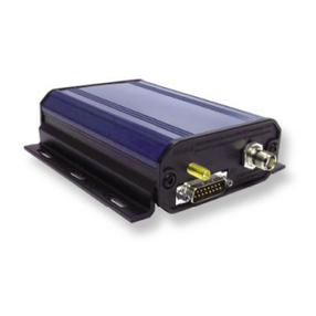
The Navman Wireless Qube 300 is an Automatic Vehicle Location unit (AVL) that is installed
into fleet vehicles. It communicates with a server and allows vehicle information to be stored
and monitored.
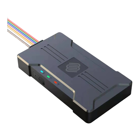
It is a combined GPS (Global Positioning System) and communications product that contains:
la GPS Receiver to provide accurate location data,
la Cellular Modem that enables data to be transferred between the vehicle and the
server,
lan on-board microprocessor to allow data processing and storage, and external com-
munication.
1.1.2 Audience
This Installation Manual is written for a professional vehicle technician.
Navman Wireless welcomes your feedback.

1 Installation and Troubleshooting Guide
6
1.2 Recommended Installation Practices
Review this installation manual to become familiar with all installation procedures and elec-
trical wiring requirements prior to starting the installation. This installation guide has been pre-
pared to provide you with details necessary to complete the Qube installation.
Use of proper tools and testing equipment is required. Never use a grounding style test light.
Use only a Digital Multi Meter (DMM) to test wires in the vehicle. It is strongly recommended
that one of the battery post cables is disconnected or battery disconnect switch is engaged prior
to making electrical connections.
The recommended method of electrical connections for the Qube is by soldering or “Poke and
Wrap”. “Poke and Wrap” is described in detail later in this guide. It is critical to ensure that all
electrical connections are properly insulated with quality electrical tape. Do not use butt con-
nectors, crimp connectors or any other means to connect wires. Failing to ensure proper con-
nections may result in warranty being voided and damage to the Qube and/or the vehicle.
Ensure that all wiring is protected from heat sources and sharp metal edges and is routed in
such manner that it will not get damaged or pinched when vehicle components and trim are
reinstalled. Run new wiring along factory harnesses and secure with quality cable zip-ties. Be
sure to leave a “service loop” near the Qube, enough slack in the wiring to allow working room
and strain relief.
The Qube is NOT waterproof, never mount the Qube in the engine compartment. When mount-
ing the Qube, determine best possible location under the dash and make sure that the Qube
will be securely attached using self-tapping screws or cable zip-ties. Do not force or jam the
Qube into tight places instead of mounting it. When mounting the Qube, do not obstruct any ser-
viceable areas such as fuseboxes, etc. The Qube and its wiring must be mounted away from any
moving parts such as brake, gas, and clutch pedals and linkages.
Follow all safety guidelines outlined in this guide, the applicable Qube Installation Manual as
well as those set forth by industry and government.

1 Installation and Troubleshooting Guide
7
1.3 Recommended Tools and Supplies
1.3.1 Basic Tools
lWire Strippers
lConnector Crimping Tool
lPanel Removal Tool
lDigital Multimeter (DMM)
lT-10S Security Torx Screwdriver
1.3.2 Basic Supplies
lWire Ring Terminals
lCable Zip-Ties
lElectrical Tape
lSpare Fuses (Mini 3A)
lSelf-Tapping Screws

1 Installation and Troubleshooting Guide
8
1.4 Qube 300 Hardware
To ensure professional installation, Navman Wireless provides an install hardware kit for all
new Qube systems.
1.4.1 Qube 300 Box Contents
NOTE: You can use a combi-antenna OR a separate GPS Antenna and a separate Cellular
Antenna.
Contact your Navman Wireless dealer for advice on the best choices for your type of install-
ation and for ordering information, if necessary.

1 Installation and Troubleshooting Guide
9
You may also need the following components, depending on the installation options for the
vehicle:
l8-Wire I/O cable (SAP#10001294)
l10-Wire I/O cable (SAP#10001293)
lNavman Wireless digital temperature probes (and Installation Manual)
lSatellite Modem cable
NOTE: The 3-Wire Power cable, the GPS Antenna, and the Cellular Antenna are the minimal
requirement for tracking only.
1.4.2 Qube Installation Supplies Kit (US only)
To allow for quicker and easier installations, Navman Wireless designed an all-in-one antenna
system that includes both GPS and cellular components built into same housing.

1 Installation and Troubleshooting Guide
10
1.4.3 GPS/Cellular Combination Antenna

1 Installation and Troubleshooting Guide
11
1.4.4 Qube 300 Hardware
1.4.5 Qube 300 Security Cover
Fit the lower part of the security cover from under the cables. Fit the cables for your wiring con-
figuration into the appropriate slots of the lower cover. Angle the upper part of the security
cover onto the front of the Qube over the cables, then push it down in place. The upper part of
the security cover should sit snugly against the lower part with no gap between them. The three
screw holes should align with the screw pillars of the security cover. Insert the two short secur-
ity screws into the screw holes on the outer edges of the Qube 300 , and the long security screw
into the center hole. Tighten all three security screws using a Torx T10 security screwdriver.

1 Installation and Troubleshooting Guide
12

1 Installation and Troubleshooting Guide
13
1.4.6 Qube 300 Power Harness

1 Installation and Troubleshooting Guide
14
1.5 Mounting the Antenna
1.5.1 Exposed Install
Using the attached double-sided tape pad, mount the antenna in the upper or lower corner of
the vehicle’s windshield. Tuck the wires behind the A-pillar panel and run under the dash to the
Qube’s location.
1.5.2 Covert Install
Using the supplied double-sided tape pad, mount the antenna to a flat clean surface under the
passenger side of the dashboard – as high as possible, ideally, just under top dash cover and
positioned horizontally. Make sure the correct side of antenna is facing up, towards the sky.
NOTES:
lDo not mount the GPS antenna under any metal structure or near the vehicle’s radio.
Avoid mounting the antenna under dashboard in areas where metal clipboards, laptops,
loose change, etc may be placed on top of the dash. These items may inadvertently block
the GPS signal to the antenna.
lThe combination antenna is NOT waterproof – do not mount outside of the vehicle.
lThe antenna must be at least 20 cm (8”) from any person to meet FCC RF exposure
requirements.
*Fleet manager will determine the appropriate method (exposed or covert) for mounting the
antenna.

1 Installation and Troubleshooting Guide
15
1.6 Qube 300 Mounting
Attention: The Qube 300 contains an accelerometer that detects vehicle movements. This func-
tionality may be used to track driver behavior on the road. It is critical that the Qube 300 is
mounted securely and cannot move independently of the vehicle OR vibrate off its mounting loc-
ation. Insecure mounting of the Qube 300 may result in false or incorrect vehicle movement
alerts.
The installation location must:
lbe a rigid surface, suitable for your chosen mounting method, where the Qube 300 can
be firmly secured,
lbe dry, Qube 300 is not waterproof,
lallow MDT/M-Nav or other peripheral device connections,
lnot be subject to excessive vibration or excessive heat,
lnot be in plain site or visible to the driver.
lthe physical orientation of the Qube 300 is not important since the accelerometer is self-
calibrating.
The following locations within the vehicle may be suitable:
linside or underneath the dash,
lin the boot/trunk area.
CAUTION
Ensure that any mounting holes that need to be cut in the vehicle will not weaken the vehicle
structure or compromise the safety of the vehicle or its occupants. If in doubt, consult the
vehicle manufacturer.
If mounting holes are required, use grommets to ensure that the vehicle remains waterproof.
3-Wire Basic Tracking & Antenna Connections
The 3-Wire Power cable, a GPS Antenna, and a Cellular Antenna, are the minimal requirements
for tracking only.
Ensure that all cables are:
ltidy and secure, and do not present a hazard to the users of the vehicle/asset,
lprotected from chaffing on sharp edges,
lconnected to manufacturer’s approved points,
llocated where they will not be damaged.

1 Installation and Troubleshooting Guide
16
Pin 3-Wire Colour Function Description
1 Black GND Vehicle Ground/chassis con-
nection.
2 Red +12/24V DC
Main power connection (main
vehicle supply). This connection
must be fused (3 Amp Slow
Blow).
4 Pink Ignition Detect
Positive input from vehicle when
the key is in the IGNITION pos-
ition (not the Accessory position).
This signal must remain ON
DURING engine cranking / star-
tup. This connection must be
fused (3 Amp Slow Blow).
1. Connect the 3-Wire Power cable to the 4-Way PWR connector at position 2.
2. Check that the SIM Card is inserted at position 5.
3. Screw the Cellular Antenna connector to the CELL connector at position 6.

1 Installation and Troubleshooting Guide
17
4. Screw the GPS Antenna connector to the GPS connector at position 7.
5. Secure both antenna connectors using an open-ended 8mm spanner.
Complete the installation by securing all wires with zip-ties, away from any moving parts or
sharp metal edges.
Reconnect any of the vehicle’s connectors that were unplugged during disassembly and replace
all interior trim panels.

1 Installation and Troubleshooting Guide
18
1.7 Identifying Correct Wires
1. Remove any interior/under dash trim panels necessary to gain access to vehicle’s wiring.
2. Attach fuse holders to the Constant (Red) and the Ignition (Pink) wires of the Qube’s
power harness.
3. Navman Wireless recommends locating and sourcing constant power and ignition con-
nections at the ignition key wiring harness located behind ignition key cylinder.
NOTE: If the ignition switch harness is not accessible, or amperage restriction exists, or
the vehicle has an electronic starting system, Qube’s constant power and ignition con-
nections can be made at the interior fusebox.
4. Use a multimeter and the chart on next page to identify Constant and Ignition wires.
1.7.1 Vehicle's Constant Power wire
The correct source wire will have battery voltage present at all times, even when the ignition
key is in off position or removed. Connect Qube’s red wire here.
1.7.2 Vehicle's Ignition wire
The correct source wire will have voltage present when the ignition key is in turned to the ON
position, during crank/start and then while motor is running. Connect Qube’s pink wire here.

1 Installation and Troubleshooting Guide
19
NOTES:
lAfter appropriate wires have been identified, it is strongly recommended that one of the
battery post cables is disconnected prior to making wire connections.
lIf the vehicle has a master battery disconnect switch, Qube’s power must be sourced at
the battery or the hot side of the master battery disconnect switch.

1 Installation and Troubleshooting Guide
20
1.7.3 "Poke &Wrap" Solder-less Connections
The recommended method of connecting wires is by soldering. As an alternative, when working
inside the cab or any weatherproof environment, a “Poke & Wrap” method for solder-less con-
nections will be acceptable.
NOTE: During the “Poke & Wrap” procedure use extreme caution not to allow any exposed
wires to come into direct/indirect contact with the vehicle’s chassis or other exposed wires. It is
recommended to disconnect vehicle’s battery when making electrical connections.
1. Strip Use wire stripping tool to remove about ¾ inch of insulation from the source wire in
the vehicle. Next, strip about 1” of insulation from your fuse holder’s wire.
2. Poke Use a sharp tool to divide exposed strands of the source wire down the middle, cre-
ating a gap.
3. Insert . Insert fuse holder’s stripped wire through the gap in the source wire. Squeeze the
gap shut.
4. Twist Tightly twist exposed lead of the fuse holder around the bare section of vehicle’s
source wire (4-6 turns).
5. Lock Bend the fuse holder wire back onto the wrapped section. This step will act as the
lock for the Poke & Wrap type of wire connection.
6. Secure Apply adequate amount of electrical tape to isolate your connection. Wrap
tightly. Finally, use a zip-tie to completely secure the connection. This will ensure the con-
nection will not vibrate loose over time. Apply tamper seal.
Other manuals for Qube 300
1
Table of contents
Other Navman GPS manuals

Navman
Navman W300 User manual

Navman
Navman EZY series Instructions for use

Navman
Navman ICN 550 User manual

Navman
Navman MY Series User manual

Navman
Navman M-Nav 760 User manual

Navman
Navman S-Series User manual

Navman
Navman Qube3 Installation guide

Navman
Navman GPS 4400 User manual

Navman
Navman S-Series Instructions for use

Navman
Navman F15 User manual

Navman
Navman F10 User manual

Navman
Navman EZY Advanced Instructions for use

Navman
Navman F37M User manual

Navman
Navman EZY User manual

Navman
Navman Sport Tool M300 User manual

Navman
Navman N60i User manual

Navman
Navman M-Nav 760 User manual

Navman
Navman LA000507 User manual

Navman
Navman 8084 User manual

Navman
Navman 8084 User manual