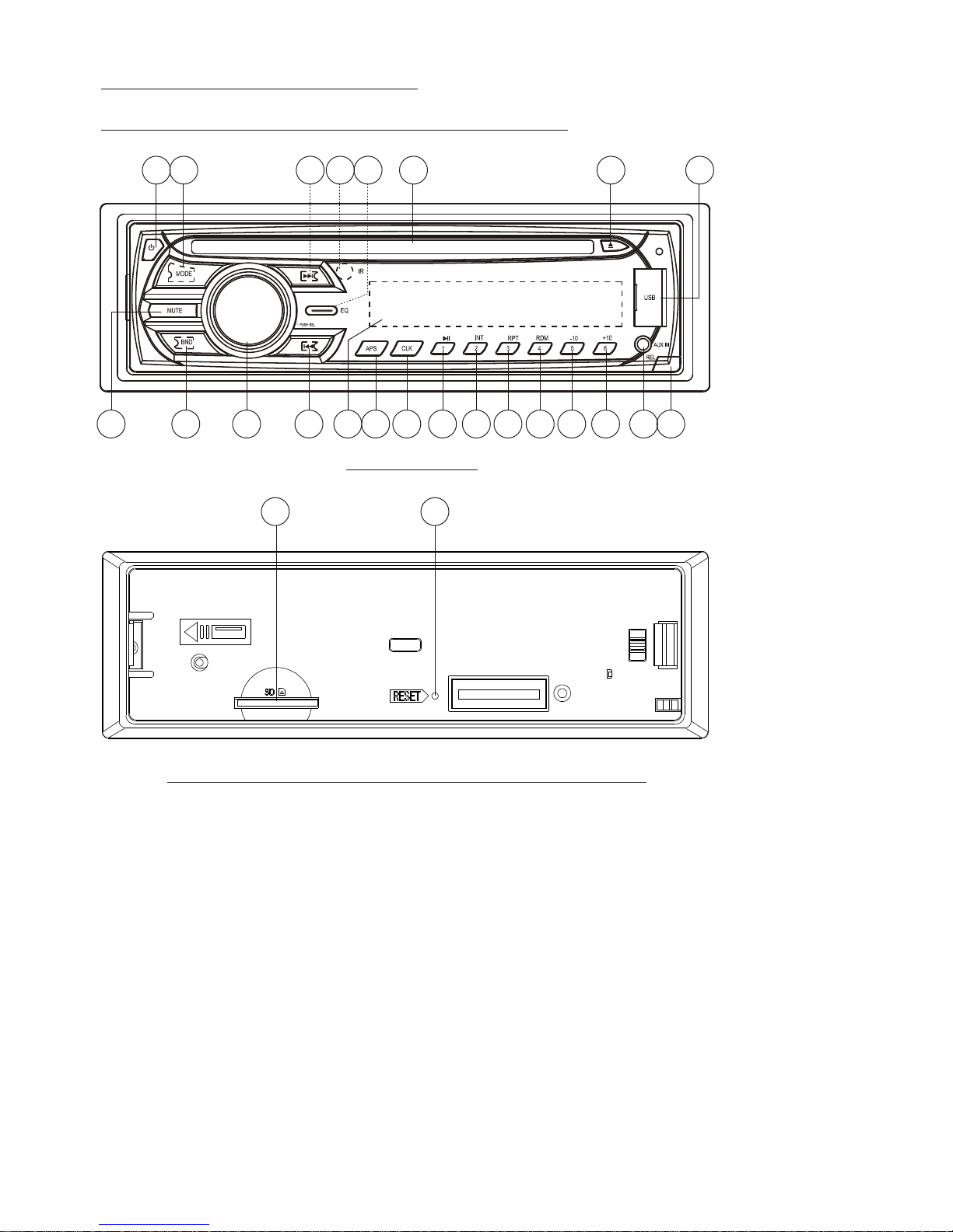
manuals.online logo
Brands
  1. Home
  2. •
  3. Brands
  4. •
  5. Naxa
  6. •
  7. Car Receiver
  8. •
  9. Naxa NCA-604 User manual

Naxa NCA-604 User manual

Other manuals for NCA-604

1

Other Naxa Car Receiver manuals

Naxa NCD-702 User manual

Naxa

Naxa NCD-702 User manual

Naxa NCA-683 User manual

Naxa

Naxa NCA-683 User manual

Naxa NCA-699 User manual

Naxa

Naxa NCA-699 User manual

Naxa NCD-701 User manual

Naxa

Naxa NCD-701 User manual

Naxa NCA-607 User manual

Naxa

Naxa NCA-607 User manual

Naxa NCA-678 User manual

Naxa

Naxa NCA-678 User manual

Naxa NCA-611 User manual

Naxa

Naxa NCA-611 User manual

Naxa NCD-691 User manual

Naxa

Naxa NCD-691 User manual

Naxa NCD-650 User manual

Naxa

Naxa NCD-650 User manual

Naxa NCA-676 User manual

Naxa

Naxa NCA-676 User manual

Naxa NCA-670 User manual

Naxa

Naxa NCA-670 User manual

Naxa NCA-602 User manual

Naxa

Naxa NCA-602 User manual

Naxa NCD-650 User manual

Naxa

Naxa NCD-650 User manual

Naxa NCA-613 User manual

Naxa

Naxa NCA-613 User manual

Naxa NCA-615 User manual

Naxa

Naxa NCA-615 User manual

Naxa NCA-675 User manual

Naxa

Naxa NCA-675 User manual

Naxa NCA-600 User manual

Naxa

Naxa NCA-600 User manual

Naxa NCA-608 User manual

Naxa

Naxa NCA-608 User manual

Naxa NX-671 User manual

Naxa

Naxa NX-671 User manual

Naxa NCA-603 User manual

Naxa

Naxa NCA-603 User manual

Naxa NCA-671 User manual

Naxa

Naxa NCA-671 User manual

Naxa NCA-649 User manual

Naxa

Naxa NCA-649 User manual

Naxa NCA-677 User manual

Naxa

Naxa NCA-677 User manual

Naxa NCA-605 User manual

Naxa

Naxa NCA-605 User manual

Popular Car Receiver manuals by other brands

Linear Series LS5050 Operation and installation manual

Linear Series

Linear Series LS5050 Operation and installation manual

Kenwood KRC-160 instruction manual

Kenwood

Kenwood KRC-160 instruction manual

Sony XR-CA430X Service manual

Sony

Sony XR-CA430X Service manual

T+A Elektroakustik K1 CD-RECEIVER operating instructions

T+A Elektroakustik

T+A Elektroakustik K1 CD-RECEIVER operating instructions

SoundMax SM-CDM1052 instruction manual

SoundMax

SoundMax SM-CDM1052 instruction manual

Xtrons HD107HD user manual

Xtrons

Xtrons HD107HD user manual

Mopar RB3 manual

Mopar

Mopar RB3 manual

Clarion ADDZEST DMZ615 owner's manual

Clarion

Clarion ADDZEST DMZ615 owner's manual

Sony XAV-601BT Specifications

Sony

Sony XAV-601BT Specifications

PIE GM12-POD/S Operation manual

PIE

PIE GM12-POD/S Operation manual

Hyundai H-910H instruction manual

Hyundai

Hyundai H-910H instruction manual

Sony XR-C6100 Service manual

Sony

Sony XR-C6100 Service manual

Sony CDX-L600X - Fm/am Compact Disc Player Installation/connections

Sony

Sony CDX-L600X - Fm/am Compact Disc Player Installation/connections

Motorola VWA63 Service manual

Motorola

Motorola VWA63 Service manual

Sound Storm STM93R user manual

Sound Storm

Sound Storm STM93R user manual

Nextar D3201 instruction manual

Nextar

Nextar D3201 instruction manual

Alpine CDE-163BT owner's manual

Alpine

Alpine CDE-163BT owner's manual

Kenwood KDC-X303 quick start guide

Kenwood

Kenwood KDC-X303 quick start guide

manuals.online logo
manuals.online logoBrands
  • About & Mission
  • Contact us
  • Privacy Policy
  • Terms and Conditions

Copyright 2025 Manuals.Online. All Rights Reserved.

-1-
Content
Installation steps...........................................................................
General information about remote control......................................
1. Removing insulating sheet.........................................................
2. Replacing the lithium cell...........................................................
3. Note about using the remote control...........................................
4. Warning about lithium cells of remote control.............................
Locations and Names of controls...................................................
1. Locations and Names of controls on main unit............................
2. Locations and Names of controls on remote control...................
General operation...........................................................................
Radio operation.............................................................................
Disc/USB/card operation............ ...................................................
1. Loading or unloading a disc, USB or card..................................
1.1 Loading a disc, USB or card.....................................................
1.2 Unloading a disc, USB or card..................................................
2. Function of controls on main unit or remote control..................
AUX IN operation...........................................................................
Troubleshooting............................................................................
Specifications...............................................................................
2
6
6
6
6
6
7
7
8
9
10
11
11
11
11
12
14
15
16
INSTALLATION STEPS
1. Remove 2 screws for protecting deck;
1) Remove chassis from the Slide Bracket Housing as follows:
2) Remove 2 screws protecting the deck as
right;
2. Connecting all wires
1) Slide Bracket Housing;
2) Remove the control panel from the chassis as follows:
A. Press REL button to detach the control panel .
B. Hold the right end of the control panel to pull rightward
illustrated on the
Re-insert the chassis into the
a little and then remove it
REL button
PLASTIC TRIM OUT
KEY PLATE
KEY PLATE
If you want to remove the chassis from the Slide Bracket Housing , first remove the
Plastic trim from both sides, then insert 2 Key Plates into the left and the right side of
the chassis as illustrated.
-2-
-3-
3) Connect all wires as follows:
RADIO ANTENNA JACK FRONT AUDIO OUT RCA JACK R (red)
FRONT AUDIO OUT RCA JACK L (white)
REAR AUDIO OUT RCA JACK L (white)
REAR AUDIO OUT RCA JACK R (red)
The Description of the Fixed ISO Female Connector
CONNECTOR A
1.
2.
3.
4. Memory +12V
5. Auto Antenna
6.
7. 12V (To Ignition Key)
8. GROUND
CONNECTOR B
1. Rear Right Speaker (+)
2. Rear Right Speaker (-)
3. Front Right Speaker (+)
4. Front Right Speaker (-)
5. Front Left Speaker (+)
6. Front Left Speaker (-)
7. Rear Left Speaker (+)
8. Rear Left Speaker (-)
FUSE
Fixed ISO Female Connector
4) Attaching the control panel onto the chassis.
A. Align and thrush the bulge of the control panel into the hollow of the chassis.
B. Push the right end of the control panel to the chassis till a click sound is heard.
* How to clean panel connector
Frequent detachment will cause the panel connectors to deteriorate. To minimize
deterioration, periodically wipe the panel connector with a clean/soft/dry cloth .
5) Test to make sure that it works properly.
3. Instal the main unit according to the installation diagram on the next page:
1) Mount the main unit in A/V position in vehicle.
2) Bend tabs of the sliding metal housing where necessary to ensure that
the front part of main unit is fixed;
3) Use a metal strap to fix the rear part of the chassis.
* Uninstalling the main unit:
1) Remove the metal strap from the main unit;
2) Remove the plastic trim frame from the main unit;
3) Insert a key plate into the left and the right side of the main unit and draw the
main unit out of the sliding metal housing.
Bulge
Hollow
Panel Connector
-4-
-5-
Installation diagram
DASH BOARD
METAL MOUNTING
STRAP
HEX NUT
SPRING WASHER
PLAIN WASHER
TAPPING SCREW
CONSOLE
SLIDE BRACKET
HOUSING
HEX BOLT
-6-
General information about the remote control
1. Removing insulating sheet
The remote control comes with an insulating
sheet attached to the underside of the remote
control as illustrated on the right
The remote control is disabled and will not work
until the insulating sheet is removed.
as illustrated on the right
.
2. Replacing the lithium cell
If the electric energy of the lithium cell is weak,
replace it .
1. Press and hold the movable block in the
direction indicated by arrow 1 , at the same
time pull the cell holder out of the remote control
in the direction indicated by arrow 2 .
2. Replace the old cell with a new one with (+)
polarity side upward .
3. Insert the cell holder into the remote control again.
3. Note about using the remote control
1. Face the emitting window of the remote control towards the sensor window of
the unit.
2. Operation angle for front panel: About 30 degrees
3. The distance between the emitting window of the remote control and the sensor
window of the unit : < 5M .
4. Warning for lithium cells of remote control
leakage may cause damage to remote control.1.Cell
2.Do not throw cells into fire, it may cause an explosion.
3.To avoid accidents, keep cells out of reach of children.
Locations and Names of controls
1. Locations and Names of controls on main unit
-7-
1823
1. REL button
2. PWR button
3. SEL button and VOL knob
4. BAND or ID3 button
5. EQ button
6. APS button
7. MUTE button
8. >|| or 1 button
9. INT or 2 button
10.RPT or 3 button
11.RDM or 4 button
12.-10 or 5 button
13.+10 or 6 button
14. |<< button
15. >>| button
16. MODE button
17. EJECT button
18. RESET button
19. IR sensor window
20. AUX IN jack
21. USB port
22. LCD screen
23. Card slot
24. CLK button
25. Disc slot
Control Panel
Front side of chassis after removing control panel
2
31
76 9814
15 17
19
20
21
22
25
4
5
10 11 12 13
16
24
2. Locations and Names of controls on remote control
-8-
PWR
MUTE
VOL-
SEL
ENTER
LOUD
VOL+
ST
MO
LOC
DX
MOD DISP
ID3
BAND
APS
SEARCH
SCAN
123
456
/TOP
INT
-10
RPT
RDM
+10
1
2
3
5
6
8
9
11
4
7
10
12
13
14
15
16
17
18
19
20
21
1. PWR button
2. < button
3. LOUD button
4. VOL- button
5. LOC/DX button
6. ID3 or BAND button
7. APS or SEARCH button
8. >|| or TOP or 1 button
9. RDM or 4 button
10.INT or 2 button
11. VOL+ button
12. MUTE button
13. SEL or ENTER button
14. > button
15. ST/MO button
16. DISP button
17. MODE button
18. SCAN button
19. RPT or 3 button
20. +10 or 6 button
21. -10 or 5 button
General Operation
1. PWR button
To power main unit on or off.
2. VOL knob or VOL+ & VOL- button
To increase or decrease volume level.
3. MUTE button
To cancel or resume sound.
4. SEL button
5. EQ button
To select a desired preset EQ mode from POP, ROCK, CLASSIC, FLAT and OFF.
6. LOUD button
To switch LOUD mode on or off.
7. DISP or CLK button
To display clock time, briefly press the DISP or CLK button.
To set clock time, first long press the DISP or CLK button to flash hour, and rotate
the VOL knob or press the VOL+ or VOL- button to adjust the hour; then briefly
press the SEL button to flash minute, and rotate the VOL knob or press the VOL+
or VOL- button to adjust the minutes; finally press the DISP or CLK button to con-
firm it.
8. MODE button
To switch on a work source between RADIO, DISC, USB, CARD and AUX IN.
9. REL button
To detach the control panel from chassis.
10. RESET button
To reset all parameters to factory default values.
* When LCD does not display normally or sound is distorted or some controls are
disabled, press the REL button to detach the control panel from chassis and re-
move the control panel from the chassis, then use a subject with a sharp point
end to thrush the RESET hole.
To switch between BAS(bass), TRE(treble), BAL(balance), FAD(fader), EQ,
BEEP, LOUD, MONO/STEREO(in radio mode), LOC/DX(in radio mode) and
VOL(volume), press the SEL button repeatedly. After selecting a desired mode,
rotate the VOL knob or press the VOL+ or VOL- button to set it.
-9-