NBB Nano-M SMJ User manual

Receiver Type /
Version
Factory No.
Frequency
Transmitter Type /
Version
Factory No.
Frequency
Operating instructions
Nano-M SMJ USA/Canada
Compact-M
RADIO CONTROL SYSTEMS
OTTO-HAHN-STR. 3 - 5
INTERNET: www.nbb.de
TEL.: +49(0)7237/ 999-0
FAX: +49(0)7237/ 999-199

Table of contents
General information
Transmitter Nano-M SMJ
Receiver Compact-M
Accessories
Technical documents
1
2
4
10
13
17

The transmitter and receiver type, serial number, frequency range and approval for non-
EU countries are specified on the nameplates.
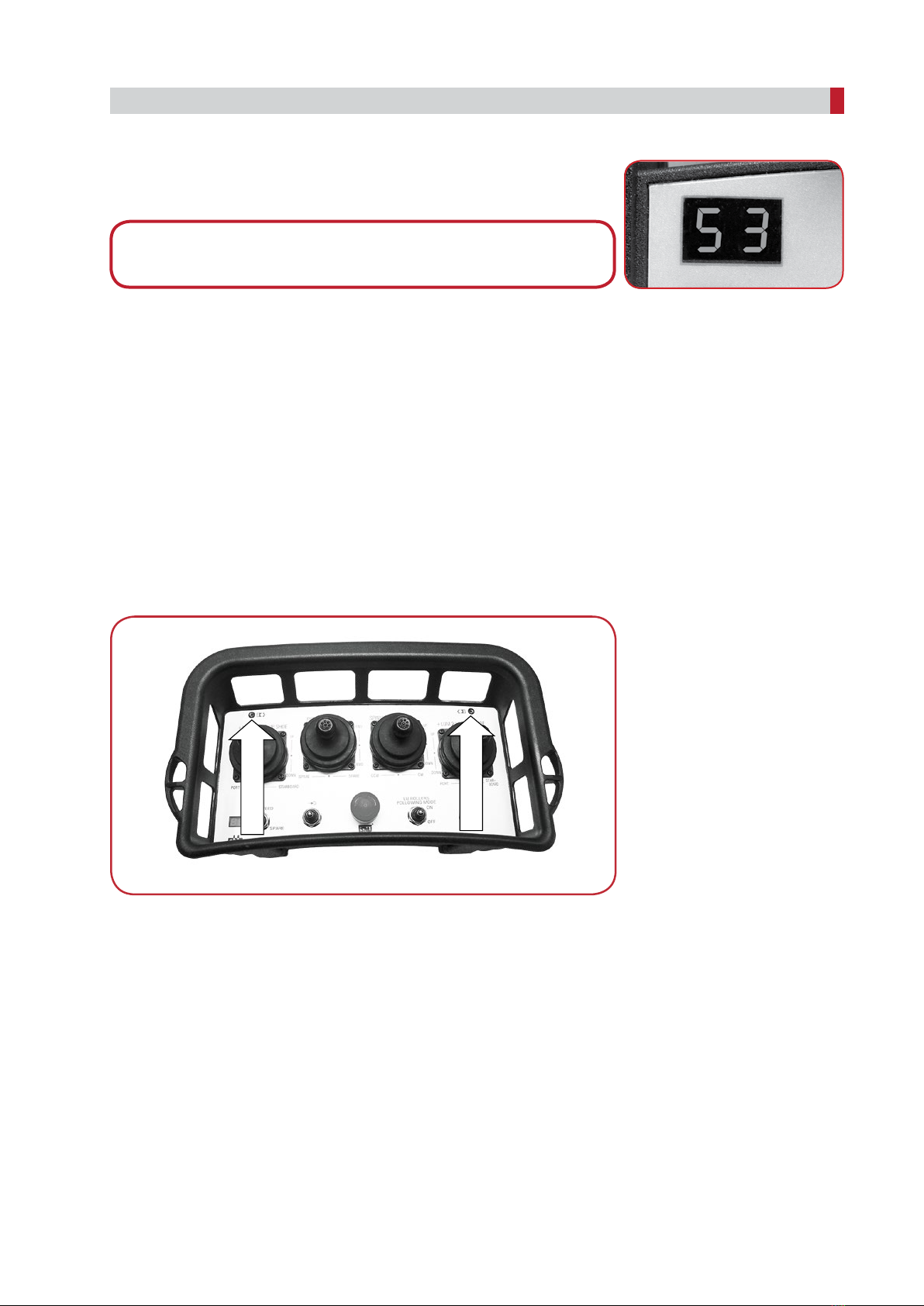
Please always specify the serial number for queries.
Example:
Never expose the radio control system to a strong jet from high pressure
cleaning equipment!
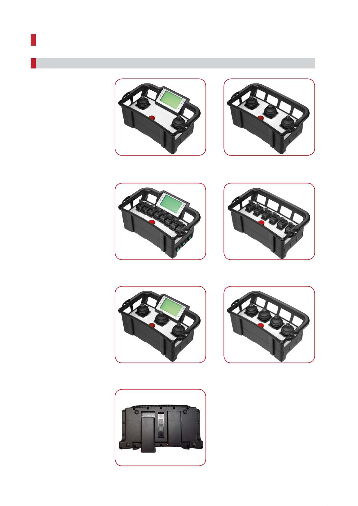
nTransmitter including carrying system
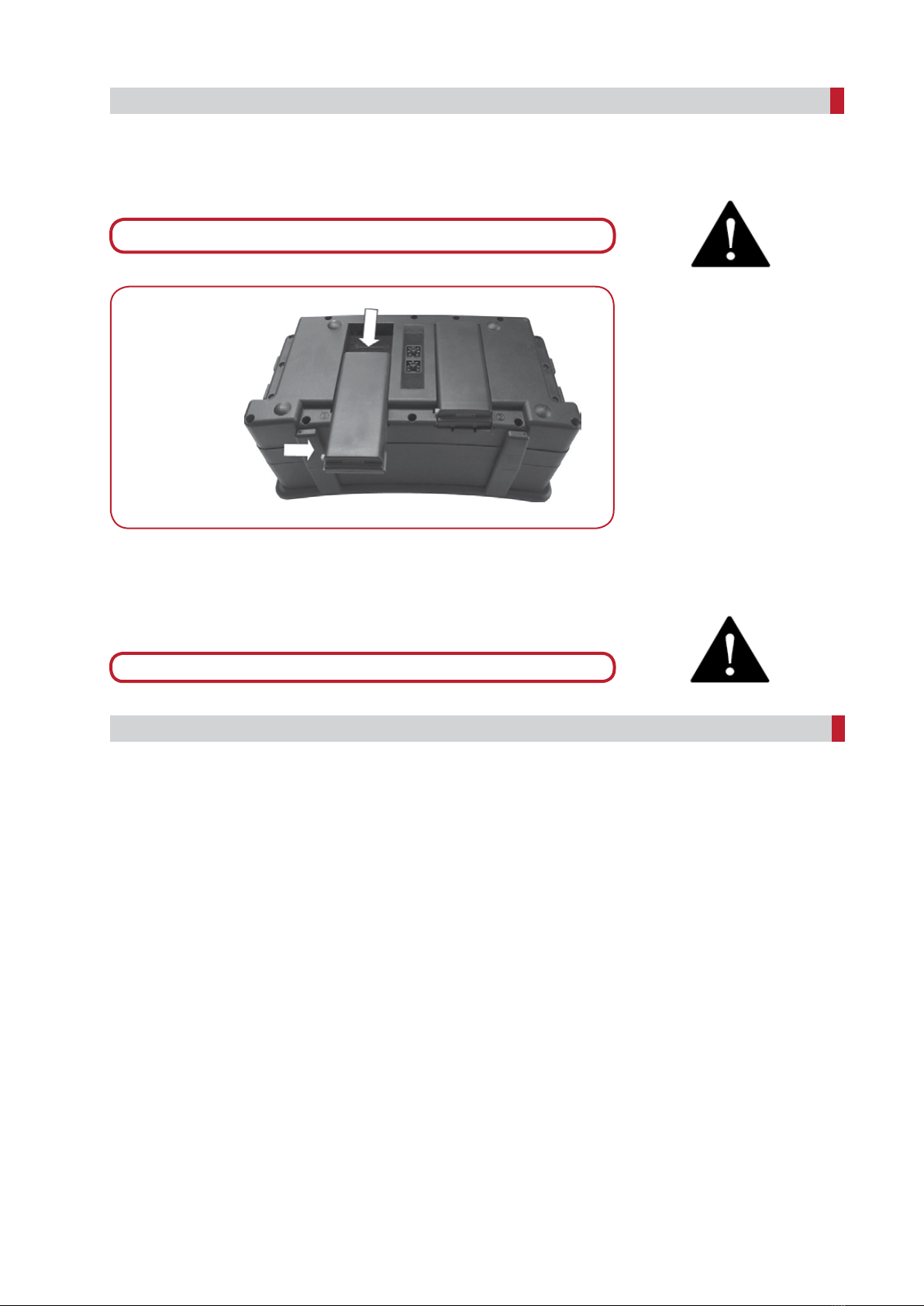
nReceiver with integrated mounting holes
nConnection cable for the receiver
The order confirmation and/or the delivery note when the system is received
is binding for the actual scope of delivery.
Even if you have already operated radio control systems, always read these
operating instructions before commissioning. Only these operating instructions
include the latest information about your NBB radio control system.
Please refer to the enclosed documents for explanations about the operating license.
Always observe the relevant work safety and accident prevention regulations. Only
trained and authorised persons may operate the NBB radio control system. The safety
features installed in the NBB radio control system must be checked regularly.
The NBB radio control system must be shut down immediately if there are
any faults. The transmitter must be switched off using the EMERGENCY STOP
switch or the STOP key. The connection cable must be disconnected at the
receiver of the connection socket (terminal) of the controlled system. The
radio control system may only be repaired by NBB or specialists authorised
by NBB.
Disregard of these recommendations puts you and others in danger! NBB refuses any
warranty or liability in such cases. This radio control system is only suitable for the
control of construction machines and industrial systems. The applied safety measures
(EMERGENCY STOP, zero position) are only fully effective in this application area. Any
different use is not permitted and releases NBB from any responsibility.
Transmitter Type / Version:
Factory No.:
Frequency:
Nano-L SMJ
999 899 4990
402 -470 MHz
x
Receiver Type / Version:
Factory No.:
Frequency:
Compact-V
999 899 4990
402 -470 MHz
x
Standard scope of delivery
Safety information
Nameplates
2
General information

Your NBB radio control system is maintenance-free to a large extent. Nevertheless
observe the following points:
nRegularly check the EMERGENCY STOP and STOP function.
nRemove remnants of building material.
nDisconnect receiver from the power supply for arc welding work, otherwise there
is a risk of damage to the receiver electronics.
nRegularly check wear parts.
NBB grants a functional warranty of 12 months from the date of sale on all NBB radio
control systems (transmitter, receiver, charger). Working hours and material costs are
included in the warranty. Shipping costs shall be at the expense of the buyer. Wear
parts, relays, rechargeable batteries and batteries are excluded from the warranty.
The functional warranty will become null and void for damage, accidental damage,
negligence, improper use, non-compliance of the operating conditions, non-observance
of the operating, test and service information as well as for repairs or device
modifications that are not authorised by NBB.
NBB is not liable for indirect damage and reserves the right to decide on improvements
or replacements.
If a fault event occurs with the NBB radio control system, cease work immediately!
Please note that even small faults can represent the beginning of extensive defects.
Always contact your dealer or NBB in the event of a fault. Do not attempt to repair the
NBB radio system yourself, irreparable damage may occur.
Maintenance
Warranty
In the event of faults
3

4
Variations
Transmitter Nano-M SMJ
Nano-M SMJ with a display and
2 joysticks
Nano-M SMJ with 3 joysticks
Nano-M SMJ with a display and
8 joysticks
Nano-M SMJ with 6 joysticks
Nano-M SMJ with a display and
3 joysticks
Nano-M SMJ with 4 joysticks
Nano-M SMJ 7.2 V accumulator
system

Operating voltage 7.2 V:
Insert the battery in the battery compartment for commissioning.
For removal, press in the locking pin to unlock and slide out the battery to the side.
If the NBB radio control system is not to be used for a long time, it is strongly
recommended to charge the battery approx. every 4 weeks. This prevents deep
discharge of the battery and enhances its service life. If you decommission the
NBB radio control system for a long time, we recommend that you remove the
batteries from the transmitter!
Safety equipment in the NBB radio control system:
nEMERGENCY STOP or STOP function
nZero position interlock
nAddressing each transmitter using a unique bit combination
nRubber sleeves to protect the switch
Please check the sleeves and the housing for breaks and cracks each time before
commissioning the transmitter. Contact your service team if necessary. Non-observance
can cause malfunctions and water damage.
Commissioning
Safety equipment
5
Press in the locking pin
and slide out the battery
Please refer to the technical annex for the exact design.
Completely charge the rechargeable battery before initial use.

Switching the transmitter on and off
Design with emergency stop
Unlock the Emergency Stop pushbutton by turning clockwise to switch on the
transmitter.
Two short signals can be heard.
A red dot flashes in the LED display and an antenna symbol appears in the LC display
during operation.
The transmitter is switched off by pressing the Emergency Stop pushbutton once.
After pressing the EMERGENCY STOP switch, stop telegrams are sent for 2 seconds
to switch off the system. This shut-off time is displayed on the LED display by the
segments rotating clockwise.
Toensurefaultlessoperation,pleaseobservethefollowingrulesforoperation precisely:
The system to be controlled - provided the transmitter is ready for operation - can only
be switched on if no command transmitters are activated. The command necessary
for this is activated by the «On/Horn» key. Here a horn signal is triggered for the
system to be controlled. After switching on the system to be controlled, this key
is used, according to the work specifications, for repeated triggering of the horn
signal.
Frequency switching:
To switch the frequency, press and hold the «On/Horn» key. Now press the «Frequency
switching» key successively. If the receiver locks on a new frequency, a horn signal can
be heard and the system is ready for operation.
Please observe the country-specific regulations, if applicable.
The system can also be equipped with automatic frequency switching (LBT) as an option.
Operation of the system
6
Operation:
The red dot flashes.
FREQUENCY
SWITCHING
ON/HORN
FREQUENCY SWITCHING

7
Channel number:
During operation, the set channel can be displayed by pressing the «Frequency swit-
ching» key.
Operation of the system
Please refer to the technical annex for the exact position of the «On/Horn» and
«Frequency switching» keys.
Battery life warnings:
The LED display of the active battery flashes green during operation. When the control
lamp flashes orange, the battery indicates a remaining capacity of approx. 10%. The de-
pletion of the battery capacity is indicated by the red control lamp lighting up. To replace
the depleted battery place the system on a solid, level surface with access to the bottom
at the system. Remove the spent battery and replace with a fully charged battery. The
radio system will not have an interruption in contol during battery replacement provided
the second battery is installed and has capacity left. Only charge the discharged battery
in the charger.
Battery display:
LED - flashes green: Battery OK and in operation.
LED - flashes orange: Battery capacity left around 10%.
LED - flashes red: Battery capacity left around 5%.
LED - permanently lights up red: Battery empty, transmitter switches to
2nd battery.
Energy saving function:
If no keys are pressed within a specified time*, the transmitter automatically switches
off. The red dot in the LED display goes out.
A transmitter can also be manufactured without a standby function for continuous
operation as an option.
*The standby time can be set as desired.
LED battery left
LED battery right

8
Changing the Surface Mounted Joystick:
Switch off the transmitter and remove the batteries.
Loosen all 4 screws of the Surface Mounted Joystick with a Torx 10 screwdriver and
remove the screws.
Remove the Surface Mounted Joystick from the top.
Insert the new Surface Mounted Joystick and make sure that the plugs and sockets
are above each other. Screw down the Surface Mounted Joystick with the 4 screws
previously removed and reinsert the batteries.
Start teach mode after changing the Surface Mounted Joystick.
Surface Mounted Joystick teach mode activation with pushbutton:
n
1.
2.
3.
4. .
5.
6.
7.
n
Technology SMJ - Surface Mounted Joystick
1
6
42
55
3
To activate teach mode, the transmitter must be switched off.
Press and hold the «Frequency switching» key.
Switch the transmitter on.
The letters «Jt» appear in the display after 2 seconds.
Now release the «Frequency switching» key.
Completely move the Surface Mounted Joystick in one direction and return it to
the 0-position. Repeat this for all directions. Perform point 5 for all other Surface
Mounted Joystick if required. Reactivation of teach mode is not required.
Press the «On/Horn» key once. Teach mode will be closed and the new Surface
Mounted Joystick will function as intended by the system design.
Attention! The transmitter is now in working mode!
Error: If «Jt» does not appear in the display, please switch off the transmitter and
start teach mode activation from the beginning!

9
Surface Mounted Joystick teach mode activation with pushbutton and display:
n
1.
2.
3.
5.
6.
7.
n
The TEACH MODE, memory of max. and min.-values of the valves adjustment with
proportional control, is activated by a separate combination of keys.
Please refer to the technical annex.
Nano-M SMJ
See nameplate
Switchable frequency to respective national band possible as a result of synthe-
sizer technology.
Addressing each transmitter using a unique bit combination
FSK - Signal acc. to CCITT V.23
1200 -9600 baud (bit / sec.)
Approx. 300 - 1000 m (depending on environment)
Accumulateur 7.2 V NBB
60 - 100 mA
<10 mW ERP
IP 65
From -20 to +65 °C
3500 g
354 x 229 x 141 mm
Technical data
Transmitter
Transmission frequency range
Data security
LF-modulation
Baud rate
Range
Operating voltage
Current consumption
RF output
Protection class
Operating ambient temperature
Weight (without battery)
Measurements (L x W x H)
Technology SMJ - Surface Mounted Joystick
55
3
1
6
42
To activate teach mode, the transmitter must be switched off.
Press and hold the «Frequency switching» key.
Switch the transmitter on.
«Joy Teach» with graphics appears in the display after 2 seconds.
Now release the «Frequency switching» key.
Completely move the Surface Mounted Joystick in one direction and return it to
the 0-position. Repeat this for all directions. Perform point 5 for all other Surface
Mounted Joystick if required. Reactivation of teach mode is not required.
Press the «On/Horn» key once. Teach mode will be closed and the new Surface
Mounted Joystick will function as intended by the system design.
Attention! The transmitter is now in working mode!
Error: If «Joy Teach» does not appear in the display, please switch off the transmitter
again and start teach mode activation from the beginning!

10
Variations
Receiver Compact-M
Compact-MA Compact-MB
Compact-MC Compact-MD

Commissioning
Mounting instruction
Function control
11
The receiver is connected via a connection cable to the system to be controlled. Please
observe the instructions of the system manufacturer when installing.
We strongly recommend establishing this connection via a central, easily
accessible plug connection (e.g. Tyco type (HTS) plug connection, series HE/
HB/HN/ HA, or a comparable one from a different manufacturer) to enable
a fast and precise error diagnosis for servicing and to be able to remove the
receiver without installation work.
The power for the receiver is supplied via the connection cable in most cases.
In general a ground cable (neutral conductor) must be installed for systems that have
never been operated with a radio control system. Otherwise the power for the receiver
electronics cannot be supplied! Please make sure that the operating voltage of the
receiver corresponds with the connection values of the system to be controlled. The
valid operating voltage is noted in the Annex.
A regular system test of the NBB radio control system is necessary for the maintenance
of operational safety. For single shift operation, we recommend performing this control
at least once a week. The control can be performed with the aid of the control lamps
located on the receiver. For this purpose, the transmitter must be ready for operation.
Only mount the receiver vertically to the external wall of the switch cabinet and make
sure that the antenna protrudes above the wall.
Make sure that the antenna is not partially or completely shielded by metal parts.
For installation in the cabin or switch cabinet, the antenna is installed on the outside
using the extension cable and attached with the mounting bracket as horizontal as
possible at a distance to the metal parts to be shielded.
The antenna should always be mounted so that it remains visible every time the loca-
tion of the transmitter is changed.
Falsch
Richtig
Falsch
.
Richtig
Installation for rotating tower crane. Mount antenna with extension cable horizontally for
rotating tower crane
RIGHT
WRONG
WRONG RIGHT
Above all make sure that no-one is in the danger zone. Risk of accident!
Only switch the receiver on - the transmitter should remain switched off.
Put the transmitter into operation by pressing the “START/ON/HORN” key.
Now check the commands (always start with the lowest level) and the correct
response of the system to be controlled.
STOP control. Press the STOP key on the transmitter. Afterwards check whether
the system to be controlled performs the stop operation sequence, i.e. whether it
switches off (shutoff time depends on application).

Meaning of the LED display on the Compact-M:
Receiver connect to power, without communication with transmitter:
1. LED constant ON (green)
2. LED flashing irregular (orange) -> receiver searching transmitter
Connect to transmitter:
1. LED flashing regular (green)
2. LED flashing regular (orange) -> communication ok
1. LED flashing irregular (green)
2. LED flashing irregular (orange) -> Interference on RF signal
-> (change frequency)
1. LED flashing regular in 1 sec. interval (red) -> Emergency relay fault.
2. LED flashing regular (orange)
Receiver Compact-M with charger (optional):
3. LED flashing regular (yellow) -> battery charging
3. LED constant ON (yellow) -> battery full charged
Service connector: Only for NBB service team.
If problems arise:
1. Check whether the transmitter is switched on.
2. Check the power supply of the receiver.
3. (optional) Check or change the current frequency channel.
Function control
Technical data
12
Receiver
Receive frequency range
Data security
Safety
Contact load of EMERGENCY STOP
relay
Contact load of relay
Power consumption
Supply
Operating ambient temperature
Protection class
Weight
Measurements (L x W x H)
Compact-M
See nameplate
Addressing each receiver by a separate, unique combination >16 million options
EMERGENCY STOP with self-test
Restart lockout in the event of a faulty EMERGENCY STOP relay
Max. 4 A; 12 V/24 V DC
Max. 6 A; shortcircuit-safe; analog PWM or digital 12 V/24 V DC
<4 VA / 12 V DC; <3 VA / 24 V DC depending on the number of active relays
Please refer to the technical documents
From -20 to +70 °C
IP 65
Approx. 1100 g
215 x 160 x 65 mm
SERVICE
LED RADIO ON CONNECTOR

Battery - 7.2 V
13
Completely charge the battery before initial use.
Never put an uncharged battery into operation as it can be destroyed as a
result.
Only completely discharged batteries should be charged.
Always remember to operate your controller until the capacity of the battery is
completely depleted.The battery only has its maximum capacity after five complete
charging and discharging procedures!
Completely discharge the battery in the control unit before charging again.
The charging time depends on the type of battery. It is normal for the battery to heat up
during charging or over long periods of use. Charge batteries at an ambient temperature
of 10 to 35° C. To prevent deep discharge, the battery should be recharged once
a month if not used. If the battery temperature is too high or too low, no charging
takes place. Deep discharge and extreme temperatures damage the battery. Heat in
particular reduces performance. To extend the service life of the battery, store the
charged battery in a cool and dry location. NBB is not liable for subsequent damage
due to incorrect use.
Safety information
Do not open, modify or burn the battery. Do not drop it or subject it to strong impact.
Protect the battery from rain, moisture and extreme temperatures. Keep the contacts
clean and make sure the battery does not come into contact with metal objects (e.g.
aluminium foil). Do not short circuit the battery.
Disposal
Do not throw away used batteries in household waste. Used batteries should be
disposed of according the local, state, and federal regulations.
Warranty
Any warranty claims for damage or premature wear due to non-observance of the above
operating and safety information shall be denied by NBB Controls.
A charged battery is a concentrated energy source! Never store the
battery in toolboxes, or similar, where there is a risk of short circuiting
due to metal parts (short circuit due to keys in trouser pockets is also
possible).
Accessories

NiMH
7.2 V
1500 mAh
1,0 C (with appropriate monitoring)
From -20 to +60 °C
From +10 to +35 °C
Approx. 126 x 52 x 22 mm
Approx. 200 g
Technology
Voltage
Capacity
Maximum charging current
Operating temperature (discharge)
Operating temperature (charge)
Measurements (L x W x H)
Weight
Technical data
14

Charger for NiMH rechargeable batteries (7.2 V)
Instructions for use
Display of the charging procedure via a DUO-LED:
LED - continuously lights up green:
LED - continuously lights up orange:
LED - rapidly flashing orange:
LED - slowly flashing orange:
There is a regeneration or warm-up phase with reduced charging current before changing
over to actual quick charging.
Leaving the battery in the charger beyond the charging time is not a hazard.
Only use the charger when it is dry!
Detection and evaluation of the following start states:
Undervoltage: Pre-charging with reduced charging current
Insufficient temperature: Pre-charging with reduced charging current (warm up)
Excessive voltage: No start of charging procedure
Shutdown when permitted maximum temperature is reached.
STANDBY. Charger is ready for operation.
Insert the battery in the battery compartment.
CHARGING. The battery is being charged.
Charging complete.
Battery is deeply discharged or ambient tem-
perature for quick charging is too low.
2.250.1449 Universal charger (12V/24V DC) (without cable), black
2.250.1450 Universal charger (2.250.1449) (12 V/24 V DC)
Set with 2m cable, black, pluggable, with connector
Europe (3.970.1449) and wall power supply (3.970.1448)
(100/240 V AC / 12 V)
2.251.1450 Universal charger (2.250.1449) (12 V/24 V DC)
Set with 2m cable, black, pluggable, with connector
USA/Japan (3.970.1451) and wall power supply (3.970.1448)
(100/240 V AC / 12 V DC)
2.250.1452 Universal charger (2.250.1449) (12 V/24 V DC)
Set with 2m cable, black, not pluggable, with charger
with car connector (cigarette lighter) (3.400.1451)
2.250.1453 Universal charger (2.250.1449) (12 V/24 V DC)
Set, black, with car connector (cigarette lighter)
(3.400.1451), Primary adapter (GB, Australia, USA/Japan,
Europe) (3.970.1449) and wall power supply (3.970.1455)
(100/240 V AC / 12 V DC)
15

16
Mounting instruction
Please refer to the drawing for the measurements for attachment.
Charger for NiMH rechargeable batteries (7.2 V)
Technical data
by 12 V / 24 V on-board electrical system or external power supply
9 V - 32 V DC
(Note: the charging procedure is lengthened below 10V)
Via coaxial power connector (external = 5.5 mm, internal = 2.1 mm)
173.5 x 73 x 43.7 mm
Power supply
Supply voltage
Power supply system
Measurements (L x W x H)
Configurable specific to battery (Delta Peak, dT/dt, charging current, timeout)
Integrated charger (in receiver) for charging NiMH rechargeable batteries (7.2 V).
Alternatively the receiver (DC supply) can be equipped with an integrated charger.
Quick charging (approx. 1 h): R16, R-CAN, Compact-M, Compact-V
Normal charging (approx. 3 h): PNN-BUS-3
mm

USA:
NOTE: This equipment has been tested and found to comply with the limits for a Class A
digital device, pursuant to Part 15 of the FCC Rules. These limits are designed to
provide reasonable protection against harmful interference when the equipment is
operated in a commercial environment. This equipment generates, uses, and can
radiate radio frequency energy and, if not installed and used in accordance with the
instruction manual, may cause harmful interference to radio communications. Operation
of this equipment in a residential area is likely to cause harmful interference in which
case the user will be required to correct the interference at his own expense.
ATTENTION:
Changes or modifications not expressly approved by the manufacturer could
void the user’s authority to operate the equipment!
IC CANADA:
The installer of this radio equipment must ensure that the antenna is located or
pointed such that it does not emit RF field in excess of Health Canada limits for the
general population; consult Safety Code 6, obtainable from Health Canada’s website
www.hcsc.gc.ca/rpb
This device complies with Industry Canada license-exempt RSS standard(s).
Operation is subject to the following two conditions:
(1) this device may not cause interference, and
(2) this device must accept any interference, including interference that may cause
undesired operation of the device.
Cet appareil est conforme avec Industrie Canada exempt de licence Rss standard(s).
Son fonctionnement est soumis aux deux conditions suivantes :
(1) cet appareil ne peut causer d’interférences, et
(2) cet appareil doit accepter toute interférence, y compris des interférences qui
peuvent provoquer un fonctionnement indésirable du périphérique.
US-FCC and CANADA IC


17
Technical documents
This manual suits for next models
1
Table of contents
Other NBB Receiver manuals