MADE IN USA
NCM Supplies Inc.
2101 N.W. 79 Ave. Miami, Florida 33122
Phone: 305-640-0461 Fax: 305-639-2684
ncm@ncmsupplies.com | www.ncmsupplies.com
7
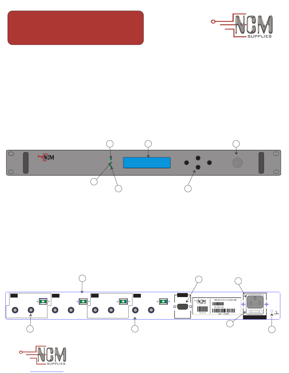
11- Visual alarm:
LCD backlight off and RF LED/LD LED fast blinking: NCM-OR-200 is turned off.
LCD backlight on, Power LED lights up green and RF LED/LD LED slow blinking:
NCM-OR-200 is starting up.
LCD backlight on and Power LED/RF LED/LD LED light up solid green: NCM-OR-200
is turned on and works correctly.
LCD backlight blinking and RF LED or LD LED light up solid red: NCM-OR-200 is
turned on and has alarm condition.
15- Audible alarm:
All alarm condition launch an audible alarm tone about 2000Hz,
with intervals of 500mS.
16- Critical Condition:
When the alarm conditions occurs and the system detects malfunction that may cause
damage to the PHOTODIODES, turn it off to protect the life of the PHOTODIODES.
(Warning: Contact NCM Optics for help).
17- Monitoring via RS-232 serial port:
Connect male DB9 from serial RS-232 cable into RS-232 connector on the rear panel.
Install and open the hyperterminal and configure: Bit rate: 9600bps, Data bits: 8, Parity:
None, Stop bits: 1
DANGER: CLASS- 3B LASER RADIATION- DO NOT STARE INTO
LASER BEAM
8125 NW 64th Street, Miami, Florida 33166
4 Channels Optical Receiver
NCM-OR-200
VENTILATION: Openings in the casing are provided for ventilation and
to ensure reliable operation of the product and to protect it from
overheating. Please, DO NOT block or cover these openings.
OR-200 should be installed in an environmentally controlled location