NCP 1000 Series User manual

Please ll in the following information and le it for
future reference.
MODEL NO.______________________________
SERIAL NO.______________________________
INSTALL DATE ___________________________
This unit should be installed in an
Outside Wall For
Thru-The-Wall
Installation Only!
All Units Department of Energy Listed
*Please consult the DOE Compliance Certification Database (https://tinyurl.com/NCPCondensers)
for a list of rated combinations of indoor and outdoor units.
NCP
Series:
1000
3000
4000
5000
Installation Guide
Thru the Wall
Condensing Unit
Read Installation Manual
Prior To Starting The Installation.
This manual must be left with the homeowner for future reference.
HEATING & A/C EQUIPMENT
NATIONAL
COMFORT
PRODUCTS
®
Thru-the-Wall Comfort for all types of Multi-Family Construction
National Comfort Products
A Division of National Refrigeration and Air Conditioning Products, Inc.
539 Dunksferry Road • Bensalem, PA 19020-5908
(800) 523-7138
www.nationalcomfortproducts.com
HEATING & A/C EQUIPMENT
NATIONAL
COMFORT
PRODUCTS
®
Go Thru-the-Wa

2

3
Installation Guide |Thru the Wall Condensing Units NCP Series 1000/3000/4000/5000
Page
Nomenclature................................................................................................................................................................ 4
Safety Warning ............................................................................................................................................................. 5
Before You Start............................................................................................................................................................ 6
High Voltage and Power Supply.................................................................................................................................... 7
Check for Clearances .................................................................................................................................................... 7
Unit Location Considerations........................................................................................................................................ 7
Refrigerant Piping Limits .............................................................................................................................................. 8
Leak Checking............................................................................................................................................................... 9
Evacuation, Electrical Connections................................................................................................................................ 10
Start Up, Sequence of Operations................................................................................................................................. 11
Refrigerant Charging..................................................................................................................................................... 12
Maintenance, Checkout Procedure................................................................................................................................ 14
Noise, Insulated Sound Cover....................................................................................................................................... 15
Important! Before Removing a Warranty Compressor.................................................................................................. 16
Wiring Diagrams........................................................................................................................................................... 17
Specifications, Dimensional Drawings .......................................................................................................................... 18-19
Matched systems with Cased Coils............................................................................................................................... 20
Matched systems with Air Handlers.............................................................................................................................. 20
Replacement Parts - NCP 1000 Series.......................................................................................................................... 21
Replacement Parts - NCP 3000 Series.......................................................................................................................... 22
Replacement Parts - NCP 4000 Series.......................................................................................................................... 23
Replacement Parts - NCP 5000 Series.......................................................................................................................... 24
Warranty ....................................................................................................................................................................... 25-26
IMPORTANT NOTE: DO NOT DESTROY OR THROW AWAY THIS MANUAL.
IT SHOULD BE KEPT IN A SAFE PLACE FOR FUTURE REFERENCE.

Installation Guide |Thru the Wall Condensing Units NCP Series 1000/3000/4000/5000
4
Split System Condensing Unit Nomenclature
NCP
NCP = Condensing Unit
4
Refrigerant
4 = R410A
18
Capacity
18 = 1.5 Ton
24 = 2 Ton
30 = 2.5 Ton
1000
Series
1000
3000
4000
5000
B A
Option
A = Standard
D = Deluxe
C = Crankcase Htr
L = Low Ambient
1
Factory Use
-
Generation

5
Installation Guide |Thru the Wall Condensing Units NCP Series 1000/3000/4000/5000
Safety Warnings!
This appliance is not intended for use by those (including children)
with reduced physical, sensory or mental capabilities, or lack of
experience and knowledge, unless they have been given supervision
or instructions concerning use of the appliance by a person
responsible for their safety. Children should be supervised to ensure
that they do not play with the appliance.
This appliance is intended to be installed up to 10,000 ft
(3,000 m) above sea level.
This appliance is only compatible with an Indoor unit that uses
R410A refrigerant.
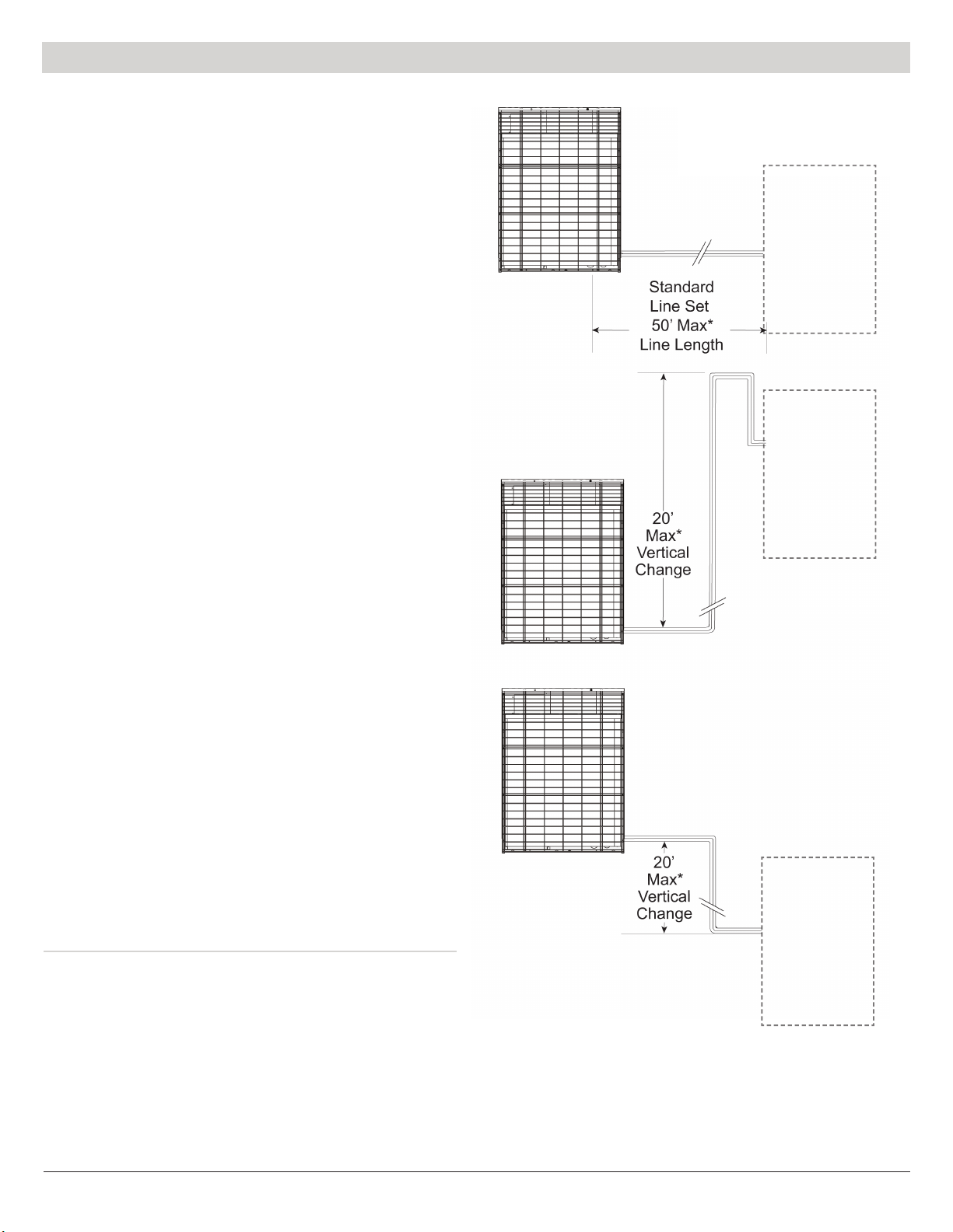
Wheninstalling thisunitwithan indoorevaporatingunit, themaximum
operating pressure is to be considered during the installation. The
maximum operating pressure of the system should not exceed the
value as indicated on the nameplate of this condensing unit.
This model series NCP4*******-** is a PARTIAL UNIT air-
conditioner, complying with PARTIAL UNIT requirements of
the International Standard of UL-60335-2-40, and must only be
connected to the other units that have been confirmed as complying
to corresponding PARTIAL UNIT requirements of the International
Standard of UL-60335-2-40.
This is a safety alert symbol. When you see this symbol on
labels or in manuals, be alert to the potential for personal injury.
Pay particular attention to words such as DANGER, WARNING or
CAUTION.
DANGER indicates an imminently hazardous situation, which will
result in serious injury or death
WARNING indicates a potentially hazardous situation, which could
potentially result in serious injury or death
CAUTION indicates a potentially hazardous situation, which may
result in minor or moderate injury. It is also used to alert against
practices that are unsafe and can result in property damage.
!WARNING
HIGH VOLTAGE! Disconnect ALL power before servicing.
Multiple power sources may be present. Failure to do so may
result in property damage, personal injury or death.
!WARNING
These instructions are intended as an aid to qualied, licensed
service personnel for proper installation, adjustment and operation of
this unit. Read these instructions thoroughly before attempting
installation or operation. Failure to follow these instructions may
result in improper installation, adjustment, service or maintenance
possibly resulting in re, electrical shock, property damage, personal
injury or death.
!WARNING
!WARNING
!WARNING
!CAUTION
!CAUTION
Installation and repair of this unit should be performed ONLY by
individuals meeting the requirements of an “entry level technician” as
specied by National Codes. Attempting to install or repair this unit
without such background may result in product damage, personal
injury or death.
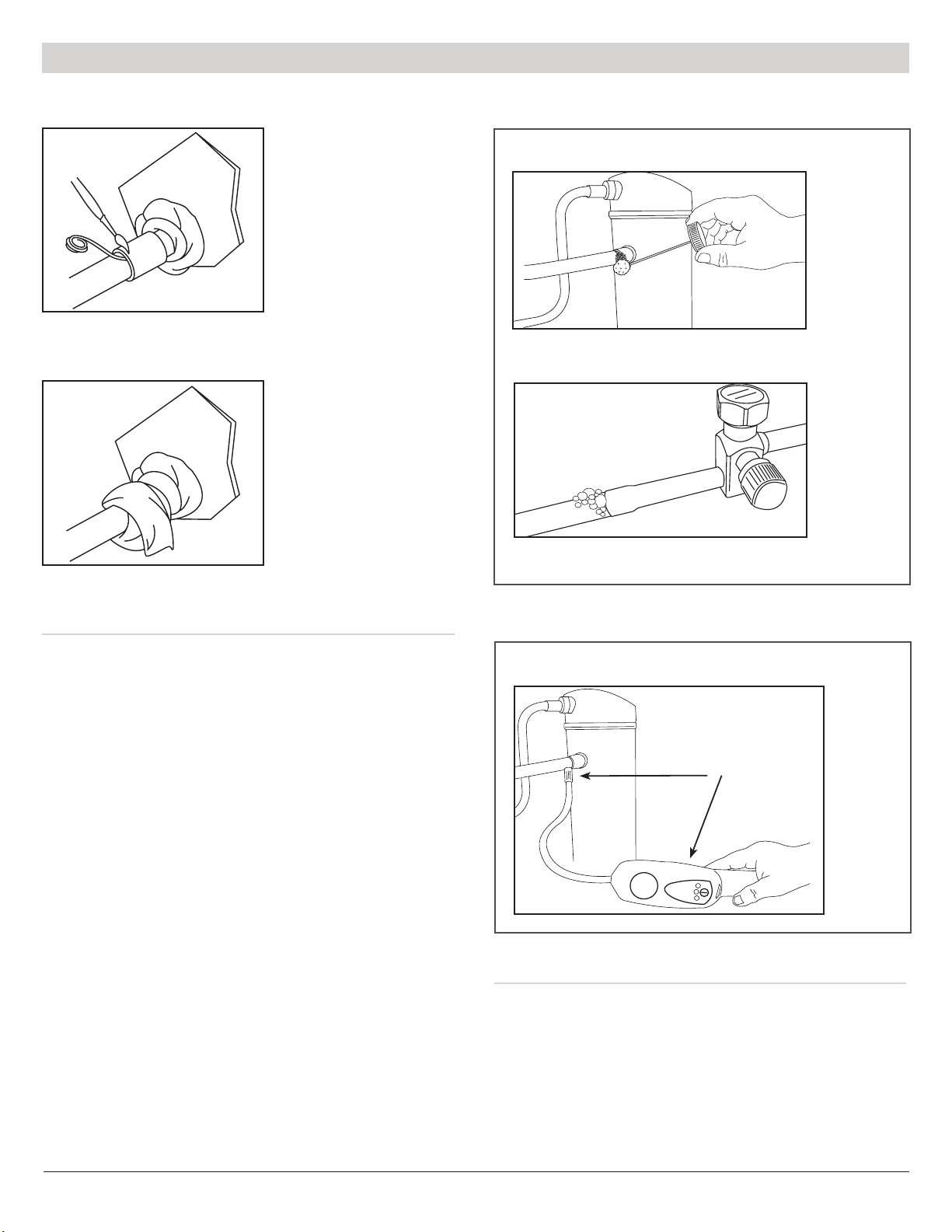
Do not use oxygen to purge lines or pressurize system for leak
test. Oxygen reacts violently with oil, which can cause an explosion
resulting in severe personal injury or death.
The unit must be permanently grounded. Failure to do so can cause
electrical shock resulting in severe personal injury or death.
Use care when handling scroll compressors. Some temperatures
could be hot!
Scroll compressors should NEVER be used to evacuate the air
conditioning system. Vacuums this low can cause internal electrical
arcing resulting in a damaged or failed compressor.
“USE COPPER SUPPLY WIRES ONLY”
!WARNING
Extreme caution should be exercised when opening the Liquid Line
Service Valve. Turn counter clockwise until the valve stem just
touches the rolled edge. No torque is required. Failure to follow this
warning will result in abrupt release of system charge and may result
in personal injury and /or property damage.

Installation Guide |Thru the Wall Condensing Units NCP Series 1000/3000/4000/5000
6
Installation Guide |Thru the Wall Condensing Units NCP Series 1000/3000/4000/5000
IMPORTANT — This Document is customer property and is to remain
with this unit. Please refer to service information pack upon completion
of work to register the unit’s warranty. These instructions do not cover all
variations in systems or provide for every possible contingency to be met
in connection with the installation. Should further information be desired
or should particular problems arise which are not covered sufficiently for
the purchaser’s purposes, the matter should be referred to your installing
dealer or local distributor before contacting the manufacturer.
The unit must never be placed on its side or upside down as
the compressor oil will run in the cooling circuit and seriously
damage the unit. Base pan must always be on the bottom of
the install.
Note: The manufacturer recommends installing only approved matched
split systems. Our split systems are A.H.R.I. and DOE rated only with
TXV indoor systems. (Please consult the DOE Compliance Certification
Database (https://tinyurl.com/NCPCondensers) for a list of rated
combinations of indoor and outdoor units. Combinations of outdoor
and indoor units that are not rated will require factory testing and listing
with DOE. Please consult the factory.) Some of the benefits of installing
approved matched split systems are maximum efficiency, optimum
performance and the best overall system reliability. Self-equalizing
components are required to reduce compressor starting problems. If
self-equalizing components are not used, field installed hard start kits
will be required. Hard start kits MUST be compatible with compressors.
Hard start kits MUST be compatible with Copeland compressors -
88-106/330 µF/Volts
Start relays to be sized to µF of capacitor used.
Before You Start
ALL phases of this installation must comply with NATIONAL, STATE
AND LOCAL CODES. The manufacturer assumes no responsibility for
equipment installed in violation of any code requirements.
Be sure that the electrical data specied on the unit rating plate
corresponds to what is available at the installation site and NEC for
installation requirements.
This unit MUST be installed in an outside wall for thru-the-wall installation
ONLY. No pad mounts.
Be sure that the electrical service provided to the building can handle the
load imposed by the unit.
Electrical - Low Voltage
Low Voltage Hook-up Diagram
Make all electrical connections in accordance with the National Electrical
Code and any pertinent local codes or ordinances. Use a separate branch
electrical circuit for this unit. Locate a disconnecting means within sight of
and readily accessible to the unit.
a. Line Voltage Connections
b. Connect the single phase power supply to unit contactor
terminal L1 and L2
c. Connect ground wire to lug
d. Low Voltage Connections
Consult the indoor unit installation instructions for thermostat connections.
Use a 2-wire thermostat cable between the units.
When locating the room thermostat, it should be in the natural circulating
path of room air. Avoid locations where the thermostat would be exposed to
cold air infiltration; drafts from windows, doors or other openings leading to
the outside; exposure to air currents from warm-or-cold air registers or to
exposure where the natural circulation of the air is cut off, such as behind
doors, above or below mantels, shelves, etc.
Low Voltage Maximum Wire Length:
Table defines the maximum total length of low voltage wiring from the
condensing unit to the indoor unit and to the thermostat.
24 VOLTS
WIRE SIZE MAX. WIRE LENGTH
18 AWG 150 ft.
16 AWG 225 ft.
14 AWG 300 ft.
Contactor
Field Wiring Low Voltage
White
Red
Blue

7
Installation Guide |Thru the Wall Condensing Units NCP Series 1000/3000/4000/5000
High Voltage Power Supply
Electrical - High Voltage
NOMINAL
VOLTAGE
MINIMUM
VOLTAGE
MAXIMUM
VOLTAGE
208-230 196 244
!WARNING
LIVE ELECTRICAL COMPONENTS!
During installation, testing, servicing and troubleshooting of this
product, it may be necessary to work with live electrical components.
Failure to follow all electrical safety precautions when exposed to live
electrical components could result in death or serious injury.
The high voltage power supply must agree with the equipment nameplate.
OR
Make certain that the volts, hertz, and phase correspond to that specified on
the unit rating plate, and that the service provided by the utility is sufficient
to handle the additional load imposed by this equipment.
Power wiring must comply with national, state, and local codes.
Follow instructions on unit wiring diagram located on the inside of the
access door, or cabinet and in the wiring diagrams included with the unit.
ON
OFF
Disconnect Switch
Thru-the-Wall
Condensing Unit
Install a separate disconnect
switch at the location of the
through the wall unit.
Ground the unit per national, state,
and local code requirements.
Minimum 48"
Vertical Clearance
Between Units
Minimum 12"
Horizontal Clearance
Between Units
Check for Clearances
Unit Location Considerations
WARNING: Warranty will be void on all units installed behind
brick facades (e.g. pigeon holes) or connected to ductwork
(See Note 1 below). All obstacles added to impede air ow
of the condensing unit will decrease performance, cause
premature equipment failure, and void all warranties. Consult
factory with any questions.
Note 1: No ducts are permitted to be connected to the intake or discharge
of the unit.
In thru-the-wall installation, due to the various types of wall construction,
it is not possible to provide detailed instructions. The following is a list of
general requirements and cautions for installing these units. The unit must
be installed level, both - top front to back and left to right.
1. Masonry walls must have a lintel to support the wall.
2. Extend the unit approximately 3/4"beyond outside surface of the wall.
Optional mounting angles can be purchased from the factory or field
fabricated for locating and mounting the unit in the wall.

Installation Guide |Thru the Wall Condensing Units NCP Series 1000/3000/4000/5000
8
Installation Guide |Thru the Wall Condensing Units NCP Series 1000/3000/4000/5000
3. The wall opening across the top and bottom must be flashed. Bottom
flashing to cover the full footprint of unit and extend up 2"on 3 sides. All
openings around the top, sides and bottom must be caulked and sealed.
Care must be taken not to plug the openings in the front of the base pan of
the unit. If the optional wall sleeve is used, caulk the spaces between the
sleeve and the wall. Completely ll the clearance between the unit and
the wall sleeve with a polyurethane foam sealant.
4. During periods of rain and wind the primary drainage path may not be
adequate to handle the load. Secondary precautions may also be required
but not limited to the following:
a. Seal flashing to unit
b. Floor drain
c. Additional field sealing of sheet metal joints
d. Sealing of unused access opening
5. Clearances to air inlets and outlets must be adequate to ensure no air flow
obstructions or recirculation of condenser air flow. Care must be taken to
locate the coil side of the unit away from loose debris that may clog airflow
inlet or outlet.
6. Some architectural designs of buildings will require the unit to be mounted
behind a decorative grille. The performance (capacity and efficiency) of
the unit may be reduced with the use of these decorative grilles. The less
resistive these grilles are to air flow, the better the units performance will be.
Outdoor louvers provided by others must be approved by NCP to maintain
unit performance and warranty.
7. If the unit is mounted behind a decorative grille, one or both of the
following items must be done to eliminate recirculation of air to the unit:
a. The front of the unit must be mounted tight to the inside of the
architectural grille
b. A barrier must be provided to prevent recirculation of air to the unit
(mixing of inlet and outlet air) when the front of the unit is mounted
back from the inside of the architectural grille
8. The unit must not be mounted in dead-end hallways or areas where there
is no fresh outside air circulation. Cool fresh outside air must be provided
for best unit operation. Thru-the-wall units may not be located where hot
exhausts from clothes dryer vents, kitchen vents, steam vents or corrosive
fumes could come in contact with coil side of unit.
9. 30"clearance is required for service accessibility on the inside service
panel.
10. A minimum 48"of vertical clearance and 12"of horizontal clearance
between units is required to minimize recirculation of condenser exhaust
air. For horizontal clearances less than 12", please consult National Comfort
Products.
11. Care must be taken when locating the unit. Locate away form bedrooms
as operational sounds may be objectionable. (See sound cover on page 15)
Refrigerant Piping
1. The maximum length of refrigerant lines from the through the wall unit
to indoor unit should NOT exceed fty (50) feet without contacting National
Comfort Products.
2. The maximum vertical change should not exceed twenty (20) feet without
contacting National Comfort Products.
Maximum Allowable Liquid Line Pressure Drop = 50 PSI
Subtract .43 PSI for each foot of Liquid Lift (if any)
Do Not Exceed this value when selecting Liquid Line
*Call National Comfort Products
for Greater Line Lengths
Air
Handler
or Coil
3. The unit has internally mounted service valves. Field tubing may be
routed through the locations provided in either the top or rear panels. Care
should be taken not to block access to internal components. Seal unused
knockouts with high grade sealant. Gaskets are provided for liquid and
suction lines.
Air
Handler
or Coil
Air
Handler
or Coil

9
Installation Guide |Thru the Wall Condensing Units NCP Series 1000/3000/4000/5000Installation Guide |Thru the Wall Condensing Units NCP Series 1000/3000/4000/5000
4. Run refrigerant lines as directly as possible. Field piping inside the
condensing unit should not block access to major components. Refrigerant
lines should not be in direct contact with the floor or ceiling joists. Use
insulated or suspension type hangers. When refrigerant lines run through
a wall, seal openings around the lines with a flexible material to avoid
vibration to the structure.
Note: Always use refrigeration grade copper tubing that is internally
clean and dry for refrigerant lines. Use clean hard drawn copper tubing
if no appreciable amount of bending is necessary. If soft copper is used,
avoid sharp bends which may cause a restriction. Always use heat
sink materials during brazing to prevent damage to service valves (See
page 10).
Note: Take precautions to prevent noise within the building structure due
to vibration transmission from the refrigerant lines For example:
When the refrigerant lines have to be fastened to floor joists or other
framing in a structure, use isolation type hangers.
Isolation hangers should also be used when refrigerant lines are run in
stud spaces or enclosed ceilings.
Where the refrigerant lines run through a wall or sill, they should be
insulated and isolated.
Isolate lines from all ductwork.
Minimize the number of 90� turns.
5. Standard refrigeration piping practices must be employed when installing
traps. When installing the condenser below the evaporator, the suction line
must be trapped with an inverted trap the height of the evaporator coil.
Consult the factory when total equivalent length of refrigerant lines exceeds
50 ft.
6. Insulate the vapor line with a minimum 1/2"foam rubber or other type
insulation having an adequate vapor barrier. For indoor units with a TXV,
a liquid line filter drier must be installed (SPORLAN #C-083-S or similar).
Liquid Line
Vapor Line
Insulation
IMPORTANT: The Vapor Line must always be insulated.
DO NOT allow the liquid line and vapor line to come in direct
(metal to metal) contact.
7. Install the refrigerant lines using the following procedure (See Steps 1
thru 4.)
a. Remove the service port caps and Schrader Cores of the liquid line
service valve and the vapor line service valve of the condensing unit.
Connect low pressure dry nitrogen to the liquid line valve service
port.
CAUTION: Dry nitrogen should always be supplied through
the tubing while it is being brazed, as the high temperature
required for brazing will cause oxidation of the copper unless
an inert atmosphere is provided. The ow of dry nitrogen
should continue until the joints have cooled. Always use a
pressure regulator and safety valve to ensure that only low
pressure nitrogen is introduced into the tubing. Only a small
ow is necessary to displace air and prevent oxidation.
b. Provide a heat sink at the service valve such as wrapping a wet rag
around it, to prevent damage during the brazing operation
c. Braze the liquid line to the service valve. Allow the nitrogen to keep
flowing when brazing the refrigerant line until all brazed joints are
completed.
d. Provide a heat sink to the vapor line service valve of the condensing
unit
e. Braze the vapor line to the service valve
f. When tubing installation is complete, seal openings around tubing
where tubing enters the unit cabinet.
Step 1:
The tubing should be cut
square. Make sure it is
round and free of burrs
at the connecting ends.
Clean the tubing to prevent
contaminants from entering
the system.
Step 2:
Wrap a wet rag around the
copper stub of the service
valve before brazing.

Installation Guide |Thru the Wall Condensing Units NCP Series 1000/3000/4000/5000
10
Step 3:
Flux the copper tube and
insert into the stub. Braze the
joint. No ux is necessary if a
low to zero-silver braze alloy
is used.
Step 4:
After brazing, quench with a
wet rag to cool the joint and
remove any ux residue.
Leak Checking
Leak checking of refrigerant line braze joints and evaporator unit using
dry nitrogen. (See Step 5a)
1. Replace service port cap of the vapor line service valve (cap was removed
for brazing operations).
2. Connect dry nitrogen source to the service port of the liquid line service
valve. Pressurize refrigerant lines and indoor coil to approximately 100 psig.
3. Check for leaks using a liquid soap solution. If any leaks are detected,
purge the nitrogen, repair the leak(s) and repeat the leak check procedure.
Leak checking of refrigerant line braze joints and evaporator unit using
R410a refrigerant. (See Step 5b)
1. Connect R410a source to the service port of the liquid line service valve.
Use of a manifold gauge set will facilitate connecting and disconnecting of
the refrigerant source for leak checking. Pressurize refrigerant lines and
indoor coil with refrigerant gas.
2. Leak check with an electronic leak detector or liquid soap solution. If
any leaks are detected, use a refrigerant recovery system to remove the
refrigerant. Repair the leak(s) and repeat the leak check procedure.
Step 5a:
Step 5b:
Apply liquid soap solution to check for leaks
Bubbles forming in the liquid soap solution indicates a leak
Using a liquid soap solution
Using an electronic leak detector
Leak check with an
electronic leak detector
1. Connect the vacuum pump to the service ports of the liquid line and vapor
line service valves. If the vacuum pump lines do not contain shut-off valves,
hook up the vacuum pump through a manifold gauge set, as the vacuum
pump lines must be closed for step 4 below.
a. If the evacuation is being performed on a new system installation, the
condensing unit service valves should be kept in the closed position.
The vacuum pump will then be able to evacuate the refrigerant lines
and evaporator coil.
Evacuation

11
Installation Guide |Thru the Wall Condensing Units NCP Series 1000/3000/4000/5000
Note: Check for leaks if unable to get to 300 microns.
3. Allow the pump to continue running an additional 15 minutes. Turn off
the pump and leave connections secured. After 10 minutes if system fails
to hold 500 microns or less, check all connections for tight fit and repeat
evacuation procedure.
4. Isolate the vacuum pump by closing the shut-off valves on vacuum pump
lines or test gauge manifold.
5. Open the service valves. Opening the service valves will allow the refrigerant
in the condensing unit to enter the refrigerant lines and evaporator coil. The
vacuum pump can now be disconnected. (See Step 6 and 7)
Electrical Connections
Note: Make certain that the volts, hertz, and phase correspond to that
specified on the unit rating plate, and that the service provided by the
utility is sufficient to handle the additional load imposed by this equipment.
Step 6:
This is not a back seating
valve. To open the valve
remove the valve cap with
an adjustable wrench. Insert
a 3/16" or 5/16" hex wrench
into the stem. Back out
counter-clockwise until the
valve stem just touches the
retaining ring. CAUTION
(Certain combination hex
wrenches designed for
service valves may not
properly seat into the valve
stem and may lead to
stripping. Make sure the hex
wrench is seated completely
in the valve when rst
opening)
Step 7:
Replace the valve cap
nger tight then tighten an
additional 1/12 turn or 1/2
hex at. A metal-to-metal
seal is now complete.
Complete normal factory
recommended procedures.
b. If the evacuation is being performed on an installation where the
condensing unit factory charge has been lost, the service valves
should be opened.
2. Following the vacuum pump manufacturer’s instructions, allow the pump
to operate until the system has been evacuated down to 300 microns.
Start Up
1. Ensure that directions on page 6 through 10 have been completed. Check
numbers once done.
2. Turn on disconnect(s) to apply power to all equipment.
3. Wait one (1) hour before starting the unit if compressor crankcase heater
accessory is used and the Outdoor Ambient is below 70º
4. Set system thermostat to ON.
Stabilize the system by operating for a minimum of 20 minutes. At startup,
or whenever charge is removed or added, the system must be operated for
a minimum of 20 minutes to stabilize before accurate measurements can
be made.
Sequence of Operations
On a “call for cooling”, the thermostat completes circuits R-Y and R-G.
Circuit R-Y energizes the contactor starting the condenser fan motor and
compressor circuit. R-G energizes the indoor unit blower relay starting the
indoor blower motor.
When the thermostat is satisfied, its contacts open, de-energizing the contactor
and blower relay. Compressor and motors should stop.

Installation Guide |Thru the Wall Condensing Units NCP Series 1000/3000/4000/5000
12
System Charge Adjustment
Temperature Measurements
Check that the outdoor temperature is 65°F or higher before adjusting
charge based on subcooling. Subcooling (in cooling mode) is the only
recommended method of charging the system. For reference, use the charge
chart above and refer to page 20 for your systems proper subcooling value.
For best results the indoor temperature should be kept between 70º F to
80º F.
Installers Notes:
• Condenser door must be in place while adjusting subcooling
• Ambient temperature must be between 65°F-95°F
• Indoor return air temperature must be above 70°F
• Allow 20 minutes of run time at premium conditions before adjusting
charge
• Driving rain against the condenser coil can affect setting proper subcooling
• Add charge to increase subcooling
• Remove charge to decrease subcooling
• Indoor units must be equipped with a thermal expansion valve (TXV)
NATIONAL COMFORT PRODUCTS R-410A CHARGING CHART
LIQUID PRESSURE AT
SERVICE VALVE (psig)
°F °F °F °F °F °F °F °F °F °F °F
12 13 14 15 16 17 18 19 20 21 22
R-410A REQUIRED LIQUID LINE TEMPERATURE (°F)
251 72 71 70 69 68 67 66 65 64 63 62
259 74 73 72 71 70 69 68 67 66 65 64
266 76 75 74 73 72 71 70 69 68 67 66
274 78 77 76 75 74 73 72 71 70 69 68
283 80 79 78 77 76 75 74 73 72 71 70
291 82 81 80 79 78 77 76 75 74 73 72
299 84 83 82 81 80 79 78 77 76 75 74
308 86 85 84 83 82 81 80 79 78 77 76
317 88 87 86 85 84 83 82 81 80 79 78
326 90 89 88 87 86 85 84 83 82 81 80
335 92 91 90 89 88 87 86 85 84 83 82
345 94 93 92 91 90 89 88 87 86 85 84
364 98 97 96 95 94 93 92 91 90 89 88
374 100 99 98 97 96 95 94 93 92 91 90
384 102 101 100 99 98 97 96 95 94 93 92
395 104 103 102 101 100 99 98 97 96 95 94
406 106 105 104 103 102 101 100 99 98 97 96
416 108 107 106 105 104 103 102 101 100 99 98
427 110 109 108 107 106 105 104 103 102 101 100
439 112 111 110 109 108 107 106 105 104 103 102
450 114 113 112 111 110 109 108 107 106 105 104
462 116 115 114 113 112 111 110 109 108 107 106
474 118 117 116 115 114 113 112 111 110 109 108
Note: For longer linesets, the charge MUST be adjusted to meet the
required subcool and superheat values as instructed on page 20 for
cooling operation. Use actual linear length with the table below.
Refrigerant Charging
The condensing units are tested in factory based on 10 ft of refrigerant lines.
If the actual line length is greater or less than 10ft, add or remove refrigerant
at the rate of 0.6 ounces per foot.
When replacing an R-22 system, it is recommended that new line sets
be used. If the old line sets are to be used, they MUST be flushed with
a commercial flushing agent. R410A refrigerant oil is not compatible with
mineral oil.
IMPORTANT: The outdoor unit comes with refrigerant,
which may not be enough for your system. When installing
a condensing unit with a matched Indoor coil or air-handler,
system charge and TXV setting MUST be adjusted to meet
the required subcool and superheat values as instructed on
page 20. All other indoor units will require factory testing and
certication with DOE. Be sure both service valves are closed
during tubing installation and leak checked to avoid loss of
charge. A liquid line lter drier must be installed (SPORLAN
#083-S or similar).
If the condensing unit charge was lost for any reason, add factory refrigerant
charge listed on condensing unit data plate plus adjustments describe above
to meet the required subcool as instructed on page 20. If the unit is operating
during charge adjustment, the access panel must be in place to prevent high
head pressure which would shut down the unit.

13
Installation Guide |Thru the Wall Condensing Units NCP Series 1000/3000/4000/5000
Note: All information based on the following Air Flow Chart. Required
superheat varies for each system. Refer to page 20 for recommended
superheat. Superheat temperature measurements should be taken within
3 feet of the compressor suction line connection.
Note: Oil charge is polyester 32bce.
Ounces & Pounds of R410A Required for Line Sets
Weight Tubing Size 10' 15' 20' 25' 30' 35' 40' 45' 50'
Ounces 3/8" - 3/4" 0 3.5 7 10.5 14 17.5 21 24.5 28
Pounds 3/8" - 3/4" 0 0.21875 0.4375 0.65625 0.875 1.09375 1.3125 1.53125 1.75
!CAUTION
1. Connect the charging cylinder to the manifold gauge set. Open the
charging cylinder valve and bleed air out of the charging hose at the manifold
gauge set connection.
2. Tighten the manifold gauge set charging connection. Open the main
manifold gauge set valve and introduce refrigerant into the liquid side of
the system.
3. When the correct refrigerant charge level is obtained, remove the manifold
gauge set.
4. Replace the gauge port caps.
Permanently stamp the unit data plate with the total amount of refrigerant
in the system.
Airow Chart For Coil Matches
Outdoor Model Indoor Model Airow
(SCFM)1
NCP4181000B-** NCC418AA-* 620
NCP4183000B-** NCC418AA-* 620
NCP4184000B-** NCC418AA-* 620
NCP4185000B-** NCC418AA-* 620
NCP4241000B-** NCC424AA-* 820
NCP4243000B-** NCC424AA-* 820
NCP4244000B-** NCC424AA-* 820
NCP4245000B-** NCC424AA-* 820
NCP4301000B-** NCC430AA-* 890
NCP4303000B-** NCC430AA-* 890
NCP4305000B-** NCC430AA-* 920
Low Suction Pressure Operation!
Compressor Damage!
Do not operate with a restricted suction. Do not operate with the
lowpressure cut-out bridged. Do not operate compressor without
enough system charge to maintain at least 0.5 bar (7.25 psi) suction
pressure. Allowing pressure to drop below 0.5 bar (7.25 psi) for
more than a few seconds may overheat scrolls and cause early
drive bearing damage.
The system should be liquid-charged through the liquid-receiver
shut-off valve or through a valve in the liquid line. The use of a filter
drier in the charging line is highly recommended. Because R410A and
R407C are blends and scrolls have discharge check valves, systems
should be liquid-charged on both high and low sides simultaneously
to ensure a positive refrigerant pressure is present in the compressor
before it runs. The majority of the charge should be placed in the high
side of the system to prevent bearing washout during first-time start
on the assembly line.
1. The airflow is conducted at wet coil conditions. The airflow in the table above is
recommended to get best performance out of your system
https://www.msn.com/en-us/
feed
CAUTION: It is very important that when charging a system to
charge liquid refrigerant into the high side only. It is not good
practice to ood liquid refrigerant from a refrigerant cylinder
into the crankcase of the a stationary compressor through the
suction line. If additional charge is required carefully charge
liquid incrementally into the low side of the system with the
compressor operating. Excessive liquid introduced into the
suction line will damage the compressor.
Air Flow Chart for Air Handler Matches
Outdoor Model Indoor Model
Motor
Speed
Color
(Tap)
Static
(in. wc.)
Airow
(SCFM)1
NCP4181000B-** NAH424 MFA-** Black (2) 0.3 600
NCP4183000B-** NAH424 MFA-** Black (2) 0.3 600
NCP4184000B-** NAH424 MFA-** Black (2) 0.3 600
NCP4185000B-** NAH424 MFA-** Black (2) 0.3 600
NCP4241000B-** NAH430 MFA-** Blue (3) 0.3 790
NCP4243000B-** NAH430 MFA-*** Blue (3) 0.3 790
NCP4244000B-** NAH430 MFA-** Blue (3) 0.3 790
NCP4245000B-** NAH430 MFA-** Blue (3) 0.3 790
NCP4301000B-** NAH430 MFA-** Red (5) 0.3 920
NCP4303000B-** NAH430 MFA-** Red (5) 0.3 920
NCP4305000B-** NAH430 MFA-** Red (5) 0.3 920
1. The airflow is conducted with a filter at wet coil conditions. The airflow in the table
above is recommended to get best performance out of your system

Installation Guide |Thru the Wall Condensing Units NCP Series 1000/3000/4000/5000
14
Maintenance
1. Annually clean the inside of the unit to keep the weep holes in the base pan
open to assure proper drainage of water from the unit.
2. Keep the condenser coil clean and free of anything that restricts free
air flow. For sea coast applications the condenser coil should be washed
periodically to remove salt accumulation.
3. Reduced indoor air flow through a duct system will cause the indoor coil
to ice up in cooling. If this condition is not corrected, premature system
failure will result. Indoor air filters should be cleaned and changed regularly.
4. Annually check units mounting to structure to ensure integrity. Seal
between cabinet and/or sleeve for air or water leakage. Check exposed
surfaces for corrosion. Replace or paint parts as required. This maintenance
is critical to prevent stains and damage to exterior surface of building.
5. Inspect refrigerant piping for leaks and suction line insulation for
deterioration and damage. Improper insulation can cause condensate water
damage.
6. Pressure and temperature readings of the high and low sides of the
system should be checked for proper superheat and/or subcooling. Correct
if required. See System Charge Adjustment on page 12.
7. Check motor amperage to nameplate value, inspect the motor mounting
and prop fan hub for tightness and rust or corrosion. Observe the prop fan
blade for balance.
8. Inspect the wire connections and contactor dry contacts for evidence of
arcing, over heating, or deterioration.
Checkout Procedures and Troubleshooting
Checkout Procedures
After installation has been completed, it is recommended that
the system be checked against the following list:
1. Leak check refrigerant lines.
2. Properly insulate suction lines and ttings.
3. Properly secure and isolate all refrigerant
lines.
4. Seal passages through masonry. If mortar is
used, prevent mortar from coming into direct
contact with copper tubing.
5. Verify that all electrical connections are tight.
6. Observe outdoor fan during on cycle for
clearance and smooth operation.
7. Be sure the indoor condensate line drains
freely. Pour water into drain pan.
8. Be sure that supply registers and return
grilles are open and unobstructed.
9. Be sure that a return air lter is installed.
10. Be sure that the correct indoor airow setting
is used.
Service Access
Note: 30"of clearance is required for service accessibility on the
inside. All units are serviceable from the inside.

15
Installation Guide |Thru the Wall Condensing Units NCP Series 1000/3000/4000/5000
Noise
We design our unit as quiet as possible; please keep in mind when locating
the unit that it does make noise. Use common precautions as you would for
other mechanical appliances pertaining to noise.
Outdoor Sound: 79.8 dBA (AHRI Standard 270-2008)
Sound Cover
As an option, we offer an Insulated Sound Cover for installation over the
inside cover of the unit.
Indoor Sound
Without Insulated Sound Cover: 70.4 dBA
With Insulated Sound Cover: 68.3 dBA
(AHRI Standard 350-2008)
The Insulated Sound Cover will be supplied with insulated handles installed
and assembled.
To install onto the unit, either the top or bottom will need to be removed
depending on the exit point of the tubing. (3 screws)
Refrigerant Line
Access Wall Sleeve
Insulated
Sound Cover
Access provided to
Line Set Connections,
Line Voltage, Low Voltage
and Refrigerant Line
Access
Sound Covers Available
1000 I.D. Cover
3000 I.D. Cover
4000 I.D. Cover
5000 I.D. Cover

Installation Guide |Thru the Wall Condensing Units NCP Series 1000/3000/4000/5000
16
IMPORTANT!!!
BEFORE REMOVING A WARRANTY COMPRESSOR,
PLEASE FILL OUT THE FOLLOWING
AND CALL (800) 523-7138.
REMOVAL OF COMPRESSOR WITHOUT FACTORY VERIFICATION
CAN LEAD TO WARRANTY CREDIT BEING DENIED
1. Incoming Voltage to Compressor at Contactor is:__________Volts
2. Compressor Starting AMP Draw:__________ A
3. Compressor Winding OHM Reading between Terminals C & S:__________
4. Compressor Winding OHM Reading between Terminals C & R:__________
5. Compressor Winding OHM Reading between Terminals R & S:__________
6. Compressor Winding OHM Reading between Terminals C & Ground:__________
7. Compressor Winding OHM Reading between Terminals R & Ground:__________
8. Compressor Winding OHM Reading between Terminals S & Ground:__________
9. Run Capacitor Reading from HERM to COM:__________
10. Start Capacitor Reading if Used:__________
11. If the Compressor is Operating Please Indicate the Following:
Suction Pressure:__________psig Discharge Pressure___________psig
Super Heat:_____________F Subcooling:______________F
AC
Ω
Ω
Ω
Ω
Ω
Ω
HERM
FAN
TOP VIEW OF CAPACITOR
C
uF
+
uF
+

17
Installation Guide |Thru the Wall Condensing Units NCP Series 1000/3000/4000/5000
LEGEND
CAP - DUAL CAPACITOR
CC - COMPRESSOR CONTACTOR
CCH - CRANKCASE HEATER (OPTIONAL)
COMP - COMPRESSOR
CFM - CONDENSER FAN MOTOR
HPS - HIGH PRESSURE SWITCH
LPS - LOW PRESSURE SWITCH
NCP SERIES
8/18/2023 rev 1
JOB NUMBER
DATEDRAWN BY
BS
WIRING DIAGRAM
14299226
1000, 3000, 4000 & 5000
FAX: 215-639-1674
Phone: 800-523-7138
Bensalem, Pa. 19020
539 DUNKSFERRY RD.
CFM
L1L2
DISCONNECT
NON-FUSED
OPTIONAL
FUSED OR
GCY R
CC
C
H
F
CAP
LPS HPS
C
SR
COMP
208-230 VAC NOMINAL VOLTAGE
196 VAC MINIMUM VOLTAGE
244 VAC MAXIMUM VOLTAGE
YELLOW
BLACK
RED
BLACK
WHITE
YELLOW
BROWN
BLUE
REDWHITE
RED
BLUE
BLACK
BLACK
CCH
(OPTIONAL)
1
2
NOTE:
1. Crankcase heater is available as a factory installed option.
2. Certain units utilize CFM's that do not require a capacitor. This BROWN wire will not be
included and a single capacitor will be used for the COMP.

Installation Guide |Thru the Wall Condensing Units NCP Series 1000/3000/4000/5000
18
1000 Series w/ matches up to 12.5 SEER2*
All Units 208/230-1-60Hz
Model Shipping
weight (lbs)
Compressor MCA MOP
RLA LRA
NCP4181000B-** 160 10.3 45.7 14.2 20
NCP4241000B-** 165 11.7 59.5 15.9 25
NCP4301000B-*1 170 12.8 65 17.8 30
NCP4301000B-*2 170 10.8 65 15.3 25
Cond. Fan Motor 418/424 1/4 HP, 1600 RPM, 1.3 FLA
430 1/5 HP, 1650 RPM, 1.8 FLA
Condenser Coil 3.61 ft2 Face Area, 16 FPI
Dimensions 26 1/4" W x 28 5/8" H x 18 1/2" D
Liquid Valve 3/8" Suction Valve 3/4"
*When matched with NAH4**MF Air Handler
3000 Series w/matches up to 13 SEER2*
All Units 208/230-1-60Hz
Model
Shipping
Weight
(lbs)
Compressor
MCA MOP
RLA LRA
NCP4183000B-** 160 10.3 45.7 14.2 20
NCP4243000B-** 165 11.7 59.5 15.9 25
NCP4303000B-*1 170 12.8 65 17.8 30
NCP4303000B-*2 170 10.8 65 15.3 25
Cond. Fan Motor 418/424 1/4 HP, 1600 RPM, 1.3 FLA
430 1/5 HP, 1650 RPM, 1.8 FLA
Condenser Coil 3.77 ft2 Face Area, 16 FPI
Dimensions 24 1/8" W x 32" H x 18 1/2" D
Liquid Valve 3/8" Suction Valve 3/4"
22 1
4
"
43
8
"
26 1
4
"
28 7
8
"
57
8
"
10 1
8
"
16 3
8
"
17
8
"
37
8
"
63
4
"
93
8
"
61
8
"
10 7
8
"
13 1
2
"
18 3
4
"
28 7
8
"
28 7
8
"
18 1
2
"
26 1
8
"
25 3
4
"
51
4
"
24 1
4
"
32 1
4
"
51
4
"
95
8
"
14 5
8
"
35
8
"
15
8
"
91
4
"
81
4
"
73
8
"
12 "
12 1
8
"
1
8
18 3
4
"
32 1
4
"
18 1
2
"
32 1
4
"
24 1
8
"
Note: Some dimensions that are shown in these drawings are
measured between the edges of screw heads.

19
Installation Guide |Thru the Wall Condensing Units NCP Series 1000/3000/4000/5000
*When matched with NAH4**MF Air Handler
4000 Series w/matches up to 12.5 SEER2*
All Units 208/230-1-60Hz
Model
Shipping
Weight
(lbs)
Compressor
MCA MOP
RLA LRA
NCP4184000B-** 160 10.3 45.7 14.7 20
NCP4244000B-** 170 11.7 59.5 16.4 25
Cond. Fan Motor 1/5 HP, 1650 RPM, 1.8 FLA
Condenser Coil 3.14 ft2 Face Area, 16 FPI
Dimensions 30" W x 23" H x 22 1/2" D
Liquid Valve 3/8" Suction Valve 3/4"
5000 Series w/ matches up to 14 SEER2*
All Units 208/230-1-60Hz
Model Shipping
weight (lbs)
Compressor MCA MOP
RLA LRA
NCP4185000B-** 170 10.3 45.7 14.7 20
NCP4245000B-** 185 11.5 59.5 16.2 25
NCP4305000B-** 190 14.1 67.9 19.4 30
Cond. Fan Motor 1/5 HP, 1650 RPM, 1.8 FLA
Condenser Coil 418 4.59 ft2 Face Area, 16 FPI
424/430 4.59 ft2 Face Area, 14 FPI
Dimensions 26 7/8” W x 38 7/8” H x 18 1/2” D
Liquid Valve 3/8" Suction Valve 3/4"
37
8
"
16 3
4
"
30"
23 1
4
"
11 1
8
"
17 1
8
"
21
4
"
41
4
"
63
4
"
11
2
"
3
1
2
"
15
8
"
65
8
"
11 1
4
"
23
8
"
23 1
4
"
22 7
8
"
29 7
8
"
22 1
2
"
23 1
4
"
75
8
"
27 5
8
"
27 1
4
"
39 1
8
"
53
4
"
10 7
8
"
16 3
8
"
13
8
"
31
4
"
10 1
2
"
11
2
"
10 3
4
"
15 1
2
"
11
4
"
33
8
"
10 5
8
"
39 1
8
"
18 3
4
"
18 1
2
"
39 1
8
"
27 1
8
"
Note: Some dimensions that are shown in these drawings are
measured between the edges of screw heads.

Installation Guide |Thru the Wall Condensing Units NCP Series 1000/3000/4000/5000
20
Matched system with Cased Coil
Outdoor Model Indoor Model Rated Capacity
(Btu/h) Rated EER21
Nominal
Airow2
(SCFM)
SEER23Liquid Subcool4
(°F)
Suction Superheat5
(°F)
NCP4181000B-** NCC418AA-* 18,000 10.2 620 11.7 15-19 9-13
NCP4241000B-** NCC424AA-* 22,600 10.5 820 11.7 12-16 13-17
NCP4301000B-** NCC430AA-* 26,400 10.2 890 11.7 15-19 12-16
NCP4183000B-** NCC418AA-* 18,000 10.2 620 11.7 15-19 12-16
NCP4243000B-** NCC424AA-* 22,600 10.5 820 11.7 12-16 12-16
NCP4303000B-** NCC430AA-* 26,800 10.2 890 11.7 14-18 11-15
NCP4184000B-** NCC418AA-* 18,000 10.5 620 11.7 16-20 12-16
NCP4244000B-** NCC424AA-* 22,600 10.5 820 11.7 14-18 13-17
NCP4185000B-** NCC418AA-* 18,500 11 620 12 12-16 12-16
NCP4245000B-** NCC424AA-* 24,000 11 820 12 12-16 13-17
NCP4305000B-** NCC430AA-* 28,000 10.5 920 12 13-17 12-16
Matched system with Air Handler
Outdoor Model Indoor Model Indoor Motor
Speed
Rated
Capacity
(Btu/h)
Rated
EER21
Nominal
Airow2
(SCFM)
SEER23Liquid Subcool4
(°F)
Suction
Superheat5
(°F)
NCP4181000B-** NAH424MFA-** Black (2) 18,000 11 600 12.5 15-19 7-11
NCP4241000B-** NAH430MFA-** Blue (3) 22,600 11 790 12.5 13-17 11-15
NCP4301000B-** NAH430MFA-** Red (5) 27,000 11 920 12 15-19 13-17
NCP4183000B-** NAH424MFA-** Black (2) 18,000 11 600 13 14-18 7-11
NCP4243000B-** NAH430MFA-** Blue (3) 23,000 11 790 13 14-18 12-16
NCP4303000B-** NAH430MFA-** Red (5) 27,000 11 920 12 15-19 13-17
NCP4184000B-** NAH424MFA-** Black (2) 18,000 11 600 12.5 16-20 8-12
NCP4244000B-** NAH430MFA-** Blue (3) 23,000 11 790 12.5 14-18 12-16
NCP4185000B-** NAH424MFA-** Black (2) 18,000 12 600 14 11-15 14-18
NCP4245000B-** NAH430MFA-** Blue (3) 24,000 12 790 14 12-16 12-16
NCP4305000B-** NAH430MFA-** Red (5) 28,400 11.5 920 13.5 15-19 12-16
1. EER2 is determined based on the Evaporator match listed in this table
2. Airow values are determined at wet coil conditions
3. SEER2 is determined base on the Evaporator match listed in this table
4. Subcooling must be measured at condenser liquid valve
5. Superheat must be measured at evaporator outlet at suction line
This manual suits for next models
3
Table of contents
Other NCP Heat Pump manuals
Popular Heat Pump manuals by other brands

Dimplex
Dimplex SIKH 9 ME Installation and operating instructions

American Standard
American Standard YC 102-301 Series Installation operation & maintenance

Henden
Henden HHP14 Installation & owner's manual

Genvex
Genvex PREMIUM PREHEAT 250 installation manual

Daikin
Daikin Super Multi NX FTXG25JV1BW Service manual

Carrier
Carrier 25HPA6 installation instructions

Alpha
Alpha E-Tec EHP Design, installation and servicing instructions

Enertech
Enertech CTC EcoLogic Family series Installation and Maintenance

Nibe
Nibe F750 Installer manual

Dimplex
Dimplex WI 10TU Installation and operating instructions

Rotex
Rotex HPU ground installation manual

York
York YZH024 THRU 060 Technical guide