manuals.online logo
Brands
  1. Home
  2. •
  3. Brands
  4. •
  5. NCR
  6. •
  7. Camera Accessories
  8. •
  9. NCR 7360-K074 Manual

NCR 7360-K074 Manual

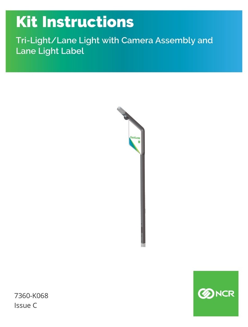
Kit Instructions
IPCamera (Standard) Field Upgrade
7360-K074
Issue A
ii
The product described in this document is a licensed product of NCR Corporation.
NCR is a registered trademark of NCR Corporation. NCR FastLane SelfServ™ Checkout is a trademark of NCR Corporation in the
United States and/or other countries. Other product names mentioned in this publication may be trademarks or registered
trademarks of their respective companies and are hereby acknowledged.
The terms HDMI and HDMI High-Definition Multimedia Interface, and the HDMI Logo are trademarks or registered trademarks of
HDMI Licensing LLC in the United States and other countries.
Where creation of derivative works, modifications or copies of this NCR copyrighted documentation is permitted under the terms
and conditions of an agreement you have with NCR, NCR's copyright notice must be included.
It is the policy of NCR Corporation (NCR) to improve products as new technology, components, software, and firmware become
available. NCR, therefore, reserves the right to change specifications without prior notice.
All features, functions, and operations described herein may not be marketed by NCR in all parts of the world. In some instances,
photographs are of equipment prototypes. Software screen images are representative, and in some cases, may not match a
customer’s installed software exactly. Therefore, before using this document, consult with your NCR representative or NCR office
for information that is applicable and current.
Copyright © 2022
By NCR Corporation
864 Spring St. NW
Atlanta, GA 30308
United States
All Rights Reserved
iii
Revision Record
Issue Date Remarks
AAug 2022 First Issue
IP Camera Field Upgrade (Standard)
This publication provides procedures for installing the IP Camera Field Upgrade
(Standard) to the NCRFastLane SelfServ™ Checkout (7360).
Kit Contents
Part Number Description
497-0532762 Kit - IP Camera Field Upgrade (Standard)
497-0532090 Tri-Light Cable Channel Bracket
497-0532089 Tri-Light C-clamp Bracket
006-8611462 Screw - M4x8 Phillips Panhead Machine
497-0532122 Tri-LightCamera Bracket - VTC
497-0532349 IP Camera - PoE/12V, VTC WDIN28ATM1P, 2MP, 2.8mm Lens
009-0007953 Nut M3 Self Locking
2 IP Camera Field Upgrade (Standard)
Part Number Description
006-8624498 Screw - M4x.7x8mm, Flat Head, Stainless
* 007-9714414 Tie Strap Plain 5.60LG
* 497-0519622 Label - Hole Cover, Mid - Silver (3 pcs)
* 497-0423108 Instructions Kit (Reference Sheet)
* Items marked with an asterisk are not called out on the image.
Customer Supplied Devices
The following devices must be supplied by the customer:
• 802.3at (PoE+) Compatible Switch/Injector
• Ethernet (LAN) Cable
IP Camera Field Upgrade (Standard) 3
Installation Procedure
To install the IPCamera Field Upgrade (Standard), follow these steps:
Note: Ensure that the NCR Customer Helpdesk is informed when the Tri-Light/Lane
Light with IPCamera is installed in the store.
1. Remove the existing Tri-Light/Lane Light Assembly, if necessary. For more
information, refer to Removing the Tri-Light/Lane Light (R6) on the next page.
2. Install the IP Camera (Standard) to the Tri-Light/Lane Light Assembly, refer to
Installing the IP Camera on page6.
3. Install the Tri-Light with IPCamera Assembly. For more information, refer to
Installing the Tri-Light/Lane Light with IPCamera Assembly on page10.
4. Configure the Camera Settings. For more information, refer to Configuring the Camera
Settings on page49.
Note: For more information about setting up the camera, refer to VTCNetwork
Camera User Manual.
4 IP Camera Field Upgrade (Standard)
Removing the Tri-Light/Lane Light (R6)
To remove the Tri-Light/Lane Light Assembly, follow these steps:
1. Turn off the NCRSelfServ Checkout software and hardware systems. For more
information, refer to the NCR SelfServ™ Checkout (7360) Hardware Service Guide
(B005–0000–2378).
2. Remove one (1) screw to detach the Tri-Light/Lane Light Assembly from the Tri-
Light/Lane Light Pole, as shown in the image below.
IP Camera Field Upgrade (Standard) 5
3. Lift the Tri-Light/Lane Light Assembly and then disconnect the cables.
Tip: Mark all cables as to where they are connected to quickly determine the
corresponding port when reconnecting the cables.
6 IP Camera Field Upgrade (Standard)
Installing the IP Camera
To install the IPCamera (Standard) to the Tri-Light/Lane Light Assembly, follow these
steps:
1. Remove the existing Tri-Light/Lane Light Assembly. For more information, refer to
Removing the Tri-Light/Lane Light (R6) on page4.
2. Connect the LANCable to the IP Camera, as shown in image below.
IP Camera Field Upgrade (Standard) 7
3. Secure the LANCable to the Tri-Light Cable Channel Bracket using four (4) cable
ties, as shown in the image below.
4. Slide the Tri-Light C-clamp Bracket on the new Tri-Light/Lane Light Assembly.
8 IP Camera Field Upgrade (Standard)
5. Slide the Tri-Light Cable Channel Bracket on the new Tri-Light/Lane Light
Assembly.
IP Camera Field Upgrade (Standard) 9
6. Secure the Tri-Light Cable Channel Bracket to the Tri-Light/Lane Light Assembly
using two (2) screws.
10 IP Camera Field Upgrade (Standard)
Installing the Tri-Light/Lane Light with IPCamera Assembly
To install the new Tri-Light/Lane Light with IPCamera Assembly, follow these steps:
Note: Ensure that the NCR Customer Helpdesk is informed when the Tri-Light/Lane
Light with IPCamera is installed in the store.
1. Remove the existing Tri-Light/Lane Light Assembly, if necessary. For more
information, refer to Removing the Tri-Light/Lane Light (R6) on page4.
2. Route the LANCable into the Tri-Light/Lane Light Pole.
3. Connect the Tri-Light/Lane Light Cable to the cable extender.
4. Orient the Tri-Light/Lane Light Assembly so that the Lane Light faces the front of
the unit.
IP Camera Field Upgrade (Standard) 11
5. Insert the Tri-Light/Lane Light Assembly into the Tri-Light/Lane Light Pole. Ensure
that the pole holes are aligned.
Note: Ensure that the LAN Cable and the Tri-Light/Lane Light Cable do not
intertwine when installing the Tri-Light/Lane Light assembly to the Tri-Light/Lane
Light Pole.
6. Route and connect the Tri-Light/Lane Light and LANcables to the corresponding
port destinations:
Note: For more information on routing cables, refer to Routing the Cables on page13.
Tri–Light Destination Connection (Location)
Tri-Light/Lane Light Cable Extender I/O Box (Tri–Light/Lane Light port)
Ethernet (LAN) Cable PoE Switch
Note: The Camera should use an 802.3at (PoE+) compatible Switch/Injector.
7. Secure the Tri-Light/Lane Light Assembly to the pole using one (1) screw.
12 IP Camera Field Upgrade (Standard)
8. Attach three (3) Label-Hole Covers to the holes on the Tri-Light/Lane Light, as show
in the image below.
IP Camera Field Upgrade (Standard) 13
Routing the Cables
The steps for routing the Tri-Light/Lane Light and LANcable depend on the SelfServ
Checkout configuration. For more information, refer to the following procedures:
•Routing the Cables: 7360 R6-C Full Function (Fixed) on the next page.
•Routing the Cables: 7360 Full Function (Convertible) on page22.
•Routing the Cables 7360 R6-C (Card Only) on page30.
•Routing the Cables: 7357 R6LN Plus on page37.
•Routing the Cables: 7358 R6L Plus on page43.
14 IP Camera Field Upgrade (Standard)
Routing the Cables: 7360 R6-C Full Function (Fixed)
To route the Tri-Light/Lane Light Cable and LANCable in the Full Function (Fixed)
unit, follow these steps:
1. Do the following:
a. From the Tower Frame pole duct, route the Tri-Light/Lane Light Cable through
the built-in hooks inside the Tower Frame.
b. Route the cable down the Scanner Bucket floor. Use cable ties to secure the cable
on the bridge lances.
c. Secure the cable to the anchor using a cable tie.
IP Camera Field Upgrade (Standard) 15
2. Route the Tri-Light/Lane Light Cable by doing the following:
a. From the corner cable access hole, route the cable down the Core Cabinet wall
and use cable ties to secure the cables on the bridge lances.
b. Connect the cable to the Tri-Light/Lane Light port of the I/O Box.
3. Route the LANCable. Depending on the configuration, refer to the following:
•No-Bag Unit: 7360 R6-C Full Function (Fixed) on the next page.
•Left-Hand Unit: 7360 R6-C Full Function (Fixed) on page18.
•Right-Hand Unit: 7360 R6-C Full Function (Fixed) on page20.
16 IP Camera Field Upgrade (Standard)
No-Bag Unit: 7360 R6-C Full Function (Fixed)
To route the LANCable, follow these steps:
1. Do the following:
a. From the Tower Frame pole duct, route the cable down through the built-in
hooks inside the Tower Frame.
b. Route the cable down the Scanner Bucket floor. Use cable ties to secure the cable
on the bridge lances.
c. Secure the cables to the anchor using a cable tie.
IP Camera Field Upgrade (Standard) 17
2. From the corner cable access hole, route the cable down the Core Cabinet wall and
down the bottom exit hole, as shown in the image below.
Note: Pass the cable through cable clamps and secure the cable on the bridge lances
using cable ties.
3. Connect the cable to the PoE Switch.

This manual suits for next models

1

Other NCR Camera Accessories manuals

NCR 7360-K068 Manual

NCR

NCR 7360-K068 Manual

NCR 7360-K072 Manual

NCR

NCR 7360-K072 Manual

NCR 7459-K180 Manual

NCR

NCR 7459-K180 Manual

Popular Camera Accessories manuals by other brands

Canon pz-e1 instructions

Canon

Canon pz-e1 instructions

RRS CA-1 quick guide

RRS

RRS CA-1 quick guide

Panasonic AWPH405N - PAN/TILT CAMERA operating instructions

Panasonic

Panasonic AWPH405N - PAN/TILT CAMERA operating instructions

IBS DBS manual

IBS

IBS DBS manual

CamFi Pro quick start guide

CamFi

CamFi Pro quick start guide

Nauticam C100IS-F instruction manual

Nauticam

Nauticam C100IS-F instruction manual

Rollei Rock Solid Alpha Mark II user guide

Rollei

Rollei Rock Solid Alpha Mark II user guide

Square Jellyfish MICRO BALL HEAD user manual

Square Jellyfish

Square Jellyfish MICRO BALL HEAD user manual

Energic Plus M-1001L operating manual

Energic Plus

Energic Plus M-1001L operating manual

Hawker Evolution instruction manual

Hawker

Hawker Evolution instruction manual

Hasselblad CFII Specifications

Hasselblad

Hasselblad CFII Specifications

Elinchrom Rotalux Indirect user manual

Elinchrom

Elinchrom Rotalux Indirect user manual

GreenWorks Pro ULTRAPOWER 60 Series Operator's manual

GreenWorks Pro

GreenWorks Pro ULTRAPOWER 60 Series Operator's manual

Filmcity FC-A7RS-C instruction manual

Filmcity

Filmcity FC-A7RS-C instruction manual

Nauticam 32211 user manual

Nauticam

Nauticam 32211 user manual

ASTRO TRAY EP-17 quick start guide

ASTRO TRAY

ASTRO TRAY EP-17 quick start guide

MSX MSX70 Installation and operating instructions

MSX

MSX MSX70 Installation and operating instructions

10Bar G11 user manual

10Bar

10Bar G11 user manual

manuals.online logo
manuals.online logoBrands
  • About & Mission
  • Contact us
  • Privacy Policy
  • Terms and Conditions

Copyright 2025 Manuals.Online. All Rights Reserved.