NCR 7360-K068 Manual

Kit Instructions
Tri-Light/Lane Light with Camera Assembly and
Lane Light Label
7360-K068
Issue C

ii
The product described in this document is a licensed product of NCR Corporation.
NCR is a registered trademark of NCR Corporation. NCR FastLane SelfServ™ Checkout is a trademark of NCR Corporation in the
United States and/or other countries. Other product names mentioned in this publication may be trademarks or registered
trademarks of their respective companies and are hereby acknowledged.
The terms HDMI and HDMI High-Definition Multimedia Interface, and the HDMI Logo are trademarks or registered trademarks of
HDMI Licensing LLC in the United States and other countries.
Where creation of derivative works, modifications or copies of this NCR copyrighted documentation is permitted under the terms
and conditions of an agreement you have with NCR, NCR's copyright notice must be included.
It is the policy of NCR Corporation (NCR) to improve products as new technology, components, software, and firmware become
available. NCR, therefore, reserves the right to change specifications without prior notice.
All features, functions, and operations described herein may not be marketed by NCR in all parts of the world. In some instances,
photographs are of equipment prototypes. Software screen images are representative, and in some cases, may not match a
customer’s installed software exactly. Therefore, before using this document, consult with your NCR representative or NCR office
for information that is applicable and current.
Copyright © 2021
By NCR Corporation
864 Spring St. NW
Atlanta, GA 30308
United States
All Rights Reserved


7360-K068 Tri-Light/Lane Light with Camera
Assembly and Lane Light Label
This publication provides procedures for installing a Tri-Light/Lane Light with Camera
Assembly and Lane Light Label to an NCRFastLane SelfServ™ Checkout (7360) unit.
Kit Contents
Part Number Description
497-0526847 Kit - Tri-light with IP Camera and Label - Preferred Offer
497-0511356 Pole - Tri-Light/Lane Light, Normal
497-0511101 Lane Light Graphics Label – NCR Fastlane
006-8624305 Rectangle Blanking Plug (42 mm x 23.8 mm)

27360-K068 Tri-Light/Lane Light with Camera Assembly and
Lane Light Label
Part Number Description
497-0524107 Assembly - Tri-Light/Lane Light with Camera
006-8624498 Screw - M4 x 0.7 mm x 8 mm, flat head, stainless
497-0521720 R6L Lane Light Graphics Label - "Fastlane"
006-8623599 Plug - Locking, Flush, 9.5 mm hole, Black (2 pcs)
* 006-8614045 Cable Tie - nylon, 11 3/8 in long (5 pcs)
009-0006598 Screws M6 x 20 (3 pcs)
* 497-0521019 Corrugated Spacer SCO 6 Tri-Light
* 497-0423108 Instructions Kit (Reference Sheet)
* Items marked with an asterisk are not called out on the image.

7360-K068 Tri-Light/Lane Light with Camera Assembly and
Lane Light Label 3
Installation Procedure
To install the Tri-Light/Lane Light with Camera assembly, follow these steps:
Note: Ensure that the NCRCustomer Helpdesk is informed when the Tri-Light/Lane
Light with Camera is installed in the store.
1. Do the following, if necessary:
• Remove the existing Tri-Light/Lane Light Assembly. For more information, refer
to Removing the Tri-Light/Lane Light (R6) on page6.
• Remove the existing Tri-Light/Lane Light Pole. For more information, refer to
Removing Tri-Light/Lane Light Pole on page8.
2. Install the Lane Light Label to the new Tri-Light/Lane Light assembly. For more
information, refer to Installing Lane Light Label on page10.
3. Install the Tri-Light/Lane Light Pole. For more information, refer to Installing Tri–
Light/Lane Light Pole on page13.
4. Install the new Tri-Light withCamera Assembly. For more information, refer to
Installing Tri-Light/Lane Light with Camera Assembly on page17.
5. Configure the Camera Settings refer to ConfiguringCamera Settings on page24.
Note: For more information about setting up the camera, refer to Hikvision Network
Camera User Manual.
47360-K068 Tri-Light/Lane Light with Camera Assembly and
Lane Light Label
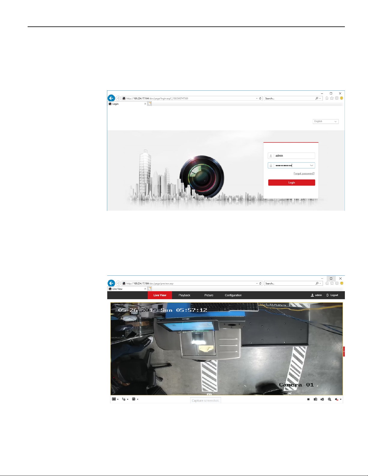
6. Access the camera view by doing the following:
a. Open a web browser.
b. Enter the IPAddress of the network camera in the address bar and press Enter
to access login interface.
c. Enter the following default login credentials:
Username: admin
Password: HikVision1
The browser opens a live feed of the camera, as shown in the image below.

7360-K068 Tri-Light/Lane Light with Camera Assembly and
Lane Light Label 5
7. Adjust the view of the camera to ensure that the following conditions are met:
• Customer's normal reach to Input and Bagwell areas are visible.
• Customer area is visible.
• Cart area is visible.
Note: Refer to the image below for an example of an ideal camera view. For the
purpose of illustration only, the image below shows a Right-hand (RH) orientation.
For more information on setting the camera parameters, refer to Hikvision Network
Camera User Manual.
Note: Ensure that the NCRCustomer Helpdesk is informed when the Tri-Light/Lane
Light with Camera is installed in the store.

67360-K068 Tri-Light/Lane Light with Camera Assembly and
Lane Light Label
Removing the Tri-Light/Lane Light (R6)
To remove the Tri-Light/Lane Light assembly, follow these steps:
1. Turn off the NCRSelfServ Checkout software and hardware systems. For more
information, refer to "General Operational Procedures" section of NCR SelfServ™
Checkout (7360) Hardware Service Guide (B005–0000–2378).
2. Remove the screw securing the Tri-Light/Lane Light assembly to the Tri-Light/Lane
Light pole.

7360-K068 Tri-Light/Lane Light with Camera Assembly and
Lane Light Label 7
3. Lift the Tri-Light/Lane Light assembly and then disconnect the cables.
Tip: Mark all cables as to where they are connected to quickly determine the
corresponding port when reconnecting the cables.
This manual suits for next models
1
Other NCR Camera Accessories manuals


Popular Camera Accessories manuals by other brands

Viltrox
Viltrox EF-NEX Mount instructions

Calumet
Calumet 7100 Series CK7114 operating instructions

Ropox
Ropox 4Single Series User manual and installation instructions

Cambo
Cambo Wide DS Digital Series Main operating instructions

Samsung
Samsung SHG-120 Specification sheet

Ryobi
Ryobi BPL-1820 Owner's operating manual


