NCT SC-32 User manual

SC-32
CNC LATHE
OPERATING MANUAL
NCT Ipari Elektronikai Kft. 1 / 29 Dátum: 2013.09.27.
1148 Budapest, Fogarasi út 7.
Tel.: 06-1-467-6300
www.nct.hu
SC-32
CNC LATHE
OPERATION MANUAL

SC-32
CNC LATHE
OPERATING MANUAL
NCT Ipari Elektronikai Kft. 2 / 29 Dátum: 2013.09.27.
1148 Budapest, Fogarasi út 7.
Tel.: 06-1-467-6300
www.nct.hu
CONTENTS
1. ACCURACY RECORD .................................................................................................... 2
2. SAFETY PRECAUTIONS ................................................................................................ 2
2.1. Safety Rules................................................................................................................. 2
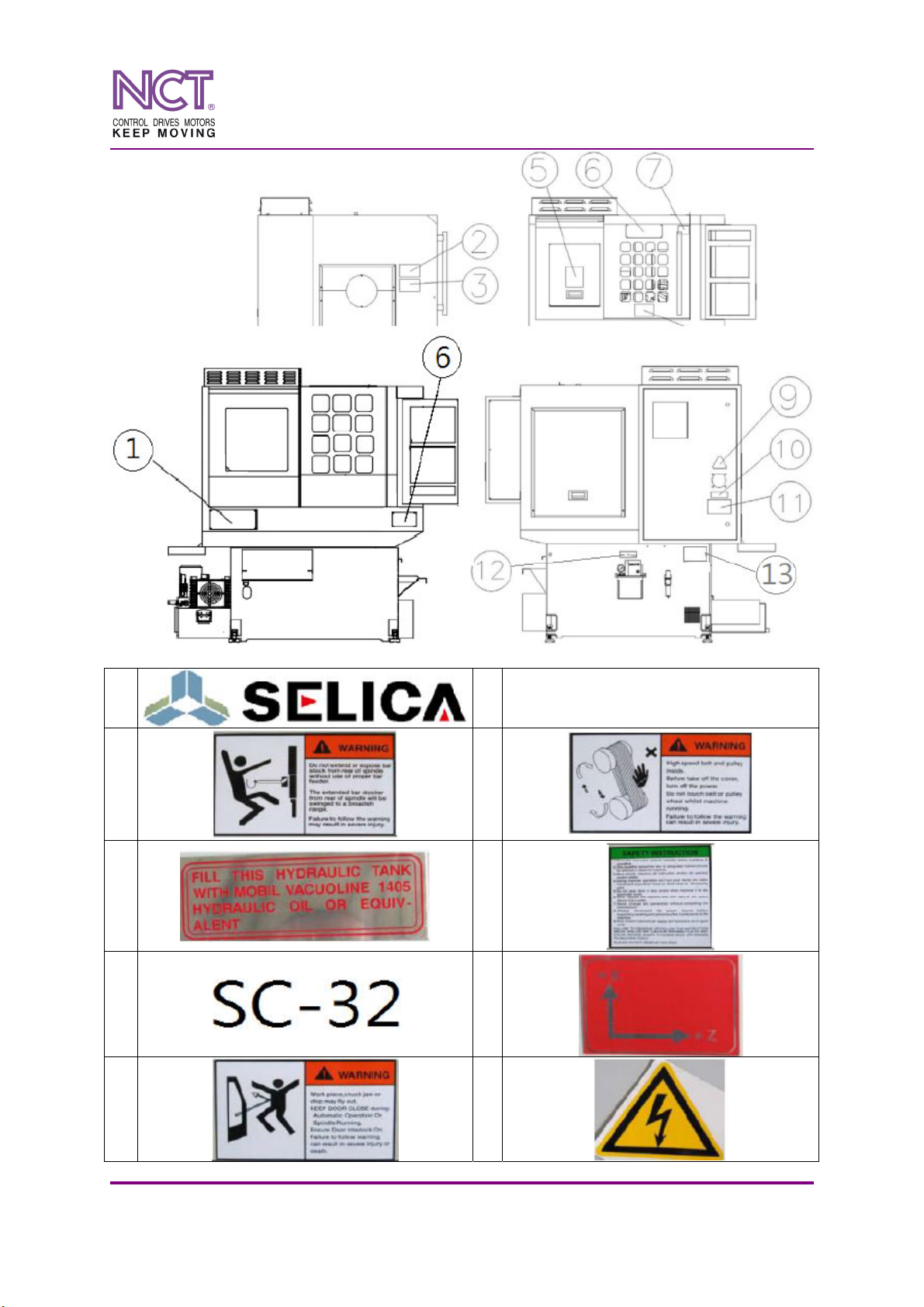
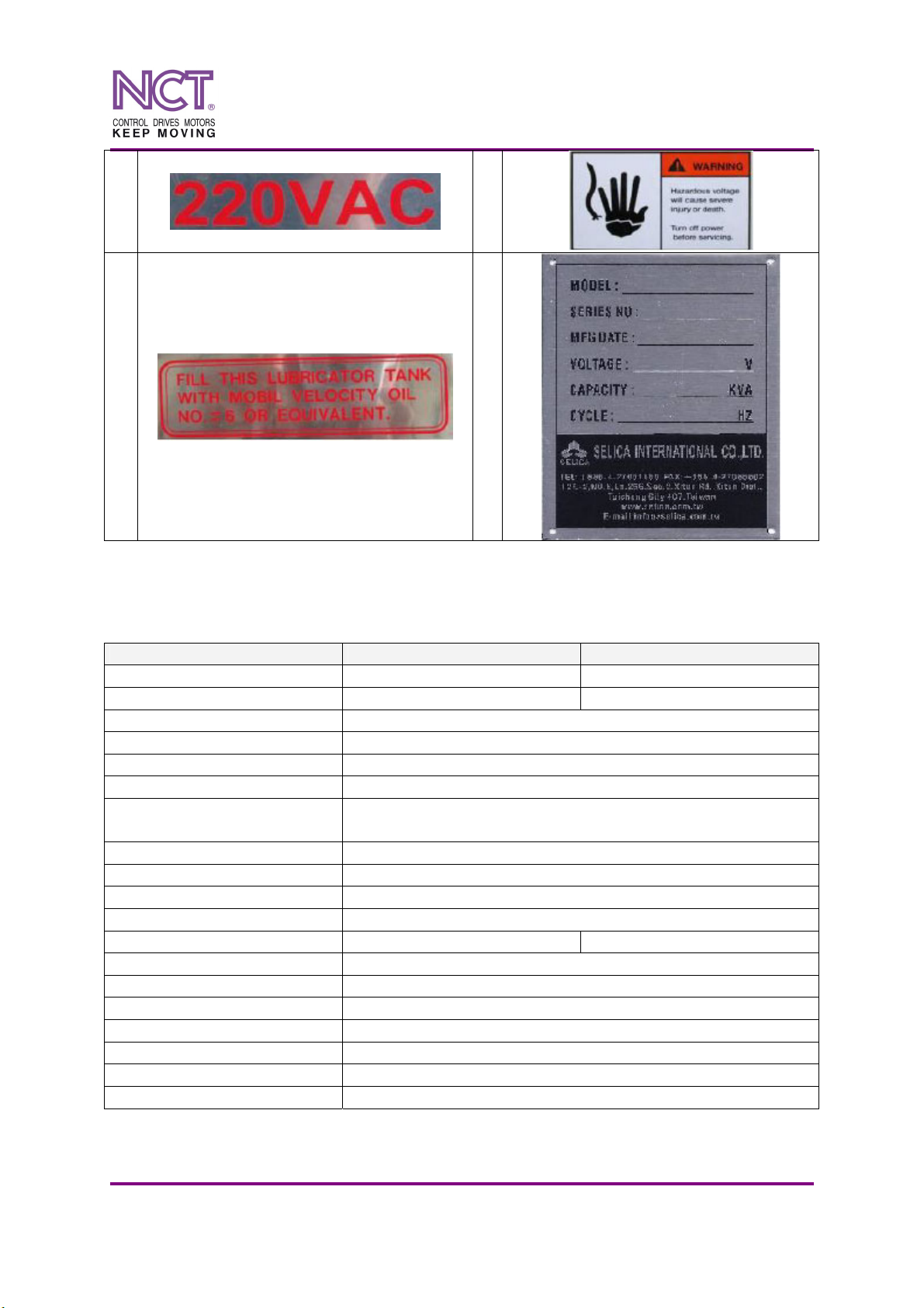
2.2. Warning label attaching positions ............................................................................... 2
3. DESCRIPTION OF THE MACHINE ............................................................................... 2
3.1. Specifications .............................................................................................................. 2
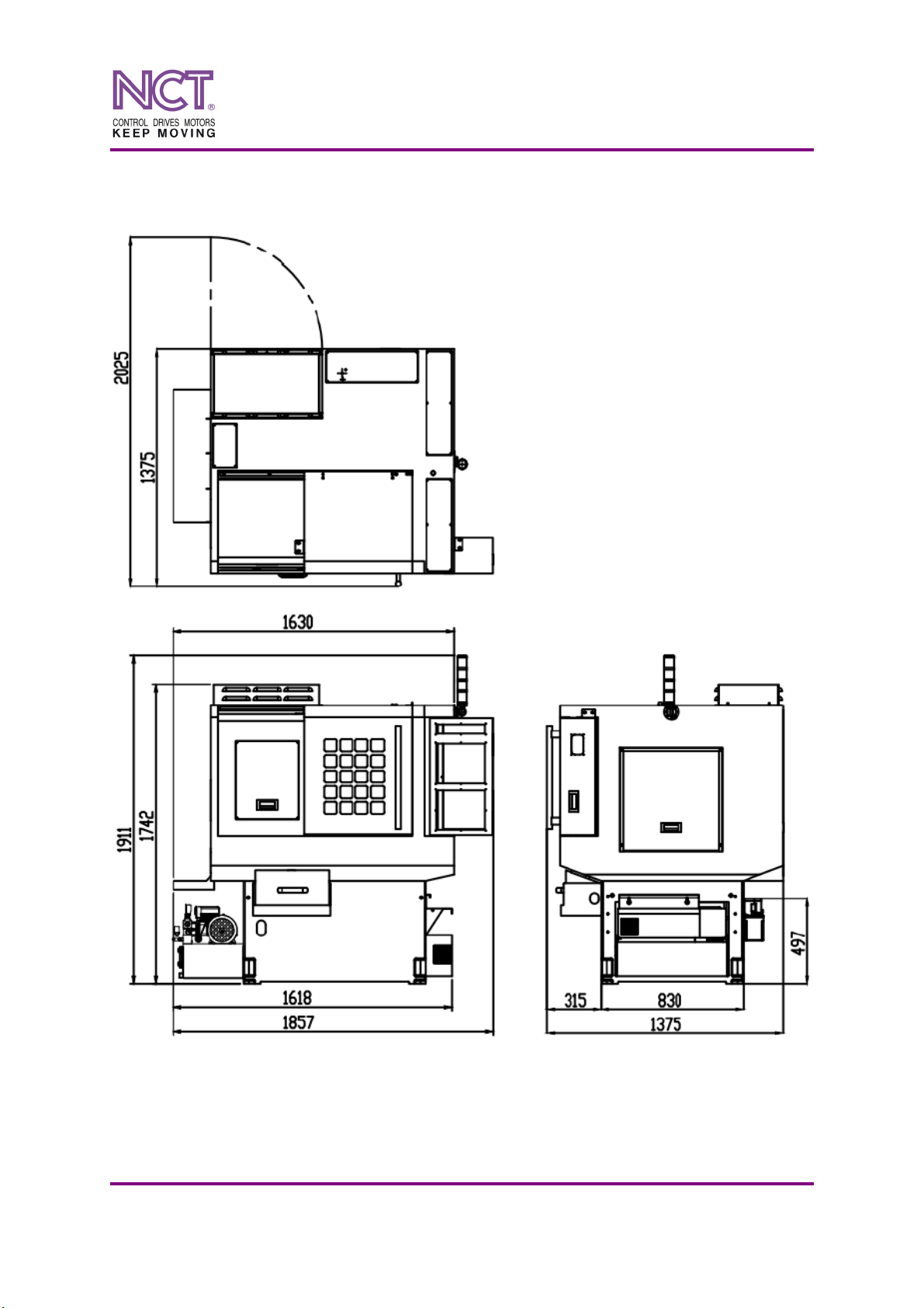
3.2. Machine overall dimensions........................................................................................ 2
3.3. Main components of the machine ............................................................................... 2
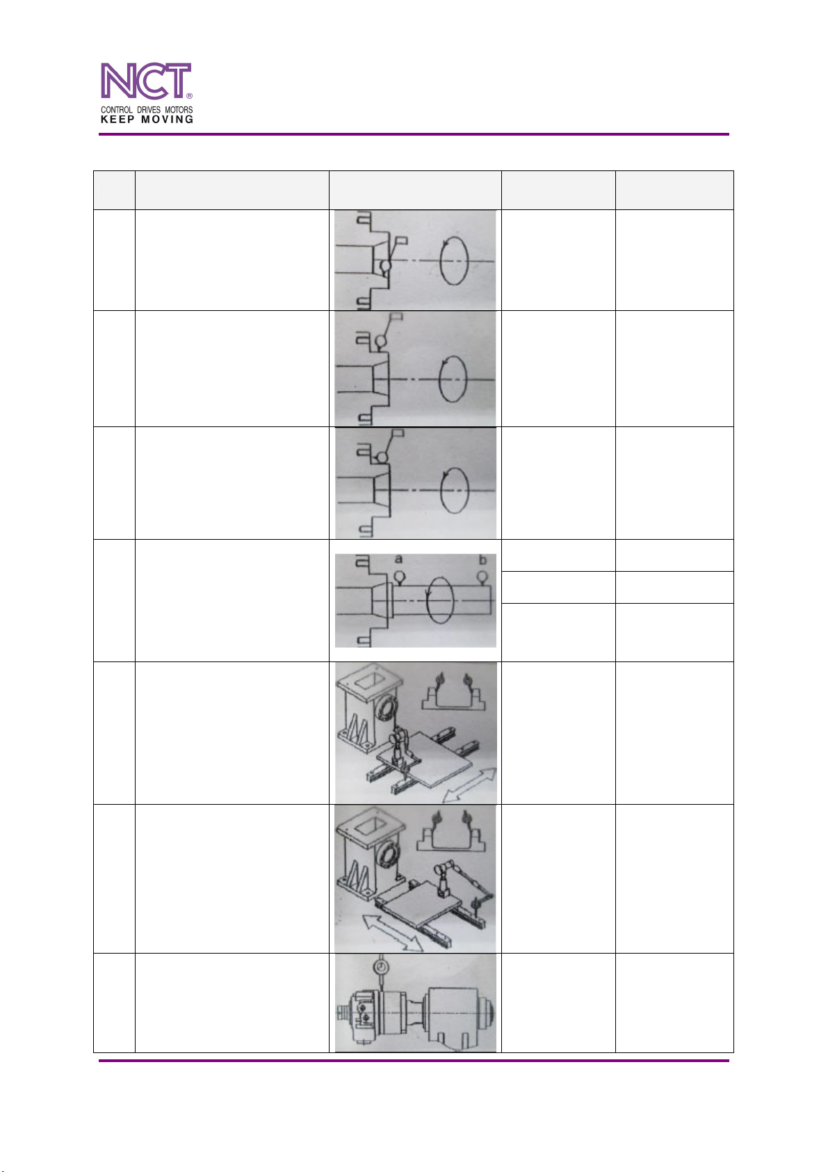
3.3.1. Spindle belt......................................................................................................... 2
3.3.2. Spindle collet...................................................................................................... 2
3.4. Recommended Spare Parts.......................................................................................... 2
3.5. Machinable materials .................................................................................................. 2
3.6. Machining capacity ..................................................................................................... 2
3.7. Movement.................................................................................................................... 2
3.8. Block position ............................................................................................................. 2
3.9. Installation................................................................................................................... 2
3.9.1. Power supply and environmental demand ......................................................... 2
3.9.2. Oil requirement .................................................................................................. 2
3.9.3. Maintenance ....................................................................................................... 2
3.10. Machine installation .................................................................................................... 2
3.10.1. Installation place ................................................................................................ 2
3.10.2. Machine cleaning ............................................................................................... 2
3.10.3. Installation steps................................................................................................. 2
3.10.4. Spindle speed setting.......................................................................................... 2
3.10.5. Precaution for program executing ...................................................................... 2
4. SUB-SYSTEMS.................................................................................................................2
4.1. Hydraulic system......................................................................................................... 2
4.2. Air pressure system ..................................................................................................... 2
4.3. Trouble shooting ......................................................................................................... 2
4.4. Three-jaw hydraulic chuck installation procedure ...................................................... 2
5. PART LIST ........................................................................................................................ 2
5.1. Base unit...................................................................................................................... 2
5.2. X-axis slide unit .......................................................................................................... 2
5.3. Z-axis slide unit........................................................................................................... 2
5.4. Spindle unit ................................................................................................................. 2
5.5. Tool unit ...................................................................................................................... 2
5.6. Coolant unit ................................................................................................................. 2
5.7. Side live tool................................................................................................................ 2
5.8. Front side live tool....................................................................................................... 2
5.9. Coolant tank unit .........................................................................................................2
5.10. Hydraulic unit.............................................................................................................. 2

SC-32
CNC LATHE
OPERATING MANUAL
NCT Ipari Elektronikai Kft. 3 / 29 Dátum: 2013.09.27.
1148 Budapest, Fogarasi út 7.
Tel.: 06-1-467-6300
www.nct.hu
1. ACCURACY RECORD
No. Parameter measured Illustration Tolerance
[mm]
Measuring
result [mm]
1 Radial run-out of the
spindle taper hole ≤ 0,005
2 Radial run-out of the
spindle nose ≤ 0,010
3 Axial run-out of the
spindle flange ≤ 0,015
a ≤ 0,005
b ≤ 0,005
4
Radial run-out of the
spindle hole (measured on
gauging mandrel) along
the length of
100 mm
5 Straightness of
the X axis slide way ≤ 0,005
6 Straightness of
the Z-axis slide way ≤ 0,005
7 Radial run-out of the
cylinder adapter ≤ 0,010

SC-32
CNC LATHE
OPERATING MANUAL
NCT Ipari Elektronikai Kft. 4 / 29 Dátum: 2013.09.27.
1148 Budapest, Fogarasi út 7.
Tel.: 06-1-467-6300
www.nct.hu
2. SAFETY PRECAUTIONS
2.1. Safety Rules
Please read carefully the following safety instructions in order to prevent personal
injuries and material damage.
– Do not install the machine near vibration and heat source, and on explosion dangerous
area.
– There shall be a fire extinguisher near the working place.
– The machine shall be connected to a 3Ph / 230 V/ 50 Hz power network.
– Just in case of running-down the accumulator, take a backward copy of all the parameters.
When the charging level of the accumulator is low, an alarm message will be displayed
on the screen. Charge the accumulator weekly.
– Any modification of the machine is prohibited.
– Before adjusting, checking and cleaning of the machine turn the main switch off.
– Before operating the machine check proper operation of the safety elements.
– Before operating the machine check the level and pressure of the coolant; improper use of
coolant can cause fire hazard.
– Before operating the machine close the door of the electric box in order to avoid electric
shock.
– Before operating the machine check the proper clamping and position of workpiece, tools
and attachments, and their balanced rotation.
– Before operating the machine close the door of the workspace; the door interlock device
protects the operator during operation of the machine. When the door is open the machine
can be hand-operated only. If the operator changes over to automatic operating mode, the
machine displays an error message and turns off the ‘Cycle Start’ knob.
– When the machine is running do not open the door and do not touch tools and workpiece.
– Running NC programs containing wrong parameters and values could cause several
failures.
– After maintenance procedure always do test run.
– During maintenance procedure, be careful with sharp components.
2.2. Warning label attaching positions
– Inside the electric box and the control there are high-voltage units there, improper
handling can cause electric shock; only well-trained serviceman and repairman is allowed
to enter into this space.
– Replace the label if it frays or disappears.

SC-32
CNC LATHE
OPERATING MANUAL
NCT Ipari Elektronikai Kft. 5 / 29 Dátum: 2013.09.27.
1148 Budapest, Fogarasi út 7.
Tel.: 06-1-467-6300
www.nct.hu
1
2
3
4
5
6
7
8
9

SC-32
CNC LATHE
OPERATING MANUAL
NCT Ipari Elektronikai Kft. 6 / 29 Dátum: 2013.09.27.
1148 Budapest, Fogarasi út 7.
Tel.: 06-1-467-6300
www.nct.hu
10
11
12
13
3. DESCRIPTION OF THE MACHINE
3.1. Specifications
SC-25 SC-32
Max. swing diameter Ø25 mm Ø32 mm
Three-jaw chuck dimension - Ø100 mm (0-3000 rpm)
Max. turning length 105 mm
Min. adjustable travel 0,001 mm
Tool shank dimension □12 mm or □16 mm
Max. drill bit diameter Ø20 mm
Number of tools turning tool, 6 pcs; boring tool, 4 pcs;
servo motor live tool, 1 pc (11 tools in all)
Max. spindle speed 6000 rpm
X-axis travel 345 mm
Z- axis travel 115 mm
X/Z-axis rapid feed 18 m/min
Spindle motor 3 kW 4 kW
X/Z motor 0,75 kW
Hydraulic pump motor 0,75 kW
Coolant pump motor 0,56 kW
Oil tank capacity 130 l
Machine overall dimensions 1830 x 1300 x 1760
Machine weight 1600 kg
Power supply AC / 3Ph / 220 V/ 8 kW

SC-32
CNC LATHE
OPERATING MANUAL
NCT Ipari Elektronikai Kft. 7 / 29 Dátum: 2013.09.27.
1148 Budapest, Fogarasi út 7.
Tel.: 06-1-467-6300
www.nct.hu
3.2. Machine overall dimensions

SC-32
CNC LATHE
OPERATING MANUAL
NCT Ipari Elektronikai Kft. 8 / 29 Dátum: 2013.09.27.
1148 Budapest, Fogarasi út 7.
Tel.: 06-1-467-6300
www.nct.hu
3.3. Main components of the machine
No. Title
1 Spindle motor
2 Basic seat
3 Slide set of Z-axis
4 Slide set of X-axis
5 Single hole attachment
6 Double hole attachment
7 O. D. Turning tool holder
8 Spindle

SC-32
CNC LATHE
OPERATING MANUAL
NCT Ipari Elektronikai Kft. 9 / 29 Dátum: 2013.09.27.
1148 Budapest, Fogarasi út 7.
Tel.: 06-1-467-6300
www.nct.hu
No. Title No. Title
1 Electric box 8 Coolant tank
2 Control panel 9 Power switch
3 Three-colour alarm lamp 10 Coolant pump motor
4 Machine main cover 11 Two-way component
5 Back side door of the spindle 12 Automatic lubrication oil filter
6 Activity door 13 Part collection box
7 Hydraulic tank
3.3.1. Spindle belt
Model Max. rpm Specification
SC-25 3000 rpm HTD-800-8M-23W
SC-32 3000 rpm HTD-800-8M-23W
3.3.2. Spindle collet
SC-25
FUJI #1825
Dimensions (steel):
d = 35 mm
L = 124 mm
D = 49 mm
α = 15°
M33 x 1,5

SC-32
CNC LATHE
OPERATING MANUAL
NCT Ipari Elektronikai Kft. 10 / 29 Dátum: 2013.09.27.
1148 Budapest, Fogarasi út 7.
Tel.: 06-1-467-6300
www.nct.hu
SC-32
FUJI #1832
Dimensions (steel):
d = 43 mm
L = 137 mm
D = 57,5 mm
α = 15°
M40 x 1,75
3.4. Recommended Spare Parts
– Spindle belt
– Fuse (8A, 4A)
– Proximity switch
3.5. Machinable materials
The machine is applicable to cut the following materials:
– General steel
– Normal iron
– Cast iron
– Aluminium alloy
– Copper-brass alloy
– Plastic
CAUTION! Other material should be selected carefully. Do not use this machine to cut
magnesium work-piece.
3.6. Machining capacity
– Straight turning
– Boring
– Drilling and tapping
– Cut off
– Inside and outside threading
– Arc and spherical turning
– Slotting (optional)

SC-32
CNC LATHE
OPERATING MANUAL
NCT Ipari Elektronikai Kft. 11 / 29 Dátum: 2013.09.27.
1148 Budapest, Fogarasi út 7.
Tel.: 06-1-467-6300
www.nct.hu
3.7. Movement
3.8. Block position

SC-32
CNC LATHE
OPERATING MANUAL
NCT Ipari Elektronikai Kft. 12 / 29 Dátum: 2013.09.27.
1148 Budapest, Fogarasi út 7.
Tel.: 06-1-467-6300
www.nct.hu
3.9. Installation
3.9.1. Power supply and environmental demand
Voltage of input power:
– AC 230V ± 10%
– 50 Hz ± 1%
– three-phase power network
– Recommend wire cable size – 6 - 8mm2
If the power source is higher or lower than above voltage, transformer shall be used to get
required voltage.
Power consumption: 10 kVA
Ground wire:
– The machine should be grounded by wire cable to PE terminal.
– The machine should be grounded suitably to prevent electric shock.
Environment requirements:
– Do not install the machine where it may be exposed to direct sunlight.
– Do not install the machine in uneven, vibrating, heated, and potentially explosive
area.
– Working area temperature: 0 - 45°C. Storage temperature: -20 - 60°C
– Humidity <30% (without air conditioner).
– Altitude Sea level: 1000 m.
– Setting machine in suitable place which keeps surrounding 1 m empty.

SC-32
CNC LATHE
OPERATING MANUAL
NCT Ipari Elektronikai Kft. 13 / 29 Dátum: 2013.09.27.
1148 Budapest, Fogarasi út 7.
Tel.: 06-1-467-6300
www.nct.hu
Levelling adjustment:
To keep the accuracy and to maintain the good condition of lifetime of this machine,
levelling adjustment is one of the important factors. Please carry out leveling by adjusting the
leveling bolts at the bottom of machine base after installation.
Please use accurate level 150 mm length with a minimum scale of 0.02 mm on the
worktable, and then turning the leveling bolts to make the deviation within 0.02 mm/M.
3.9.2. Oil requirement
Check point Supplied way Assigned oil Qty Using time
1 Spindle Daub by hand Grease - -
2 X/Z-axis
linear guide way Supply by lubricator Slide way oil G68 2 l
3 X/Z-axis
ball screw Supply by lubricator Slide way oil G68 2 l
When
lubricant
warning light
is on.
4 Milling device Supply by lubricator Slide way oil G68 2 l -
5 Chuck Daub by hand Normal use oil Proper -
6 Hydraulic system Inspect visibly Hydraulic oil 32#
(FINA) 20 l
Replace once
after first
month; then
replace once
every 6 month
7 Coolant Inspect visibly Cutting fluid SP-
M22 200 l -
8 Lubricant Inspect visibly Slide way oil G68
(FINA) 2 l -

SC-32
CNC LATHE
OPERATING MANUAL
NCT Ipari Elektronikai Kft. 14 / 29 Dátum: 2013.09.27.
1148 Budapest, Fogarasi út 7.
Tel.: 06-1-467-6300
www.nct.hu
Spindle
– Bearings in the spindle are forced lubricated the assembling by grease. This high-
speed grease is low-temperature and prolong, especially for high-speed rolling
bearings or high load.
– When the machine is not operated for a long time (more than 6 days), user should run
the spindle at low speed about 30 minutes before operation.
– Please not mix and use the specified oil above to avoid any possible damage to
machine. If not use our recommended oil, please read following remarks carefully.
Suggestion for coolant selection:
Ferrous materials: ARAL SAROL345
Cast iron: ARAL MULTROL 820
Any suitable coolant with no harm to health and not with low flash point. Any suitable
coolant that will not cause any paint peeling, rusting, and packing swelling by mixing with
lubricant.
It might result in corrosion of lubrication unit by mixing the lubricant with coolant or
hydraulic oil. The corrosion might cause lubrication failure, which, in turn, leads to
damages on the slide-way surfaces.
3.9.3. Maintenance
Frequency Inspection items
Daily
– Check oil level through the oil level gauge in the hydraulic
unit, slide-way lubrication oil tank.
– Check gripping pressure of the hydraulic power collets through
the oil level gauge.
– Check lubricated conditions of bed and slide-way surfaces.
– All safety devices.
Weekly – Clean and wash the filter of heat exchange. Shorter the clean
period if the surrounding full of dust.
Monthly – Check the bed-ways for level and straightness.
– Check all belts.
Every three month – Change X, Z-axis linear motion guide or slide-way.
Every six month – Change hydraulic oil in the hydraulic power unit.
– Check and adjust all of belt’s tension.
3.10. Machine installation
3.10.1. Installation place
Setting machine in suitable place which keeps surrounding 1 m empty.
3.10.2. Machine cleaning
All machine surfaces are covered with rust preservative, which must be thoroughly
cleaned before moving any parts of the machine. Only mild solvent and soft rags can be used
for cleaning.

SC-32
CNC LATHE
OPERATING MANUAL
NCT Ipari Elektronikai Kft. 15 / 29 Dátum: 2013.09.27.
1148 Budapest, Fogarasi út 7.
Tel.: 06-1-467-6300
www.nct.hu
3.10.3. Installation steps
– To remove all stopper used to prevent the machine moving in transportation and to check
if the machine is rusted, damaged, shape transformed, or broken, etc.
– Fix the leveling bolts and nuts.
– To check the power source is 3 phase 220V AC, if not, the transformer must be used.
– To connect the machine power with ground wire.
– To confirm the coolant tank is connected with coolant pipe.
– To check if all the safety devices are properly functional. Any fault must be corrected
before operating the machine.
– To fill in designated quantities of the specified oil to every reservoir.
– To check the indicator of the air and hydraulic pressure line is functional.
– To check the installed conditions of collet and tool. Any loose condition is not allowed.
– To confirm the tool /zero offset setting.
– To confirm the spindle speed and feed rate override dial settings; they must be 100%.
3.10.4. Spindle speed setting
The maximum spindle speed is 6,000 rpm. Never turn the spindle over 6,000 rpm. We
can control the maximum spindle speed by inputting command in G50 (TYPE A) in function
“Constant surface speed control”. For example, “G50 S5000”means the maximum spindle
speed is limited as 5,000 rpm. Remember to avoid any imbalance during rotating because
increased centrifugal force will reduce the clamping force.
3.10.5. Precaution for program executing
With a new program, never attempt to start actual cutting operation from the
beginning. First to run the program without setting a work-piece on the machine to check
machine operation and interference, after making sure that the work-piece can be cut without
problems in the single block mode operation or in MPG simulation mode operation, then the
automatic mode operation may be started. Remember to make sure that the work-piece is
securely clamped in the collet or clamp device.
Switch on the main power and press ‘POWER ON’. Take the reference points of all
axes and then warm up the machine for 15 minutes.

SC-32
CNC LATHE
OPERATING MANUAL
NCT Ipari Elektronikai Kft. 16 / 29 Dátum: 2013.09.27.
1148 Budapest, Fogarasi út 7.
Tel.: 06-1-467-6300
www.nct.hu
4. SUB-SYSTEMS
4.1. Hydraulic system
Hydraulic unit is used for chuck open and close. Please make sure the pressure is in
the right range, otherwise it will result in abnormal damage to the machine.
Hydraulic unit pump pressure range: 25-35 kg/cm²
Hydraulic unit chuck pressure range: 10-30 kg/cm²

SC-32
CNC LATHE
OPERATING MANUAL
NCT Ipari Elektronikai Kft. 17 / 29 Dátum: 2013.09.27.
1148 Budapest, Fogarasi út 7.
Tel.: 06-1-467-6300
www.nct.hu
4.2. Air pressure system
Pressure source is used for open and close of the income feeder and blowing device.
Please make sure the pressure is in the right range, otherwise it will result in abnormal
damage to the machine.
Air source pressure range: 4-7 kg/cm²

SC-32
CNC LATHE
OPERATING MANUAL
NCT Ipari Elektronikai Kft. 18 / 29 Dátum: 2013.09.27.
1148 Budapest, Fogarasi út 7.
Tel.: 06-1-467-6300
www.nct.hu
4.3. Trouble shooting
1. Rotary cylinder doesn’t work
a) Stop the spindle if it is still running
b) Raise the hydraulic pressure to approx. 5kg/cm.sq, and to switch the collet clamping
ON/OFF, then to confirm cylinder motion again.
c) If the cylinder still doesn’t work, to increase the pressure gradually (by approx.
5kg/cm.sq each time) and repeat the same procedures as described in b), then to
confirm the cylinder motion. The maximum collet pressure is 30% increasing. If the
cylinder works in normal operation, return the pressure to original set.
d) If cylinder still doesn’t work after above procedures, please turn off the power. Then
wait till the cylinder temperature is as down as surroundings and repeat the procedures
above to recheck the cylinder motion.
e) If the cylinder doesn’t work after above procedures, please dismount the draw-bar nut
and take off the cylinder unit to check the motion.
2. Piston doesn’t work
a) Check all pressure hose with hydraulic pressure.
b) Check if all the connected pipes are correct.
c) After remedy or correct the connection, please re-do above procedure.
3. Insufficient pressure
a) Apply a pressure gauge near the inlet of cylinder to check if the pressure follows the
specified value.
b) If the drain flow is more than normal, it is possible that the inside O-ring is wearing
away. Replace it then check again.
4. Pump noise
a) Avoid air suction.
b) Check the hydraulic oil level and refill it.
c) Clean the filter and remove the dirt inside oil tank.
d) Pump was worn away.
4.4. Three-jaw hydraulic chuck installation procedure
a) Shift the tool slide on Z-axis slide base back from spindle a length, then lock it after
adjusting the parallelism of the tool slide and the spindle by dial indicator.
b) Assemble the three-jaw hydraulic chuck on the spindle.
c) Replace the draw bar, ring, spindle pulley, and belt (6000 rpm→3000 rpm) for three-
jaw chuck.
C32 - collet C32 - three-jaw chuck Description
6000 3000 Spindle maximum speed, rpm
4500 1200 Spindle acceleration time, ms

SC-32
CNC LATHE
OPERATING MANUAL
NCT Ipari Elektronikai Kft. 19 / 29 Dátum: 2013.09.27.
1148 Budapest, Fogarasi út 7.
Tel.: 06-1-467-6300
www.nct.hu
5. PART LIST
NOTE: The part list of the Manufacturer’s original manual does not use the number 8
for numbering the main parts.

SC-32
CNC LATHE
OPERATING MANUAL
NCT Ipari Elektronikai Kft. 20 / 29 Dátum: 2013.09.27.
1148 Budapest, Fogarasi út 7.
Tel.: 06-1-467-6300
www.nct.hu
5.1. Base unit
No. Title
1.1 Base fixing block
1.2 Base
Table of contents
Other NCT Lathe manuals
Popular Lathe manuals by other brands

Jet
Jet JWL-1220 brochure

HENNESSY INDUSTRIES
HENNESSY INDUSTRIES Ammco 800 Safety Instructions, Installation Instructions, Operating Instructions, Maintenance Instructions

Hafco Woodmaster
Hafco Woodmaster T-13S Operation manual

Ryobi
Ryobi ML618 Owner's operating manual

AMP
AMP Mitre-Mite VN4 MemoryProgram instruction manual

Klutch
Klutch 49679 owner's manual

Cassese
Cassese CS 940 user & parts manual

The Beall Tool Company
The Beall Tool Company The Lathe Wizard Setting up

Baileigh Industrial
Baileigh Industrial WL-1847VS Operator's manual

Jet
Jet BD-11G operating manual

Delta
Delta 46-715 instruction manual

Jean Lebeniste
Jean Lebeniste MC1100B instruction manual