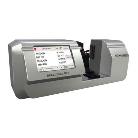
NDC BenchMike Pro manual

BenchMike Pro &
Z-Mike Pro
Benchtop Laser Micrometer
Instruction Handbook
NDC Technologies
8001 Technology Blvd.
Dayton, Ohio 45424
© 2017 NDC Technologies
NDC Technologies
Dayton, Ohio 45424
© 2017 NDC TechnologiesNDC
Technologies
Tel: +1-937-233-9936
Fax: +1-937-233-7284
www.ndc.com/betalasermike
Making Light Work
ment

Proprietary Notice
The information and design disclosed herein were originated by and are the property of NDC Technologies.
NDC Technologies reserves all patent, proprietary design, manufacturing, reproduction use, and sales rights
thereto, and to any article disclosed therein, except to the extent rights are expressly granted to others. The fore-
going does not apply to vendor proprietary parts.
In-line with NDC’s policy of continuous improvement, the information contained in this document may change to
allow the introduction of design improvements.
NDC BenchMike Pro 2025/2050 & Z-Mike Pro
Instruction Handbook
Part Number: MAN/EN5008-0092
Revision: B
Date of Release: January, 2018

Contact NDC
Online Support
You can access the NDC Customer Support portal, myNDC at https://ndc.custhelp.com.
myNDC is a cloud-based portal that allows you to get product support by phone, ask a question, provide feed-
back, submit an RMA request or access information in our on-line knowledge database. You can browse the
myNDC site or create a myNDC account.
To create a myNDC account, click the Log in or Sign up button. After creating the account, you will be
immediately logged in. To log in on subsequent visits to myNDC, click the Log in or Sign up button, en-
ter your user name and password, and then click Log in.
To submit an RMA, click on the RMA Request tab and follow the on-screen instructions.

NDC Contact Numbers
Please have your sales order number at hand before contacting NDC.
−Beta LaserMike Gauges
Beta LaserMike Gauges
Americas
+1 937 233 9935
Asia Pacific
India: +91-124-2789507
Alternative number +91-124-2789508
Japan: +81 (0)3 3255 8157
All other countries: +1 937 233 9935
Alternative number +44 1621 852244
China
+86 21 61133609
EMEA
(Europe,
Middle East,
Africa)
Germany: 0800 1123194
France: 0810 600 400
Italy: +39 0331 454 207
All other countries (English speaking):
+44 1621 852244
Please select option 3 to be
connected to the service team

BenchMike Pro 2025/2050 & Z-Mike Pro 4025/4050 Instruction Handbook: Caution i
Caution
If the equipment is not used in the manner specified by NDC
Technologies, the protection provided by the equipment
may be impaired.
FCC Manual Digital
Devices Statement
Note: This equipment has been tested and found to comply
with the limits for a Class A digital device, pursuant to part
15 of the FCC Rules. These limits are designed to provide
reasonable protection against harmful interference when the
equipment is operated in a commercial environment. This
equipment generates, uses, and can radiate radio frequency
energy and, if not installed and used in accordance with the
instruction manual, may cause harmful interference to radio communications. Operation of the equipment in a
residential area is likely to cause harmful interference, in which case, the user will be required to correct the inter-
ference at his own expense.

ii BenchMike Pro 2025/2050 & Z-Mike Pro 4025/4050 Instruction Handbook: Table of Contents
Table of Contents
1INTRODUCTION................................................................................................................................. 1-1
1.1 BENCHMIKE PRO OPTIONS......................................................................................................... 1-1
1.1.1 Laser Beam Options........................................................................................................ 1-1
1.1.2 Interfaces......................................................................................................................... 1-1
1.1.3 Accessories ..................................................................................................................... 1-1
1.1.4 Measurement Fixtures..................................................................................................... 1-1
1.2 CALIBRATION............................................................................................................................. 1-2
1.3 USING THE BENCHMIKE PRO...................................................................................................... 1-2
1.4 MEASURING A PRODUCT ............................................................................................................ 1-3
1.4.1 Sources of Error .............................................................................................................. 1-4
1.4.2 Measuring Transparent Products.................................................................................... 1-4
1.5 DATA PROCESSING AND DISPLAY................................................................................................ 1-5
1.6 LASER SAFETY........................................................................................................................... 1-6
1.6.1 Output Beam Data........................................................................................................... 1-7
1.6.2 Warning Information ........................................................................................................ 1-7
2INSTALLATION.................................................................................................................................. 2-1
2.1 INSTRUCTIONS........................................................................................................................... 2-1
2.1.1 Power............................................................................................................................... 2-1
2.1.2 Lifting............................................................................................................................... 2-1
2.1.3 Location........................................................................................................................... 2-1
2.1.4 Ventilation Requirements ................................................................................................ 2-1
2.1.5 Equipment Maintenance.................................................................................................. 2-1
2.1.6 Caution Symbol ............................................................................................................... 2-2
2.2 DRAWINGS................................................................................................................................. 2-2
2.2.1 Model 2025...................................................................................................................... 2-2
2.2.2 Model 2050...................................................................................................................... 2-4
2.3 CONNECTIONS........................................................................................................................... 2-6
2.3.1 Connecting the BenchMike Pro to Your PC .................................................................... 2-6
2.3.2 Digital I/O Connector ....................................................................................................... 2-6
2.3.3 Connecting to Digital Inputs............................................................................................. 2-8
2.3.4 Connecting to Digital Outputs with the BenchMike Pro +12V Supply............................. 2-8
2.3.5 Connecting to Digital Outputs with an External Supply................................................... 2-9
2.3.6 Serial Connector.............................................................................................................. 2-9

BenchMike Pro 2025/2050 & Z-Mike Pro 4025/4050 Instruction Handbook: Table of Contents iii
2.3.7USB Printer Connector.................................................................................................. 2-10
2.3.8 USB Serial Connector ................................................................................................... 2-10
2.3.9 Ethernet RJ45 Connector.............................................................................................. 2-10
2.3.10 Fixture Connector.......................................................................................................... 2-10
2.3.11 Connecting to a Quadrature Encoder............................................................................ 2-11
2.4 ADDING A NETWORK PRINTER .................................................................................................. 2-12
2.4.1 Requirements ................................................................................................................ 2-12
2.4.2 Procedure...................................................................................................................... 2-12
2.5 ADDING A USB PRINTER .......................................................................................................... 2-17
2.5.1 Requirements ................................................................................................................ 2-17
2.5.2 Procedure...................................................................................................................... 2-17
3WORKHOLDING FIXTURES ............................................................................................................. 3-1
3.1 ERROR SIGNALS ........................................................................................................................ 3-1
3.2 INTELLIGENT AND NON-INTELLIGENT FIXTURES............................................................................ 3-1
3.2.1 Non-Intelligent Fixture: Linear (Slide) Position................................................................ 3-1
3.2.2 Intelligent Fixture: Rotary/Linear Fixture Position............................................................ 3-2
3.3 DESCRIPTION OF FIXTURES ........................................................................................................ 3-2
3.3.1 General Purpose Fixed V-Block Fixture.......................................................................... 3-2
3.3.2 Universal Slide Fixture..................................................................................................... 3-3
3.3.3 Digital Readout (DRO) Slide Fixture ............................................................................... 3-7
4SETUP ................................................................................................................................................ 4-1
4.1 SETTING UP THE BENCHMIKE PRO ............................................................................................. 4-1
4.1.1 Turning Power On ........................................................................................................... 4-1
4.1.2 Using the Three Data Buttons......................................................................................... 4-1
4.1.3 Touch Screen Layout ...................................................................................................... 4-1
4.2 MODE ICON AND MENU............................................................................................................... 4-4
4.3 FEATURE ICON........................................................................................................................... 4-5
4.4 MEASUREMENT ICON.................................................................................................................. 4-6
4.5 SETUP MENU............................................................................................................................. 4-7
4.6 SYSTEM FUNCTIONS .................................................................................................................. 4-7
4.6.1 Communication Ports .................................................................................................... 4-11
4.6.2 Sleep and Shutdown functions...................................................................................... 4-13
4.7 LIBRARY FUNCTIONS................................................................................................................ 4-14
4.8 SETTINGS FUNCTIONS.............................................................................................................. 4-16
4.8.1Sample Report............................................................................................................... 4-18
4.8.2 Batch Report.................................................................................................................. 4-19

iv BenchMike Pro 2025/2050 & Z-Mike Pro 4025/4050 Instruction Handbook: Table of Contents
4.8.3 Fixture Sample Report................................................................................................... 4-20
4.8.4 Fixture Batch Report...................................................................................................... 4-21
4.8.5 Rotating Fixture Batch Report Data Flow...................................................................... 4-22
4.8.6 Serial Data Out Format.................................................................................................. 4-23
4.8.7 SQC Batch Setup .......................................................................................................... 4-24
4.8.8 Environmental Compensation Setup............................................................................. 4-24
4.8.9 Units/Res/Rounding....................................................................................................... 4-25
4.9 FEATURE FUNCTIONS............................................................................................................... 4-26
4.10 MEASUREMENT FUNCTIONS...................................................................................................... 4-28
4.10.1 Expression Editor .......................................................................................................... 4-28
4.10.2 Fixture Menu.................................................................................................................. 4-28
4.10.3 Measurement Type........................................................................................................ 4-30
4.10.4 Measurement Method.................................................................................................... 4-31
4.10.5 Part Mode...................................................................................................................... 4-31
4.10.6 Nominal/Limits/Tolerance Setup.................................................................................... 4-32
4.10.7 Floating Nominal............................................................................................................ 4-33
4.10.8 Master Measurement..................................................................................................... 4-33
4.11 DATA FUNCTIONS..................................................................................................................... 4-34
4.12 SAVE FUNCTION....................................................................................................................... 4-38
4.13 STATUS MENUS ....................................................................................................................... 4-39
4.14 SECURITY SETUP..................................................................................................................... 4-42
4.14.1 Entering the System Password ..................................................................................... 4-43
4.14.2 Security Page ................................................................................................................ 4-43
4.14.3 Lock Page...................................................................................................................... 4-43
4.14.4 Screen Configuration..................................................................................................... 4-44
4.14.5 Scanner Configuration................................................................................................... 4-44
4.14.6 Scan Errors Configuration ............................................................................................. 4-44
4.14.7 International Configuration ............................................................................................ 4-44
4.14.8 Options 1: Reports......................................................................................................... 4-45
4.14.9 Options 2: Graphs ......................................................................................................... 4-45
5ADVANCED CAPABILITIES.............................................................................................................. 5-1
5.1 EXPRESSION EDITOR ................................................................................................................. 5-1
5.1.1 Components of the Expressions ..................................................................................... 5-1
5.2 ADVANCED SCREEN CAPABILITIES .............................................................................................. 5-5
5.2.1 Accessing Advanced Capabilities ................................................................................... 5-5
5.2.2 Tolerance and Limit Checking Display Capabilities ........................................................ 5-7

BenchMike Pro 2025/2050 & Z-Mike Pro 4025/4050 Instruction Handbook: Table of Contents v
5.3 CUSTOM MEASUREMENTS.......................................................................................................... 5-7
5.3.1 Custom Measurement Properties.................................................................................... 5-9
5.4 USING A FOOTSWITCH.............................................................................................................. 5-10
6REMOTE SETUP................................................................................................................................ 6-1
6.1 WHAT IS PURL?........................................................................................................................ 6-1
6.1.1 Non-Printable Characters................................................................................................ 6-1
6.2 COMMAND FORMAT.................................................................................................................... 6-2
6.2.1 Messages to the BenchMike Pro Without the Wrapper .................................................. 6-2
6.2.2 Messages from the BenchMike Pro without the Wrapper............................................... 6-3
6.2.3 Messages to the BenchMike Pro with the Wrapper ........................................................ 6-3
6.2.4 Messages from the BenchMike Pro with the Wrapper.................................................... 6-4
6.2.5 Prefix Setting ................................................................................................................... 6-9
6.3 COMMAND DESCRIPTIONS........................................................................................................ 6-10
6.3.1 Configure Settings......................................................................................................... 6-10
6.3.2 Getting Help................................................................................................................... 6-18
6.3.3 Performing Measurements ............................................................................................ 6-18
6.3.4 Checking System Status and Configuring Libraries...................................................... 6-19
6.4 TABLE OF COMMANDS.............................................................................................................. 6-23
7SERVICING YOUR EQUIPMENT ...................................................................................................... 7-1
8SPECIFICATIONS.............................................................................................................................. 8-1
8.1 OPERATIONAL SPECIFICATIONS .................................................................................................. 8-1
8.2 PERFORMANCE SPECIFICATIONS................................................................................................. 8-1
8.2.1 General BenchMike Pro Specifications (2025 and 2050) ............................................... 8-1
8.2.2 BenchMike Pro Model 2025 Specifications1.................................................................... 8-2
8.2.3 BenchMike Pro Model 2050 Specifications1.................................................................... 8-2
8.2.4 Z-Mike Pro Model 4025 Specifications1........................................................................... 8-3
8.2.5 Z-Mike Pro Model 4050 Specifications1........................................................................... 8-3
8.3 DRAWINGS................................................................................................................................. 8-4
8.3.1 Model 2025...................................................................................................................... 8-4
Model 2050................................................................................................................................... 8-5
8.4 LASER BEAM OPTIONS ............................................................................................................... 8-5


CHAPTER
1
BenchMike Pro 2025/2050 & Z-Mike Pro 4025/4050 Instruction Handbook: Introduction 1-1
1 Introduction
1.1 BenchMike Pro Options
The Model 2025 BenchMike Pro covers the measurement range 0.003-1.00 inch, and the Model 2050 BenchMike
Pro covers the measurement range 0.010-2.00 in. There are five types of optional BenchMike Pro equipment.
1.1.1 Laser Beam Options
There are wide beam options for all BenchMike Pro models which permit the measurement of rough surfaces. A
small spot size option is also available for the Model 2025 to measure small diameters and part features down to
0.001 inch (25.4 µm).
1.1.2 Interfaces
The following input and output interfaces are ordered as options to the standard BenchMike Pro, allowing you to
customize your micrometer to your specific needs: 8 digital inputs and 12 digital outputs, 1 stepper motor port, a
second quadrature encoder input, and footswitch input.
1.1.3 Accessories
Accessories to the BenchMike Pro include footswitch, and dust cover.
1.1.4 Measurement Fixtures
Work holding fixtures such as universal slides, v-blocks, adjustable centers, leadscrew positioners, rotary chucks,
concentricity fixtures, and positioning tables are available for the BenchMike Pro, as described in the Workholding
Fixtures section.

1-2 BenchMike Pro 2025/2050 & Z-Mike Pro 4025/4050 Instruction Handbook: Introduction
1.2 Calibration
Each BenchMike Pro is calibrated at the factory using specialized NDC Technologies equipment. This calibration
is performed with N.I.S.T. (National Institute of Standards and Technology) traceable calibration gauges in an en-
vironmentally-controlled laboratory to ensure optimal performance.
Before a certificate of calibration is issued, each of the following procedures is performed at the factory:
External optics are cleaned
Internal optics are cleaned
Multiple mastered points are used to enhance accuracy
Test points and power supply voltages are verified
Optics are aligned
Scan-across test is performed to verify accuracy at several hundred points
Repeatability test is performed to determine short-term measurement stability
Drift test is performed to determine long-term measurement stability
Multi-point performance test is performed with a V-block
In order to ensure the measurement accuracy shown in the Specifications, it is recommended that you have your
BenchMike Pro calibrated by NDC Technologies once per year. While at the factory, NDC Technologies can also
perform any required retrofits, repairs, or upgrades.
1.3 Using the BenchMike Pro
To turn on the BenchMike Pro, push the power button on the rear of the
unit. It will take about one minute for the unit to initialize.
To turn off the BenchMike Pro, push the power button for one second.
The BenchMike Pro will begin the power-down cycle. Holding down the
power button for five seconds will immediately turn off the unit.
When the BenchMike Pro is turned on, the last saved configuration is
displayed on the touch screen. The graphical user interface includes a touch screen which allows the screen to be
used to select items. Use your finger to select commands, menus, help, or enter numbers.
To avoid scratching the coating on the touch screen, do not use any sharp object on the display. Remember to
clean the screen regularly, using a household window cleaner. Ensure that the lower rim of the screen is kept
clean of dust and other contaminants to avoid degrading the gasket around the display.

BenchMike Pro 2025/2050 & Z-Mike Pro 4025/4050 Instruction Handbook: Introduction 1-3
1.4 Measuring a Product
The BenchMike Pro measures a part by sweeping a beam of laser light across its measurement area. Each
sweep of the beam is called a scan. The BenchMike Pro scans the part 100 times per second.
As the beam sweeps through the BenchMike Pro’s measure-
ment area, it is alternately blocked by the part, or allowed to
pass through to the receive side of the BenchMike Pro. This
breaks each scan up into segments of light (when the beam
passes over the product) and dark (when the beam is blocked
by the product). The BenchMike Pro measures the diameter of
a part by detecting the size of this “shadow” (dark segment)
created by the part.
Note: The number of segments created by the laser beam will
vary based on the number of part(s) placed in the measurement area.
In general, you can measure an object placed in the scanning laser beam if it creates a “shadow”. However, to
obtain maximum accuracy, a certain portion has been defined as the measurement area. This area represents the
location where specifications apply and performance is consistent with factory calibration and alignment.
The measurement area surrounds the Pass Line of the gauge and covers of the full measurement range of the
unit (1.0 in. for the Model 2025 and 2.0 in. for the Model 2050). The Pass Line of the gauge is located halfway
between the transmitter and the receiver. These areas are de-
fined as follows:
Model 2025: ±0.030 in. from the Pass Line
Model 2050: ±0.060 in. from the Pass Line
You will obtain the most accurate measurements from your
BenchMike Pro when the part is placed in this area.
Note: Specifications apply at the intersection of the Scan Centerline and the Pass Line.

1-4 BenchMike Pro 2025/2050 & Z-Mike Pro 4025/4050 Instruction Handbook: Introduction
1.4.1 Sources of Error
Please note that any motion of the part, while in a fixture or not, can induce measurement error.
Be conscious of the following potential sources of error during measurement.
Dust or film on the measured object will produce measurements greater than the actual size. Wipe oily or dusty
objects with a cloth before measuring them.
Dust or contamination on the transmitter or receiver scan window will also
produce incorrect measurements. Follow the cleaning procedure de-
scribed later in this manual as part of a routine maintenance program.
Incorrectly placing the object in the measurement area will also produce
incorrect measurements. Place the measured object perpendicular to the
scanning laser beam, and avoid tilting the measured object vertically with
respect to the scan path. The greater the object’s angle, the greater the
measurement error.
Temperature variations (see Troubleshooting section in the Operator
Guide) will cause expansion or contraction of the part. Accurate temperature measurements are necessary to
compensate for changes in product size.
As an object moves within the measurement area, certain errors will become more prominent, depending on the
direction and magnitude of this motion. In general, measurements are less affected by motion along the Scan
Centerline than by motion along the Pass Line.
1.4.2 Measuring Transparent
Products
The BenchMike Pro can measure transparent products when
a Transparent Object Measurement type (Types 51, 52, and
53) is selected. See section in Setup about Measurement
Types for more information. Note that these measurement
types are not available on all BenchMike Pros.
Although an opaque product blocks laser light across its en-
tire diameter, a transparent product allows some laser light to pass through.
Since the BenchMike Pro determines product size based on the sharp increases and decreases in gathered laser
light, it may incorrectly determine product diameter for transparent products unless Transparent Object Measure-
ment has been installed.

BenchMike Pro 2025/2050 & Z-Mike Pro 4025/4050 Instruction Handbook: Introduction 1-5
The drawings to the right show sample oscilloscope wave-
forms from the measurement of an opaque product and a
transparent product. For the opaque product, the BenchMike
Pro can easily determine the width of the product since the
waveform drops sharply and rises sharply at the edges of the
product. For the transparent product, however, laser light
passes through the product and the behavior of the light be-
tween the first sharp drop and last sharp rise must be ig-
nored. With the Transparent Object Measurement option, the
product diameter is based on the first sharp drop in laser light
and the last sharp rise, resulting in a correct calculation of the
diameter.
Note that having a clean product is essential for attaining an
accurate measurement in these modes.
1.5 Data Processing and Display
The BenchMike Pro allows you great flexibility in controlling the way data is displayed and processed. As de-
scribed in the Advanced Capabilities section, there are several parameters which can be used to control the aver-
aging of measurements, the number of digits displayed on the screen, the format of printed reports, etc. The
BenchMike Pro has been specifically designed to allow you to customize your measurement display and data
processing simply and for your specific needs and preferences.
Each sweep of the laser beam across the measurement area is called a scan, and the BenchMike Pro scans the
part 100 times per second. Scans are collected to compute a reading for a given sample. The Averaging Rate
parameter determines how many scans (or time length in seconds) are averaged to compute one reading.
Although each scan received from the BenchMike Pro includes enough information to compute a size value, ac-
curacy and repeatability are increased significantly if a number of scans are collected and averaged. Scans can
be taken of individual samples or continuous products, as defined on the Measurement Setup page. For individual
samples, an Averaging Rate value of 200 scans is typical. For continuous products, an appropriate value should
be determined experimentally for the particular application.

1-6 BenchMike Pro 2025/2050 & Z-Mike Pro 4025/4050 Instruction Handbook: Introduction
The average of all the readings taken during a batch is calculated,
along with the standard deviation. The standard deviation is a
measure of how the individual sample values varied during the
batch. The standard deviation value indicates whether samples
were evenly distributed over a wide range of values or whether most
samples were grouped around the average value. The diagram to
the right shows two sample normal distributions.
The drawing to the right shows a normal distribution of data. A nor-
mal distribution is one in which 99.73% of all
values fall within ±3 standard deviations of
the average.
1.6 Laser Safety
The BenchMike Pro uses a Collimated Diode laser which emits red light at a wavelength of 635nm, while the Z-
Mike Pro uses a Helium-Neon gas laser, which emits light at a wavelength of 632.8nm. In each case, no invisible
or otherwise harmful radiation is emitted.
The radiant output power of the internal laser and of the entire BenchMike Pro is relatively low. The laser beam
will not harm your skin, and your eyes are protected by a natural aversion response that will cause you to blink or
look away. However, the laser light emitted from the BenchMike Pro should be treated with caution and common
sense. Do not attempt to look into the BenchMike Pro, and avoid staring at reflections of the beam.
The American National Standard for the Safe Use of Lasers (ANSI Z136.1—1993) classifies this laser product as
Low Power —Class II and provides reasonable and adequate guides for its safe use. The user of the BenchMike
Pro and other personnel responsible for its safe use should consult this ANSI standard. It is available from:
American National Standards Institute
1430 Broadway
New York, New York 10018
The Center for Devices and Radiological Health (CDRH) of the Food and Drug Administration has established
regulations for manufacturers of laser products. All laser products sold in the U.S.A. since August, 1976 must be
certified by the manufacturer as meeting certain product performance (safety) standards, and each laser must
bear a label indicating compliance with the standard and denoting laser hazard classification.

BenchMike Pro 2025/2050 & Z-Mike Pro 4025/4050 Instruction Handbook: Introduction 1-7
1.6.1 Output Beam Data
1.6.1.1 Z-Mike Pro
Radiant Power: Less than 1 milliwatt
Wavelength: 632.8 nm (only)
1.6.1.2 BenchMike Pro
Radiant Power: 1 milliwatt
Wavelength: 635 nm (only)
1.6.2 Warning Information
The BenchMike Pro is equipped with a warning label as a reminder that a laser is present during operation.
If a problem occurs with the operation of the BenchMike Pro, contact NDC Technologies Customer Service im-
mediately.
Only trained NDC Technologies service personnel should perform service operations on this product. The use of
controls or adjustments or the performance of procedures other than those specified in this manual may result in
hazardous radiation exposure.
See also the safety warnings at the beginning of this handbook.


CHAPTER
2
BenchMike Pro 2025/2050 & Z-Mike Pro 4025/4050 Instruction Handbook: Installation 2-1
2 Installation
2.1 Instructions
2.1.1 Power
To power the BenchMike Pro, use the supplied, detachable mains supply cord. Using an under-rated or not-
certified power cord is a safety hazard. Only power cords with the appropriate ratings for the country of use and
with a rating of 5 amps or greater should be used. When the BenchMike Pro is powered off, it is in standby mode.
To completely turn off the BenchMike Pro, disconnect the power cord from the back of the unit.
2.1.2 Lifting
The BenchMike Pro should be lifted by a mechanical lift, using either a forklift or straps under each end of the
unit. See the outline drawings later in this section.
2.1.3 Location
The BenchMike Pro can be placed on a sturdy horizontal surface with no attachments. The BenchMike Pro re-
ceives AC power through the supplied power cord connected to the rear panel inlet, and it is turned on or off by
the switch on the rear of the unit. No special grounding connections are required except through the standard
power cord provided. Never bypass the safety ground on a power cord. If this equipment is not installed and used
according to the installation procedures, the safety of this unit could be compromised.
2.1.4 Ventilation Requirements
The BenchMike Pro has no venting or cooling fan. There are no special cooling requirements other than maintain-
ing the unit within the correct operating temperature range.
2.1.5 Equipment Maintenance
The touchscreen can be cleaned with a mild window cleaner. The laser aperture windows can be cleaned with a
mild window cleaner or isopropyl alcohol and cotton swabs. It is recommended that an oscilloscope be connected
to the Scan Out jack on the end of the BenchMike Pro when cleaning the aperture windows. The rest of the unit
can be cleaned with a mild spray cleaner.

2-2 BenchMike Pro 2025/2050 & Z-Mike Pro 4025/4050 Instruction Handbook: Installation
2.1.6 Caution Symbol
This product should only be used or serviced by trained NDC Technologies personnel.
Failure to do so could result in physical injury, damage to the product, and/or voiding of
the warranty. If you have any questions or problems, please contact the NDC Technolo-
gies Customer Service Department.
2.2 Drawings
Use the following drawings to install the BenchMike Pro.
2.2.1 Model 2025
2.2.1.1 Outline Drawing
Note: Dimensions are in mm (inches)
Note: mount the universal mounting plate with the -10 in the lower left corner (as seen looking downward from the
operator’s position) of the BenchMike Pro’s measurement area.
This manual suits for next models
1
Table of contents
Other NDC Measuring Instrument manuals
