Waltron User Manual 101-046-B.3
9096 Degassed Cation Conductivity Analyzer
TABLE OF CONTENTS
Waltron Customer Commitment.........................................................................1
Safety .................................................................................................................2
Warranty Agreement..........................................................................................3
Checklist of Materials .........................................................................................4
Table of Contents................................................................................................5
1Overview ......................................................................................................7
1.1 Specifications ................................................................................................................................ 7
1.1.1 Performance.......................................................................................................................... 7
1.1.2 Operating Conditions ............................................................................................................ 7
1.1.3 Communications & Signal Outputs ....................................................................................... 7
1.2 Safety Precautions, Instructions, and Hazards.............................................................................. 8
1.2.1 General Information ............................................................................................................. 8
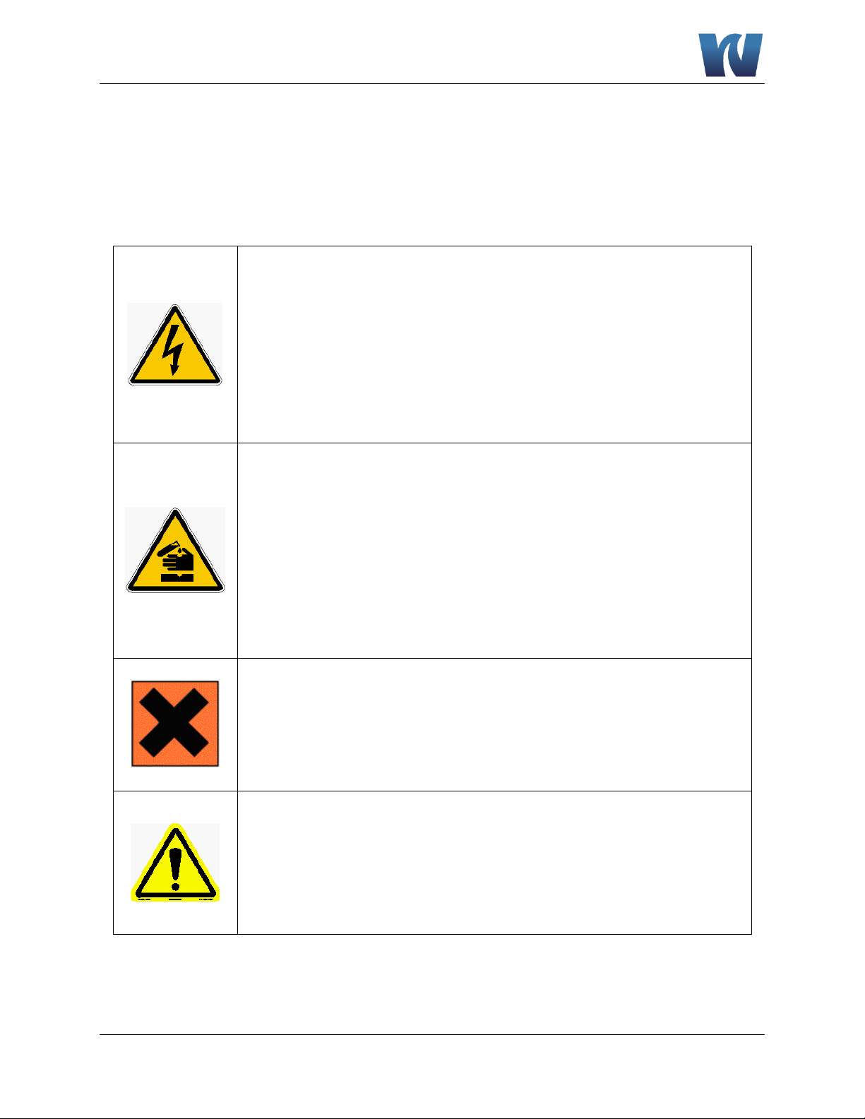
1.2.2 List of Warnings and Potential Dangers................................................................................ 9
1.2.3 Sample................................................................................................................................. 10
1.2.4 Analyzer General Hazards ................................................................................................... 10
2Introduction................................................................................................11
2.1 Preliminary Remarks ...................................................................................................................11
2.2 Working Principle........................................................................................................................ 11
2.3 Flow & Component Diagram....................................................................................................... 13
2.4 Wet-Section ................................................................................................................................ 14
2.5 Electronics...................................................................................................................................14
3Installation .................................................................................................15
3.1 Receiving .....................................................................................................................................15
3.2 Analyzer Handling .......................................................................................................................15
3.3 Location and Mounting...............................................................................................................15
3.4 Mounting Schematics .................................................................................................................16
3.5 Sample Connections....................................................................................................................17
3.6 Electrical Connections................................................................................................................. 18
3.6.1 Transmitter Enclosure......................................................................................................... 19
3.6.2 Terminal Block Connections................................................................................................ 20
3.6.3 AC Power Connection .........................................................................................................21
3.6.4 User Signal Connections...................................................................................................... 22
4Analyzer Initial Start-Up..............................................................................23
4.1 Preparing the Analyzer for Start-Up ...........................................................................................23
4.1.1 Installing Cation Resin Bottle ..............................................................................................23
4.1.2 Installing Decarbonization Column .....................................................................................25
4.2 Putting the Analyzer Online ........................................................................................................ 25