NDS ZeroWire Mobile User manual

ZeroWire Mobile®
USER MANUAL
U.S. ONLY - ENGLISH


© 2020 NDS Surgical Imaging, LLC. All rights reserved.
Information in this document has been carefully checked for accuracy; however, no guarantee is given to the
correctness of the contents. This document is subject to change without notice. NDS provides this information as
reference only. Reference to products from other vendors does not imply any recommendation or endorsement.
This document contains proprietary information protected by copyright. No part of this manual may be
reproduced by any mechanical, electronic, or other means, in any form, without prior written permission of NDS.
All trademarks are the property of their respective owners.


Table of Contents
Safety Information . . . . . . . . . . . . . . . . . . . . . . . . . . . . . . . . . . . . . . . . . . . . . . . . . . . . . . . . . . . . . . . . . . . . . . . . . . . . . . . . . . 1
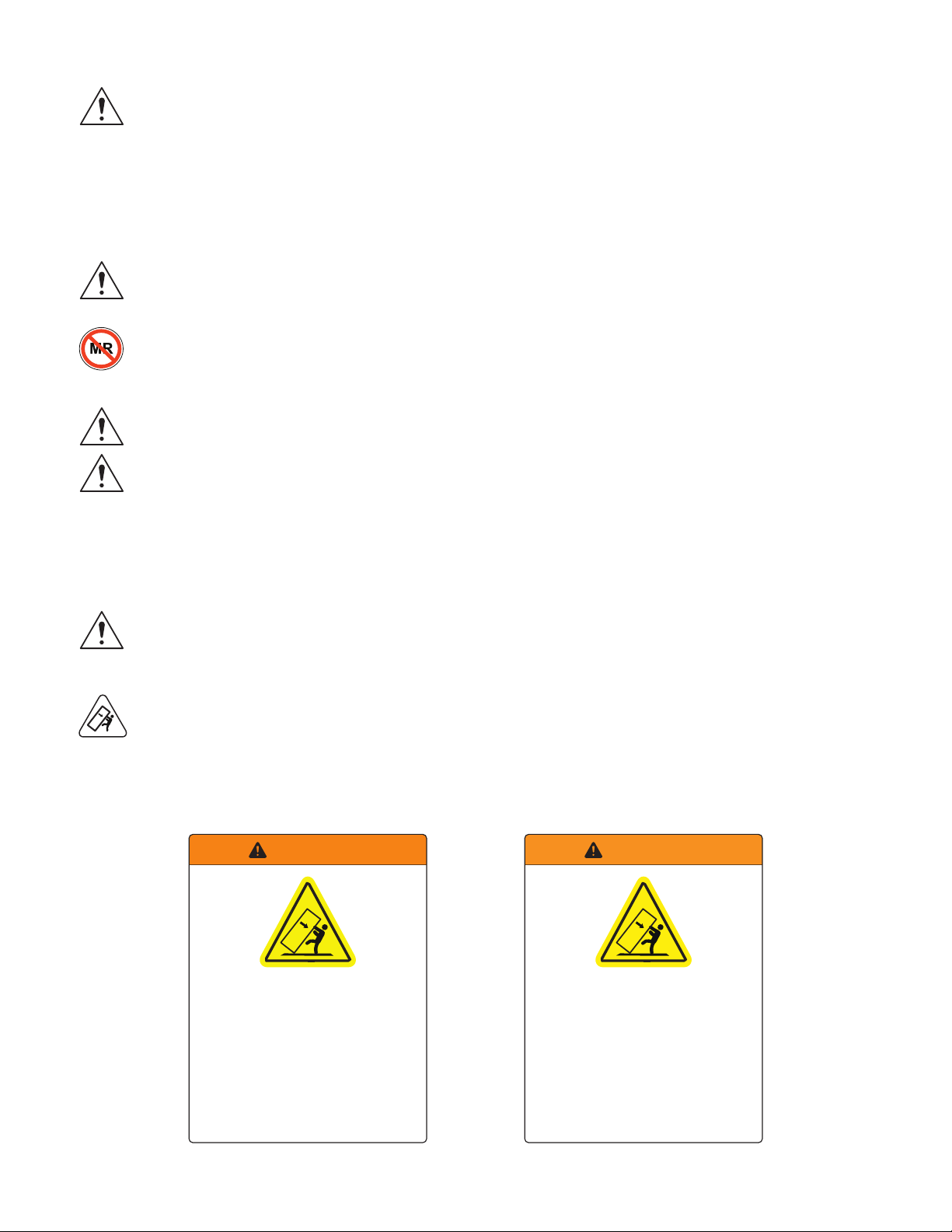
Warnings and Cautions . . . . . . . . . . . . . . . . . . . . . . . . . . . . . . . . . . . . . . . . . . . . . . . . . . . . . . . . . . . . . . . . . . . . . . . . . . . 1
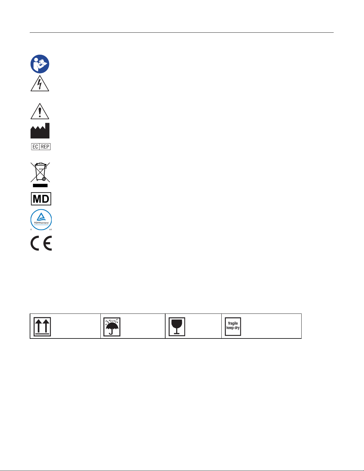
Shipping Symbols . . . . . . . . . . . . . . . . . . . . . . . . . . . . . . . . . . . . . . . . . . . . . . . . . . . . . . . . . . . . . . . . . . . . . . . . . . . . . . . . 1
Power Module Safety Symbols . . . . . . . . . . . . . . . . . . . . . . . . . . . . . . . . . . . . . . . . . . . . . . . . . . . . . . . . . . . . . . . . . . . . 2
Warning Notices . . . . . . . . . . . . . . . . . . . . . . . . . . . . . . . . . . . . . . . . . . . . . . . . . . . . . . . . . . . . . . . . . . . . . . . . . . . . . . . . . . 3
Intended Use and Contraindications. . . . . . . . . . . . . . . . . . . . . . . . . . . . . . . . . . . . . . . . . . . . . . . . . . . . . . . . . . . . . . . 4
Recycling. . . . . . . . . . . . . . . . . . . . . . . . . . . . . . . . . . . . . . . . . . . . . . . . . . . . . . . . . . . . . . . . . . . . . . . . . . . . . . . . . . . . . . . . . 4
General Specifications . . . . . . . . . . . . . . . . . . . . . . . . . . . . . . . . . . . . . . . . . . . . . . . . . . . . . . . . . . . . . . . . . . . . . . . . . . . . . . 5
ZeroWire Mobile. . . . . . . . . . . . . . . . . . . . . . . . . . . . . . . . . . . . . . . . . . . . . . . . . . . . . . . . . . . . . . . . . . . . . . . . . . . . . . . . . . 5
ZeroWire Mobile Accessories. . . . . . . . . . . . . . . . . . . . . . . . . . . . . . . . . . . . . . . . . . . . . . . . . . . . . . . . . . . . . . . . . . . . . . 5
Safety Features . . . . . . . . . . . . . . . . . . . . . . . . . . . . . . . . . . . . . . . . . . . . . . . . . . . . . . . . . . . . . . . . . . . . . . . . . . . . . . . . . . . 5
Power Requirements. . . . . . . . . . . . . . . . . . . . . . . . . . . . . . . . . . . . . . . . . . . . . . . . . . . . . . . . . . . . . . . . . . . . . . . . . . . . . . 6
Power Module Requirements . . . . . . . . . . . . . . . . . . . . . . . . . . . . . . . . . . . . . . . . . . . . . . . . . . . . . . . . . . . . . . . . . . . . . 6
Environmental Requirements . . . . . . . . . . . . . . . . . . . . . . . . . . . . . . . . . . . . . . . . . . . . . . . . . . . . . . . . . . . . . . . . . . . . . 7
ZeroWire Mobile Assembly. . . . . . . . . . . . . . . . . . . . . . . . . . . . . . . . . . . . . . . . . . . . . . . . . . . . . . . . . . . . . . . . . . . . . . . . . . 9
Assembly Procedure . . . . . . . . . . . . . . . . . . . . . . . . . . . . . . . . . . . . . . . . . . . . . . . . . . . . . . . . . . . . . . . . . . . . . . . . . . . . . . 9
Field Replaceable Parts . . . . . . . . . . . . . . . . . . . . . . . . . . . . . . . . . . . . . . . . . . . . . . . . . . . . . . . . . . . . . . . . . . . . . . . . . . 10
Charging Station Installation . . . . . . . . . . . . . . . . . . . . . . . . . . . . . . . . . . . . . . . . . . . . . . . . . . . . . . . . . . . . . . . . . . . . . . . 11
Wall Mounting Procedure . . . . . . . . . . . . . . . . . . . . . . . . . . . . . . . . . . . . . . . . . . . . . . . . . . . . . . . . . . . . . . . . . . . . . . . . 11
Maintenance . . . . . . . . . . . . . . . . . . . . . . . . . . . . . . . . . . . . . . . . . . . . . . . . . . . . . . . . . . . . . . . . . . . . . . . . . . . . . . . . . . . . . . . 12
Servicing . . . . . . . . . . . . . . . . . . . . . . . . . . . . . . . . . . . . . . . . . . . . . . . . . . . . . . . . . . . . . . . . . . . . . . . . . . . . . . . . . . . . . . . . 12
General Precautions . . . . . . . . . . . . . . . . . . . . . . . . . . . . . . . . . . . . . . . . . . . . . . . . . . . . . . . . . . . . . . . . . . . . . . . . . . . . . 12
Cleaning . . . . . . . . . . . . . . . . . . . . . . . . . . . . . . . . . . . . . . . . . . . . . . . . . . . . . . . . . . . . . . . . . . . . . . . . . . . . . . . . . . . . . . . . 12
ZeroWire Mobile Components . . . . . . . . . . . . . . . . . . . . . . . . . . . . . . . . . . . . . . . . . . . . . . . . . . . . . . . . . . . . . . . . . . . . . 13
Optional Components . . . . . . . . . . . . . . . . . . . . . . . . . . . . . . . . . . . . . . . . . . . . . . . . . . . . . . . . . . . . . . . . . . . . . . . . . . . 13
ZeroWire Mobile Monitor Installation . . . . . . . . . . . . . . . . . . . . . . . . . . . . . . . . . . . . . . . . . . . . . . . . . . . . . . . . . . . . . . 14
Mounting a Monitor to the ZeroWire Mobile. . . . . . . . . . . . . . . . . . . . . . . . . . . . . . . . . . . . . . . . . . . . . . . . . . . . . . 14
Connecting a Monitor to the ZeroWire Mobile . . . . . . . . . . . . . . . . . . . . . . . . . . . . . . . . . . . . . . . . . . . . . . . . . . . . 14
ZeroWire Mobile Monitor Setup . . . . . . . . . . . . . . . . . . . . . . . . . . . . . . . . . . . . . . . . . . . . . . . . . . . . . . . . . . . . . . . . . . . . 15
Height Adjustment of Monitor . . . . . . . . . . . . . . . . . . . . . . . . . . . . . . . . . . . . . . . . . . . . . . . . . . . . . . . . . . . . . . . . . . . 15
Tilt Adjustment of Monitor . . . . . . . . . . . . . . . . . . . . . . . . . . . . . . . . . . . . . . . . . . . . . . . . . . . . . . . . . . . . . . . . . . . . . . . 15
ZeroWire Mobile Transport. . . . . . . . . . . . . . . . . . . . . . . . . . . . . . . . . . . . . . . . . . . . . . . . . . . . . . . . . . . . . . . . . . . . . . . . . 16
Procedure for Moving the ZeroWire Mobile. . . . . . . . . . . . . . . . . . . . . . . . . . . . . . . . . . . . . . . . . . . . . . . . . . . . . . . 16
Charging Station . . . . . . . . . . . . . . . . . . . . . . . . . . . . . . . . . . . . . . . . . . . . . . . . . . . . . . . . . . . . . . . . . . . . . . . . . . . . . . . . . . . 17
Charging Station Overview. . . . . . . . . . . . . . . . . . . . . . . . . . . . . . . . . . . . . . . . . . . . . . . . . . . . . . . . . . . . . . . . . . . . . . . 17
Power Modules . . . . . . . . . . . . . . . . . . . . . . . . . . . . . . . . . . . . . . . . . . . . . . . . . . . . . . . . . . . . . . . . . . . . . . . . . . . . . . . . . . . . 18
Preparing a Power Module for First Use. . . . . . . . . . . . . . . . . . . . . . . . . . . . . . . . . . . . . . . . . . . . . . . . . . . . . . . . . . . 18
Power Module Overview . . . . . . . . . . . . . . . . . . . . . . . . . . . . . . . . . . . . . . . . . . . . . . . . . . . . . . . . . . . . . . . . . . . . . . . . . 18
Power Module Charging . . . . . . . . . . . . . . . . . . . . . . . . . . . . . . . . . . . . . . . . . . . . . . . . . . . . . . . . . . . . . . . . . . . . . . . . . 19
Power Module Docking . . . . . . . . . . . . . . . . . . . . . . . . . . . . . . . . . . . . . . . . . . . . . . . . . . . . . . . . . . . . . . . . . . . . . . . . . . 21
Power Module Undocking . . . . . . . . . . . . . . . . . . . . . . . . . . . . . . . . . . . . . . . . . . . . . . . . . . . . . . . . . . . . . . . . . . . . . . . 21
External Charger . . . . . . . . . . . . . . . . . . . . . . . . . . . . . . . . . . . . . . . . . . . . . . . . . . . . . . . . . . . . . . . . . . . . . . . . . . . . . . . . . . . 22
Electromagnetic Compatibility Tables. . . . . . . . . . . . . . . . . . . . . . . . . . . . . . . . . . . . . . . . . . . . . . . . . . . . . . . . . . . . . . 25
Electromagnetic Immunity . . . . . . . . . . . . . . . . . . . . . . . . . . . . . . . . . . . . . . . . . . . . . . . . . . . . . . . . . . . . . . . . . . . . . . . 26
Recommended Separation Distances. . . . . . . . . . . . . . . . . . . . . . . . . . . . . . . . . . . . . . . . . . . . . . . . . . . . . . . . . . . . . 27
Terms and Conditions . . . . . . . . . . . . . . . . . . . . . . . . . . . . . . . . . . . . . . . . . . . . . . . . . . . . . . . . . . . . . . . . . . . . . . . . . . . . . . 29
Declarations of Conformity. . . . . . . . . . . . . . . . . . . . . . . . . . . . . . . . . . . . . . . . . . . . . . . . . . . . . . . . . . . . . . . . . . . . . . . 29
Legal Statement . . . . . . . . . . . . . . . . . . . . . . . . . . . . . . . . . . . . . . . . . . . . . . . . . . . . . . . . . . . . . . . . . . . . . . . . . . . . . . . . . 30


Safety Information | 1
Safety Information
Warnings and Cautions
This symbol alerts the user that important information regarding the installation and/or operation of
this equipment follows. Information preceded by this symbol should be read carefully.
This symbol warns the user that un-insulated voltage within the unit may have sufficient magnitude to
cause electrical shock. Do not touch any part inside the unit.
Note: There are no user serviceable parts inside. Refer servicing to qualified service personnel.
This symbol alerts the user that information preceded by this symbol should be read carefully to avoid
damage to the equipment.
This symbol denotes the manufacturer.
This symbol denotes the manufacturer’s European Community representative.
This symbol indicates compliance with the Waste Electrical and Electronic Equipment Directive (WEEE
Directive).
This symbol indicates the device is a Medical Device. This product is intended only for use by
healthcare professionals in professional healthcare environments.
Safety Compliance
This product is T.U.V. approved with respect to electric shock, fire and mechanical hazards only in
accordance with CAN/CSA C22.2 No. 60601-1 and ANSI/AAMI ES60601-1.
Safety Compliance
This product meets the requirements of EN60601-1 so as to conform to the 2017/745 Medical Device
Regulation of European Union.
Note: Any serious incident or adverse event that has occurred in relation to the device should be reported to the
manufacturer and the competent authority of the Member State in which the user and/or patient is established.
Shipping Symbols
Shipping symbols, as defined below are printed on the shipping containers used to transport this product.
Position the
container up
Keep dry Fragile Fragile keep dry

2 | Safety Information
Power Module Safety Symbols
This product complies to the above standards.
This product is intended only for use by healthcare professionals in professional healthcare environments.
This product is a Class II medical device. No modifications are allowed.
This product is intended for continuous operation.
Federal law restricts this deviceto sale by oron the order of a medical practitioner.
Read instructions
for use before
using or installing
the product.
Conformité
Européenne
Care should be
taken when using
the product.
Waste Electrical and
Electronic Equipment
Directive (EU)
Recyclable (Taiwan) Conforms to the
transportation
standards for Class 9
hazardous materials.
Federal
Communications
Commission
Conformance (US)
Underwriters
Laboratory (UL)
listed
component.
Meets the
requirements of
the current EU
RoHS Directive
2011/65/EU.
Lithium Ion
Recycling (Japan)
Includes Universal
Recycling symbol.
Keep out of
sunlight
Do not use if
housing is cracked
or broken.
Operating
temperature
range

Safety Information | 3
Warning Notices
As with any power system that stores high levels of energy, there is always the risk of leakage, fire or
explosion. Although adequate provision has been taken in the design and testing of this product to
make it completely safe, it is the user’s responsibility to ensure that they are completely familiar with
these instructions for use, and that they have received appropriate safety instructions on safe handling of the
power modules and the use of the system generally.
Regular maintenance is required to ensure that the power modules and electrical systems are free from wear and
tear, or any damage whatsoever. Seek advice if in any doubt, and remove any damaged power modules
immediately from use.
Warning: The ZeroWire Mobile is designed only for supporting secondary displays, and the device is not
intended for use with life supporting equipment, and under no circumstance is it permitted to be used
with such equipment.
Warning: Do not use in Magnetic Resonance (MR) environments.
Emergency Warning
Caution: Power modules used in this device may present a risk of fire or chemical burn if mistreated. Do
not disassemble, heat above 45°C, or incinerate.
In extremely rare case of smoke, fire, or partial material decomposition of a power module, if safe to do
so, submerse the unit fully in water. Call the fire department.
Low Charge Level Audible Notification
A beep is repeated at 2-minute intervals starting 30 minutes prior to full discharge of a secondary power module
if the depleted primary power module has not been replaced with a charged unit.
Note: The Low Charge Level Notification is functionally critical and cannot be disabled.
Warning: The ZeroWire Mobile should not be used with medical equipment that poses a safety risk to
patients if battery power is lost, or the audible notification is not recognized.
Tipping Hazard
Warning: ZeroWire Mobile is designed for deployment on horizontal surfaces. The device is not intended
to be left unattended on sloping or uneven surfaces. For instructions on safe transport of the ZeroWire
Mobile, see “Procedure for Moving the ZeroWire Mobile” on page 16.
Tipping Hazard Warning Labels
Placed on Base Column of ZeroWire Mobile.
English Warning Label French Warning Label
WARNING
Tipping Hazard
To avoid potential injury, do not lean against
the stand or push the stand while a caster is
locked. Before attempting to move the stand,
lower the display to the lowest position and
unlock all casters. Securely grasp the stand
with both hands during transport. Reference
the user manual for more information.
Do not remove – permanent warning notice.
WARNING
Risque de basculement
Pour éviter les risques de blessures, ne pas
pencher contre le support ou pousser le
support quand une des roues est verrouillée.
Avant d'essayer de déplacer le support,
abaisser l'écran à la position la plus basse et
déverrouiller toutes les roues. Tenir
fermement le support avec les deux mains
pendant le transport. Référence au mode
d'emploi pour plus d' information.
Ne pas enlever – avertissement permanent.

4 | Safety Information
Power Module Notification
Do not allow any power module to sit unused for more than three (3) months with a limited charge of 30% or less
(three LED bars). Regular use of the power modules are recommended to maintain optimum performance. If the
power module does not turn on when placed onto a 4-dock ZeroWire Mobile Charging Station for at least three
days continuously, contact NDS Customer Service.
Intended Use and Contraindications
Intended Use
The ZeroWire Mobile, Radiance Ultra series ZeroWire Embedded, and ZeroWire G2 are a paired video
communication transmitter and receiver, intended for delivery of medical video signals from a source such as an
endoscopy camera/processor, or other video source over a radio-frequency link to a video for review and analysis
of medical images during endoscopic and general surgical procedures.
The ZeroWire Mobile, Radiance Ultra series, and ZeroWire G2 wireless video systems are non-sterile reusable
devices not intended for use in the sterile field.
Contraindications
The ZeroWire Mobile is not intended for use with life supporting equipment, and under no circumstance must it
be used in this way. Any use or integration with a medical device is strictly and exclusively the responsibility of
the Medical Device manufacturer, agent, reseller or integrator selling this product. They are responsible for
appropriate integrated system’s product safety, EMC, regulatory, risk management and product testing for their
intended use.
1. Do not use this product in the presence of flammable anesthetics mixture with air, oxygen or nitrous oxide.
2. No part of this product may come in contact with a patient. Never touch the product and a patient at the
same time.
3. For mission critical applications, we strongly recommend that a replacement unit be immediately available.
Recycling
Power modules contain Lithium Ion batteries. Follow local governing ordinances and recycling plans
regarding the recycling or disposal of this equipment.
• Do not disassemble, puncture or incinerate the power modules or batteries.
• Dispose of used power modules promptly.
• Keep away from children.
• Do not dispose of in fire.

General Specifications | 5
General Specifications
The ZeroWire Mobile is designed to provide power to an electrical load and can be used continuously.
Note: Specifications are subject to change without notice. Contact factory for current specifications.
ZeroWire Mobile
The ZeroWire Mobile includes the following:
• ZeroWire Mobile stand with 125 mm diameter casters (5x)
• Rear-mounted fixed-position handle on the base column
• Extension column provides monitor height adjustment, and the VESA hinged mount provides monitor tilt
adjustment (see“ZeroWire Mobile Monitor Setup” on page 15)
ZeroWire Mobile Accessories
ZeroWire Mobile accessories include the following:
• ZeroWire Mobile power modules including built-in regulation (output 24 Vdc, maximum 150 W/6.25 A
continuous operation).
• ZeroWire Mobile wall-mounted Charging Station (4-bay charger; input 100–240 Vac, 4.6–2.3 A, 50/60 Hz), with
two hospital-grade AC power cords (NEMA 5-15p for North America and CEE 7/7 for EMEA).
• ZeroWire Mobile power cable for NDS 19" – 26" monitors.
• ZeroWire Mobile power cable for NDS 26" HB – 32" monitors.
• 4-bay charger service kit (part number: 90Z0176)
Please reference “ZeroWire Mobile Components” on page 13 for additional information regarding ZeroWire
Mobile system components and accessories.
Safety Features
See “Charging Station Overview” on page 17, and “Power Module Overview” on page 18.
Authentication
All ZeroWire Mobile power modules are factory programmed with a password code used for verification that the
power module is a genuine NDS product each time the unit is docked, preventing use of counterfeit devices.
ZeroWire Mobile is a medical device, therefore, power module authentication is a critical safety technology to
protect both the user and the patient.
Dock Detection
External contacts of power modules are enabled only when docked. When power modules are undocked, the
dock detection feature isolates internal cell voltage from the external contacts for protection against electric
shock and short circuit hazards.
Temperature Monitoring
The internal temperature of docked power modules is continuously monitored. If the internal temperature
exceeds the safe operating temperature range, charging or discharging is suspended until the temperature is
restored to a safe level. See “Operation” on page 7.
Overcharge Prevention
Charging is automatically terminated when power modules are fully charged.

6 | General Specifications
Power Requirements
Power Cord for Wall-Mounted Charging Station
Two hospital-grade AC power cords are provided with the Charging Station, enabling use of the correct plug for
your power source.
• Use of non-NDS AC power cords can void the Warranty.
• Disconnect the power cord from the AC mains. The power cord is the only recognized disconnect device.
• MEDICAL EQUIPMENT should be positioned so that the disconnect device is readily accessible.
• When used in the U.S. at voltages over 120 volts, the Charging Station must be powered from a center-tapped
circuit.
• The Charging Station must be installed in a location with easy access to the AC mains power source.
Power Modules for ZeroWire Mobile Stand
Use only NDS power modules.
• To power off the ZeroWire Mobile stand, remove both power modules from the stand docks.
• The ZeroWire Mobile stand must be positioned in a location with easy access to the stand docks.
Power Module Requirements
The capacity of a fully charged power module is 10 Ah. A power module at 10% or 1 Ah capacity is considered to
be fully discharged, with a marginal charge needed to maintain system functionality.
Power modules not in active use self-discharge at an average rate of < 1 mA/hour.
Operation
First Use Charge Requirement
Prior to first use after storage or transportation, power modules must be charged to full capacity to set an
internal benchmark used to calculate percentages of capacity for accurate display of charge levels during use.
Active Use Charge Requirement
At least once every 30 days, power modules in active use must be fully charged from a discharged state to
maintain accurate display of charge levels and to maximize life of the unit. This is typically accomplished in the
process of normal usage.
Power Module Storage
Power modules to be placed in long-term storage should be charged initially to at least an 80% level to provide a
5 Ah buffer charge, from which self-discharge would take approximately 4000 hours (166 days or 5.5 months) to
reach the fully discharged 10% level.
Check on charge levels beginning at around 40 days after being placed in storage, and charge back to at least
80% when levels have dropped to 30%. It is important to maintain a charge level above 10% to prevent
discharge cut-off (see “Discharge Cut-Off” on page 20).
Shipping
Prior to shipping, power modules should have a limited charge of 30% or less (three LED bars).
Warning: Power modules contain Lithium, and are classified as Class 9 Dangerous Goods for
transportation, requiring that all national and international regulations be observed. Check with your
local transport representative for advice on shipping in your region. For information regarding return of
damaged or faulty power modules, contact NDS Customer Service.

General Specifications | 7
Environmental Requirements
Operation
The operating temperature range for the ZeroWire Mobile should not exceed 32° – 104°F (0° – 40°C). Do not use
outside of this temperature range.
• To protect the safety of the battery cells, power modules may stop charging if the internal temperature is
above this specific range.
• Operating relative humidity range for the ZeroWire Mobile should not exceed 20% – 75% (non-condensing).
• Operating altitude range for the ZeroWire Mobile should not exceed 0 - 6562 ft (0 – 2000 m), with a pressure
range not to exceed 14.65 - 11.75 PSI (101 – 81 kPa).
Failure to observe these conditions will invalidate the warranty and reduce the life expectancy of power
modules.
Storage
• Storage temperature range for the ZeroWire Mobile should not exceed 14° -113° F (-10° – 45°C).
• Storage relative humidity range for the ZeroWire Mobile should not exceed 30% – 80% (non-condensing).
Failure to observe these conditions will invalidate the warranty and reduce the life expectancy of power
modules.
Shipping
It is recommended to retain original boxes and packing materials for use when shipping.
• Shipping temperature range for the ZeroWire Mobile should not exceed 14 ° - 113° F (-10° – 45°C).
• Shipping relative humidity range for the ZeroWire Mobile should not exceed 30% – 80% (non-condensing).
Failure to observe these conditions will invalidate the warranty and reduce the life expectancy of power
modules.

8 | General Specifications

ZeroWire Mobile Assembly | 9
ZeroWire Mobile Assembly
Components of the ZeroWire Mobile stand
included in your shipment:
Assembly Procedure
1. Attach Casters (13) to underside of Base (12)
with M12x65mm Cap Head Screws (14) using
10 mm Allen Key, torqued to 131 lb·in (14.8
N·m). Suggested placement of ESD caster at
rear leg location.
2. Attach Base to Outer Extrusion Subassembly
(4) with M6x35mm Cap Head Screws (18) and
Flat Washers (19) using 5 mm Allen Key,
torqued to 28.4 lb·in (3.2 N·m).
3. Attach Base Cover (17) to Base with
M6x12mm Button Head Screws (15) and M6
Split Washers (16) using 4 mm Allen Key,
torqued to 28.4 lb·in (3.2 N·m).
4. Attach Handle Subassembly (10) to the Channel Adapter (9) on the Outer Extrusion Subassembly with
M6x12mm CSK Head Screws (11) using 4 mm Allen Key, torqued to 13.5 lb·in (1.5 N·m).
5. Attach Hinged Mounting Plate (1) to the Top Plate (2) of the Inner Extrusion Subassembly (3) with M6x16mm
Cap Head Screws (5) and M6 Flat Washers (6) using 4 mm Allen Key, torqued to 28.4 lb·in (3.2 N·m).
6. Attach Release Lever (7) to the Inner Extrusion Subassembly by screwing the threaded end of the Release
Lever into the Release Lever Subassembly (8), and securely hand-tighten.
1Hinged Mounting Plate
2Top Plate
3Inner Extrusion Subassembly
4Outer Extrusion Subassembly
5M6x16mm Cap Head Screw (2x)
6M6 Flat Washer (2x)
7Release Lever
8Release Lever Subassembly
9Channel Adapter
10 Handle Subassembly
11 M6x12mm Flat Hd SOC Screw (2x)
12 Base
13 Casters
Brake Caster (4x)
Electric Conductive (ESD) Caster (1x)
14 M12x65mm Cap Head Screw (5x)
15 M6x12mm Button Head Screw (4x)
16 M6 Star Washer Ext Tooth (4x)
17 Base Cover
18 M6x35mm Cap Head Screw (4x)
19 M6 Flat Washer (4x)
USENDS
POWER
MODULE
ONLY
PN:30D0001
MEDICALDEVICE
SERIAL# MODEL# PART#
T.408.776.0085(USA)
www.ndssi.com
NDS
WARNING
TIPPINGHAZARD
Toavoidpotentialinjury, do not lean against the
standor push the stand while a casteris locked.
Beforeattempting to move the stand,lower the
displayto the lowestposition and unlock all
casters.Securely graspt
he stand with b
oth
handsduringtransport.
Referencetheuser manualfor more information.
DONOTREMOVE –PERMANENT WARNING NOTICE!
PUSH
BUTTON TO
RELEASE
19
18
17161515
14
13
12
11
10
9
8
7
6
5
4
3
2
1

10 | ZeroWire Mobile Assembly
Field Replaceable Parts
Use only NDS approved power modules and replacement parts, certified for use with the ZeroWire Mobile
system. Failure to comply will invalidate your warranty and may present serious dangers.
For service, warranty replacement, or purchase of any items in the following list, contact NDS at:
Part
Number Description
90Z0164 ZeroWire Mobile Service Kit, Castor
90Z0292 ZeroWire Mobile Service Kit, Castor, Electric
Conductive
90Z0165 ZeroWire Mobile Service Kit, Handle Assembly
90Z0166 ZeroWire Mobile Service Kit, Covers
90Z0168 ZeroWire Mobile, Neutrik Power Cable
90Z0169 ZeroWire Mobile, Switchcraft Power Cable
90Z0170 ZeroWire Mobile Service Kit, Connector Cap
90Z0171 ZeroWire Mobile Service Kit, Lever Assembly
90Z0172 ZeroWire Mobile Service Kit, VESA Mount Assembly
90Z0176 ZeroWire Mobile Service Kit, 4-Bay Charger Wall
Mount Bracket Assembly
30H0006 External Charger

Charging Station Installation | 11
Charging Station Installation
Wall Mounting Procedure
Warning: Installation of the Charging Station Wall Mount Bracket (90Z0176) must be performed by a
skilled professional. The wall mount installation must secure weight loads ranging from 27 lbs (12.12 kg)
to 34 lbs (15.42 kg) as shown below.
1. Determine an appropriate wall location with unobstructed access to a grounded AC mains power outlet that
is clear of obstacles to regular foot traffic required to move power modules to and from the charging station
and ZeroWire Mobile Stand(s).
2. Determine location of wall studs on which the wall mount bracket will be attached, and determine an
ergonomic height for the charging station installation.
3. When the Wall Mount Bracket has been securely installed to the wall location, position the Bracket Tab Slots
on the back of the Charging Station over the Bracket Tabs of the Wall Mount Bracket and carefully lower the
Charging Station until both Slots are securely mounted on the Tabs.
4. Connect the Charging Station to AC mains using the provided hospital grade AC mains Power Cable (P/N
35D0022-B). Illuminated LEDs below each charging bay indicate that the Charging Station is powered on.
Charging Station 19.0 lb. 8,62 kg
Power Module 3.5 lb. 1,59 kg
Wall Mount Bracket 1.0 lb. 0,45 kg
2 Modules Total Weight: 27.0 lb. 12,25 kg
4 Modules Total Weight: 34.0 lb. 15,42 kg
30.25" (768.35 mm)
18" (457.2 mm)
18" (457.2 mm)
20.875" (530.225 mm)
3.55"
(90.17 mm)
2.0" (50.8 mm) 2.0" (50.8 mm)
Wall Mount Bracket Front View
6.125"
(155.575mm) 6.125"
(155.575mm)
3.625"
(92.075 mm)
14.5"
(368.3 mm)
18.125"
(460.375 mm)
Charging Station Back View
Bracket
Tab
Slot (2x)
Bracket
Tab (2x)
Cushion
Pad (6x)

12 | Maintenance
Maintenance
Servicing
No maintenance should be performed while the equipment is in use.
If a power module or any part of the electrical system has been damaged or compromised in anyway, remove
from use immediately and do not use.
Warning: The ZeroWire Mobile charging station and power modules have no user serviceable parts. Do
not disassemble or modify the charging station and power modules in any way.
Warning: Use of non-NDS power modules will render the unit inoperable. Use of non-NDS power
modules may present a risk of fire or explosion.
General Precautions
• Before use, confirm that both power modules are fully charged and correctly docked.
• Do not use or store any part of the ZeroWire Mobile system, including power modules and charger in a
location exposed to direct sunlight or sources of direct heat such as fire or a heater.
• Power modules can only be charged using approved NDS ZeroWire Mobile Chargers.
• Do not submerge power modules in water or any fluid.
• Do not strike, throw, drop, or subject power modules to physical shock.
• Do not pierce casing of power modules with nails or other sharp objects.
• Do not attempt to open the power module enclosure.
• Do not stand on a power module.
Note: It is recommended that power modules be regularly inspected for enclosure damage. If a unit is damaged,
it should be immediately removed from use.
Cleaning
The ZeroWire Mobile system should be kept clean and free of dust. The Dock, charger and Power Module should
be cleaned using a damp cloth with water or alcohol solution. Please observe the follow precautions.
Power modules are protected by an impermeable watertight enclosure, allowing the units to be safely cleaned
by using a dampened cloth.
Please observe the follow precautions:
• Turn the system off and disconnect from the AC power supply before cleaning
• Do not pour fluid over any part of the system.
• Do not allow fluids to penetrate the exterior surface of the dock module(s)
• Do not use abrasive cleaners or strong solvents such as acetone or acetone-based compounds.
Warning: Prior to cleaning, units should be turned OFF and disconnected from power sources.
• Do not use abrasive cleaners or strong solvents such as acetone or acetone-based compounds.
Warning: Do not pour fluids over any part of the ZeroWire Mobile Stand.
• Do not allow fluids to penetrate the exterior surface of the dock modules, as severe damage to the unit
can result.
In the event of fluid penetration, use a dry cloth to remove fluid from all external surfaces, and allow the unit to
dry thoroughly. Consult a qualified technician before attempting further use.

ZeroWire Mobile Components | 13
ZeroWire Mobile Components
The ZeroWire Mobile base system includes the following standard
components:
• ZeroWire Mobile Stand (P/N 90Z0161)
Optional Components
•ExternalCharger(P/N
30H0006) for use with the
ZeroWire Mobile.
• Power Cable (P/N 90Z0168)
for use with NDS 26" HB–32"
monitors (Neutrik connector)
• Power Cable (P/N 90Z0169)
for use with NDS 19”–26”
monitors (SwitchCraft
connector)
• ZeroWire Mobile wall power module charger, 4-bay (P/N: 30H0001)with
one each United States and European power cord
• ZeroWire Mobile power
module (P/N 30H0006)

14 | ZeroWire Mobile Monitor Installation
ZeroWire Mobile Monitor Installation
Mounting a Monitor to the ZeroWire Mobile
1. Tilt the mounting plate back to a horizontal position.
2. Place the monitor on the mounting plate and align the monitor’s VESA 100 x 100 mm hole mount pattern to
the corresponding hinged mounting plate screw holes. Attach the monitor using the provided M4 thumb
screws. Lightly tighten each screw until all 4 screws have been installed, and then tighten each screw securely.
Connecting a Monitor to the ZeroWire Mobile
1. Remove the monitor cable cover.
2. Connect the monitor DC power cable first to the ZeroWire Mobile DC output connector, and then to the
monitor DC input connector, with the power cable passing between the release lever and monitor.
Note: The capped port is reserved for future use.
3. Reinstall the monitor cable cover.
Other manuals for ZeroWire Mobile
1
This manual suits for next models
10
Table of contents
Other NDS Medical Equipment manuals

NDS
NDS Radiance Ultra User manual

NDS
NDS ZeroWire Mobile User manual

NDS
NDS RADIANCE G2 User manual

NDS
NDS ExpandOR User manual

NDS
NDS EndoVue Plus 15" User manual

NDS
NDS EndoVue Plus 15" User manual

NDS
NDS RADIANCE G2 User manual

NDS
NDS ExpandOR User manual

NDS
NDS ConductOR User manual

NDS
NDS 90R0123 User manual