NDS Radiance Ultra User manual

Radiance® Ultra
with optional ZeroWire Embedded Wireless Technology
USER MANUAL
ENGLISH

en © 2021 NDS Surgical Imaging, LLC. All rights reserved.
Information in this document has been carefully checked for accuracy; however, no guarantee is given to the cor-
rectness of the contents. This document is subject to change without notice. NDS provides this information as refer-
ence only. Reference to products from other vendors does not imply any recommendation or endorsement.
This document contains proprietary information protected by copyright. No part of this manual may be reproduced
by any mechanical, electronic, or other means, in any form, without prior written permission of NDS.
All trademarks are the property of their respective owners.

Symbols
Symbols
Follow instructions for
use (white image on a
blue background)
Consult instructions for
use
Instructions for use and
translated copies are
published on the NDS
website at:
www.ndssi.com/user-
manuals/
General warning
Warning; Electricity
Authorized Representat-
ive in the European
Community
Medical Device
Authorized for Sale or
use by Physician only
Caution
Manufacturer
Date of manufacture
(YYYY-MM-DD)
Catalogue number
Serial number
Batch code
Atmospheric pressure
limitation
Humidity limitation
Temperature limit
Waste management
Fragile
Keep dry
This way up
Complies to IEC 60601-1
including US and Cana-
dian deviations in their
respective valid version
The Canadian Standards
Association (CSA) certi-
fication mark represents
safety approval by Cana-
dian Standards Associ-
ation for Canada and the
United States.
EurAsian Conformity
(EAC) mark represents
safety approval by Cus-
tom Union countries:
Belarus, Russia, Kazakh-
stan, Armenia, Kyrgyz-
stan.

China Compulsory Certi-
ficate (CCC) mark for In-
formation Technology
Equipment (ITE)
products.
United States Federal
Communications Com-
mission (FCC) symbol in-
dicates EMC compliance
per FCC standards.
No hazardous sub-
stances contained in the
device
Contains restricted sub-
stances. The symbol
number refers in years
to the Environmental
Protection Use Period
(EPUP), during which the
product can be safely
used, and following
which should be imme-
diately recycled.
Equipotentiality
Closed (On) Switch.
Open (Off) Switch.
Protective earth; pro-
tective ground
Alternating current
Non-ionizing electro-
magnetic radiation
Symbols
en

Table of Contents
1 Safety Information ..................................................................................................................................... 7
1.1 Warnings and Cautions................................................................................................................................................... 7
1.2 System Safety Requirements........................................................................................................................................ 8
1.3 Grounding ........................................................................................................................................................................... 8
1.4 Power Requirements ....................................................................................................................................................... 8
1.4.1 Power Supply ..................................................................................................................................................................... 8
1.4.2 Power Cord.......................................................................................................................................................................... 9
1.5 Intended Use and Contraindications......................................................................................................................... 9
1.5.1 Intended Use ...................................................................................................................................................................... 9
1.5.2 Contraindications ............................................................................................................................................................. 9
1.5.3 Image Retention Warning.............................................................................................................................................. 9
2 Display User Interface.............................................................................................................................. 10
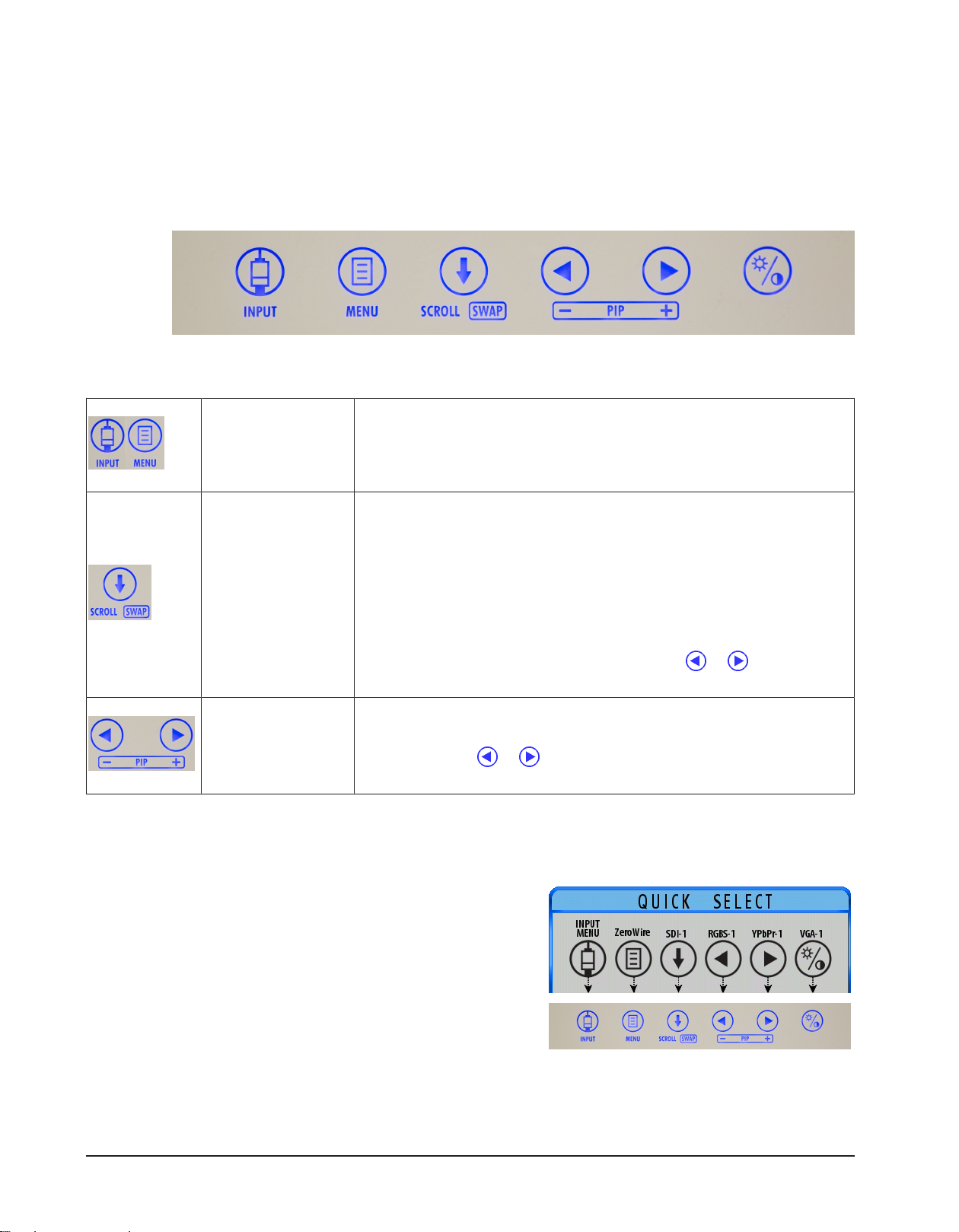
2.1 Display Keypad ................................................................................................................................................................10
2.2 Menu Navigation ............................................................................................................................................................10
2.3 QUICK SELECT: Primary Input Selection .................................................................................................................10
2.4 EDIT QUICK SELECT: Modify Availability of Primary Inputs..............................................................................11
2.5 Input Menu........................................................................................................................................................................11
2.6 Display Menu....................................................................................................................................................................12
2.7 ZeroWire Menu................................................................................................................................................................13
2.8 ZeroWire Status Messages...........................................................................................................................................14
2.9 Picture Menu ....................................................................................................................................................................15
2.10 Color Menu........................................................................................................................................................................16
2.11 Setup Menu.......................................................................................................................................................................18
2.12 Picture in Picture Controls...........................................................................................................................................23
2.13 Image Adjustment..........................................................................................................................................................24
3 Enclosure Assembly and Cleaning .......................................................................................................... 25
3.1 Cable Cover Installation................................................................................................................................................25
3.2 Cleaning Instruction ......................................................................................................................................................25
4 Connector Panels...................................................................................................................................... 26
4.1 Radiance Ultra Product Configurations..................................................................................................................26
4.2 Radiance Ultra Connector Panels..............................................................................................................................27
4.3 Data Connectors and Pinouts.....................................................................................................................................28
4.4 Control Connectors and Pinouts...............................................................................................................................30
4.5 Electrical Symbols...........................................................................................................................................................32
5 Specifications and Supported Resolutions ............................................................................................ 33
5.1 Specifications ...................................................................................................................................................................33
5.2 Supported Resolutions .................................................................................................................................................34
6 ZeroWire® Embedded Technology ......................................................................................................... 36
6.1 Intended Use and Warnings .......................................................................................................................................36
6.2 ZeroWire Specifications................................................................................................................................................37
6.3 Zero Wire Transmitter Setup ......................................................................................................................................39
6.4 ZeroWire G2 Transmitter Connector Panel ...........................................................................................................39
6.5 ZeroWire G2 Transmitter ‘Y’ Adapter Cables ........................................................................................................40
6.6 ZeroWire G2 Transmitter Power Supplies..............................................................................................................40
6.7 Positioning and Orientation .......................................................................................................................................41
6.8 ZeroWire Quick Start Linking......................................................................................................................................44
6.9 Wireless Linking Status Messages.............................................................................................................................45

7 Troubleshooting....................................................................................................................................... 47
7.1 Display Troubleshooting..............................................................................................................................................47
7.2 ZeroWire Troubleshooting..........................................................................................................................................48
8 Electromagnetic Compatibility Tables ................................................................................................... 50
8.1 Guidance and Manufacturer's Declaration - Electromagnetic Emissions ..................................................50
8.2 Guidance and Manufacturer's Declaration - Electromagnetic Interference Immunity .........................51
8.3 Guadance and Manufacturer's Declaration - Recommended Separation Distances.............................52
9 Terms and Conditions .............................................................................................................................. 53
9.1 Declarations of Conformity .........................................................................................................................................53
9.2 Legal Statement ..............................................................................................................................................................54

7 / 56
Safety Information | 7
1 Safety Information
1.1 Warnings and Cautions
CAUTION!
This product is a Class I medical device. No modifications are allowed.
NOTE!
This equipment/system is intended for use by healthcare professionals only.
NOTE!
There are no user serviceable parts inside. Refer servicing to qualified service personnel.
This symbol alerts the user that important information regarding the installation and/or operation
of this equipment follows. Information preceded by this symbol should be read carefully.
This symbol alerts the user that the user manual and translated copies are published on the NDS
website at: www.ndssi.com/user-manuals/
This symbol warns the user that un-insulated voltage within the unit may have sufficient mag-
nitude to cause electrical shock. Do not touch any part inside the unit. To reduce the risk of electric
shock, DO NOT remove the cover or back.
WARNING!
Fire and shock hazard
Do not expose this product to rain or moisture.
This symbol alerts the user that information preceded by this symbol should be read carefully to
avoid damage to the equipment.
This symbol denotes the manufacturer.
This symbol denotes the manufacturer’s European Community representative.
This symbol indicates compliance with the Waste Electrical and Electronic Equipment Directive
(WEEE Directive).

8 / 56
8 | Safety Information
This symbol indicates the device is a Medical Device. This product is intended only for use by
healthcare professionals in professional healthcare environments.
This product is T.U.V. approved with respect to electric shock, fire and mechanical hazards only in
accordance with CAN/CSA C22.2 No. 60601-1 and ANSI/AAMI ES60601-1.
This product meets the requirements of EN60601-1 so as to conform to the 2017/745 Medical
Device Regulation of European Union.
CAUTION!
In case of serious incident
Please report any serious incident that has occurred in relation to the device to the manu-
facturer and the competent authority of the State in which the user and/or patient is estab-
lished.
Federal (USA) law restricts this device to sale by or on the order of a physician.
1.2 System Safety Requirements
External equipment connected to the signal input/output or other connectors of this product for use in a pa-
tient environment must comply with the requirements of ISO and UL/EN/IEC 60601-1 safety standards. A per-
son who connects such equipment to this product has by definition formed a system, and is responsible for
compliance of that system to the same ISO and UL/EN/IEC 60601-1 safety standards.
1.3 Grounding
This product is energized from an external electrical power source for 2017/745 Medical Device Regulation of
European Union Class I equipment. It is the responsibility of the installer to test the product's earth ground to
verify that it complies with the hospital, local and national impedance requirements.
A ground post is located on the back of the product to use for grounding the chassis of the unit. Any such
grounding must be installed in accordance with applicable electrical codes.
1.4 Power Requirements
1.4.1 Power Supply
This product complies to the listed safety standards only when used with the supplied medical grade power
supply:
Model Radiance Ultra
Power Supply BridgePower BPM150S24F06
AC Input 100 - 240 Volts, 50 to 60 Hz
DC Input 24 Vdc, 6.25 A, 150 W

9 / 56
Safety Information | 9
1.4.2 Power Cord
Use a hospital grade power cord with the correct plug for your power source.
Disconnect the power cord from the AC mains. The power cord is the only recognized disconnect device.
MEDICAL EQUIPMENT should be positioned so that the disconnect device is readily accessible.
Monitors should be powered from a center tapped circuit when used in the US at voltages over 120volts.
1.5 Intended Use and Contraindications
1.5.1 Intended Use
Note: If your display is configured with embedded ZeroWire, please refer to ZeroWire Intended Use and Warn-
ings [}36].
Radiance Ultra series monitors are intended for use in a medical environment to display high quality video and
graphic images.
This product is intended for continuous operation.
This product is capable of displaying Radiology (PACS) images for reference only, and is not intended for dia-
gnostic use.
1.5.2 Contraindications
CAUTION!
Do not use this product in the presence of flammable anesthetics mixture with air, oxygen
or nitrous oxide.
CAUTION!
No part of this product may come in contact with a patient. Never touch the product and a
patient at the same time.
CAUTION!
For mission critical applications, we strongly recommend that a replacement unit be imme-
diately available.
1.5.3 Image Retention Warning
WARNING!
Leaving a fixed (constant) image on the monitor for a long period of time can result in im-
age retention. Avoid leaving a fixed image on the monitor, or turn the monitor off when it is
not in use.

10 / 56
10 | Display User Interface
2 Display User Interface
2.1 Display Keypad
The Display Keypad is centered on the lower front surface of the display enclosure, providing controls for ad-
justment of display parameters using the On Screen Display (OSD) Menu system.
2.2 Menu Navigation
MENU Buttons
Open OSD Menus
To open the Input Menu (see Input Menu [}11]), tap the INPUT but-
ton twice. To open the Display Menu (see Display Menu [}12]), tap
the MENU button once.
SCROLL Button
Vertical Selection Control
To enter a menu and begin a parameter selection process, tap the
SCROLL button. The top parameter row is selected with the first tap,
and the selection moves downward to the next row with each success-
ive tap.
To exit a menu, use the SCROLL button to move the selection to the
bottom menu row, and then press the SCROLL button just once to
highlight the menu tab, where you can use the or buttons to se-
lect another menu tab.
LEFT/RIGHT Button
Horizontal Selection Controls
To adjust a parameter, select the parameter row using the SCROLL but-
ton, then tap the or buttons to make the adjustment or to select
a setting.
2.3 QUICK SELECT: Primary Input Selection
To display the QUICK SELECT menu, tap the INPUT button (Display Keypad [}10]).
The QUICK SELECT menu allows the user to select any active in-
put as Primary with a single tap on the Keypad button under the
QUICK SELECT icon labeled with the target input. QUICK SELECT
icons designating active inputs are tinted light blue. QUICK SE-
LECT options apply only to selection of a Primary input. If an in-
put selected as Primary is in current use by a Secondary input be-
ing displayed as PIP, the PIP image will clear and display as a Full
Screen Primary image.
The QUICK SELECT menu closes 30 seconds after the last selection is made.
The QUICK SELECT menu can be customized to display inputs not included in the default listing using the EDIT
QUICK SELECT menu.

11 / 56
Display User Interface | 11
2.4 EDIT QUICK SELECT: Modify Availability of Primary Inputs
To display the EDIT QUICK SELECT menu, press and hold the INPUT button for three seconds (Display Keypad
[}10]).
To change a QUICK SELECT button assignment, tap the Keypad
button under the EDIT QUICK SELECT icon that is labeled with the
input assignment you want to change.
Each tap of the Keypad button displays in descending order the
next input as listed in the Input Menu. Tap the button until the
desired input appears. All buttons except the INPUT and MENU
button are available for reassignment.
2.5 Input Menu
The Primary image is designated by selection of a Primary input. If a Secondary input is selected, the Primary
image will share the screen display with a Secondary image that is presented in configurations ranging from
small to large Picture-In-Picture (PIP) to equal halves of Split-Screen displays. See Picture in Picture Controls
[}23].
To select Primary and Secondary Inputs from a single display, tap the INPUT button twice to access the Input
menu (see Display Keypad [}10]). The first (left) column is for designating the Primary input, indicated with
the letter P. The second column contains the selection cell which is moved to the input row beneath it with
each tap of the SCROLL button. The third column displays either an S for a selected Secondary input, or an X
signifying “unavailable for input”.
To position the selection cell on the row of a desired input, tap the SCROLL button as many times as needed.
To make that input the Primary input, tap the button, or to make it the Secondary input, tap the button.
A Secondary input can be cleared by positioning the selection cell on the row of the input, and tapping the
button. Inputs marked with an X in the Secondary column are unavailable for designation as a Secondary in-
put.
The Input menu will automatically close 30 seconds after the last action. It can also be closed by tapping the
INPUT button.
The following table shows which inputs may be selected as Secondary relative to inputs selected as Primary.

12 / 56
12 | Display User Interface
Inputs marked with a ✓ in the Secondary columns can be designated as the Secondary input. Gray cells denote
inputs sharing a common connector or electronics that cannot be used simultaneously.
DVI-1, VGA-1, RGBS-1, YPbPr-1 and SOG-1 share the same connector. If one is selected as the Primary input, the
others cannot be selected as Secondary. The same is true for VGA-2, RGBS-2, YPbPr-2 and SOG-2. Some inputs
are not available in some configurations.
Primary Secondary
Input
DVI-1,
VGA -1,
RGBS-1,
YPbPr-1,
SOG-1
SDI-1 DVI-2
VGA-2,
RGBS2,
YPbPr-2,
SOG-2
SDI-2 COMPOSITE S-VIDEO HDBaseT-1 HDBaseT-2
DVI-1, VGA
-1, RGBS-1,
YPbPr-1,
SOG-1
✓ ✓ ✓ ✓ ✓ ✓ ✓ ✓
SDI-1 ✓ ✓ ✓ ✓ ✓ ✓ ✓ ✓
DVI-2 ✓ ✓ ✓ ✓ ✓ ✓
VGA-2,
RGBS2,
YPbPr-2,
SOG-2
✓ ✓ ✓ ✓ ✓ ✓
SDI-2 ✓ ✓ ✓ ✓
COMPOSITE ✓ ✓ ✓ ✓ ✓
S-VIDEO ✓ ✓ ✓ ✓ ✓
HDBaseT-1 ✓ ✓ ✓
HDBaseT-2 ✓ ✓ ✓
2.6 Display Menu
To open the Display Menu, tap the MENU button. The ZeroWire
Menu displays by default, with details of the current Primary and
Secondary inputs listed left and right across the top of the menu
above the menu tabs.
To select other menus, tap the or button to highlight the
menu tab, then tap the SCROLL button to enter the menu.
To adjust a parameter, press the SCROLL button to move the row
selection down to it, and then tap the the or button to ad-
just the parameter or to select a setting. Parameter adjustments
are applied in real time while changing values or settings.
The Display Menu automatically closes 30 seconds after the last
action. It can also be closed by pressing the MENU button.
Note: Grayed out descriptions indicate parameters not available for the current signal or input configuration.

13 / 56
Display User Interface | 13
2.7 ZeroWire Menu
NOTE!
The ZeroWire Menu is enabled only on displays configured with an embedded ZeroWire Re-
ceiver.
To enter the menu and activate the ZeroWire linking process, tap the SCROLL button.
Refer to Zero Wire Transmitter Setup [}39], and confirm that the display-mounted ZeroWire Transmitter is fa-
cing the ZeroWire embedded Receiver display at a distance ≤8 feet (2.4 meters), and that both displays are
aligned vertically and horizontally within ±10° at heights ≥ 5 feet (1.5 meters).
Linking LED
At the display-mounted ZeroWire Transmitter, press and hold the LINK button until the Linking
LED begins flashing.

14 / 56
14 | Display User Interface
At the ZeroWire embedded Receiver display, begin the ZeroWire linking process by tapping the button.
The display of the ZeroWire embedded Receiver unit will go black when the Primary Input is automatically
switched to ZeroWire. A series of linking status messages in the lower corner of the display will indicate pro-
gressive stages in the linking process. When linking is complete, the Transmitter display image will appear on
the Receiver display.
For an alternative ZeroWire linking procedure, see ZeroWire Quick Start Linking [}44].
2.8 ZeroWire Status Messages
ZeroWire status messages indicate stages of the linking process.
Refer to Wireless Linking Status Messages [}45] for complete descriptions of all status messages.

15 / 56
Display User Interface | 15
2.9 Picture Menu
To access the Picture Menu, tap the button once after opening the Display Menu.
Horizontal Position
To horizontally center the image, tap the or button.
Vertical Position
To vertically center the image, tap the or button.
H-Sharpness
To increase sharpness (edge enhancement) of the displayed image in the Horizontal plane, tap the or
button.
V-Sharpness
To increase sharpness (edge enhancement) of the displayed image in the Vertical plane, tap the the or
button.
Phase (VGA, RGBS, YPbPr, and SOG only)
To adjust phase of the display pixel clock, tap the or button.
Frequency (VGA, RGBS, YPbPr, and SOG only)
To adjust frequency of the display pixel clock until the image fills the screen horizontally, first set Scaling to Fill,
and tap the or button.
Overscan (Video)
Parameter enabled when the input is 16:9, 480P, 576P, or interlaced. Tap the or button to select.
0: The image is displayed at a size that fills the screen without losing any video information. Image could be
displayed as letterboxed, with black bars top and bottom or left and right.
1, 2, 3, 4, 5 or 6: Incrementally enlarges and crops the centered image. As the image becomes larger, video in-
formation is lost on all sides.
Scaling (Graphics)
Parameter enabled when input signal is not 16:9, 480P, 576P, or interlaced. Tap the or button to select.
Fill: Expands the video image to fill the entire screen. The aspect ratio may not be accurately displayed.
Aspect: Expands the video image until its largest dimension fills the screen while retaining the aspect ratio.
The image may be displayed as letterboxed, with black bars top and bottom or left and right.
1:1: Displays the video data in its native size and aspect ratio. Image with aspect ratios different from that of
the display are letterboxed, with black bars top and bottom or left and right.

16 / 56
16 | Display User Interface
SmartSync™/Alternative Modes: (VGA, RGBS, YPbPr, and SOG only)
NDS proprietary SmartSync technology examines incoming signals to automatically display the video image in
its proper format.
Alternative Modes are used to manually distinguish between modes whose timing characteristics are very
close.
SmartSync: To enable SmartSync, tap the RIGHT button.
Alternative Modes: To make an Alternative Modes adjustment, tap the button. After selecting Alternative
Modes the mode changes incrementally each time the button is tapped until the selected mode equals the
maximum available. The next tap of the button restores the initial mode.
Flip/Rotate
Tap the or button to select one of 5 options:
H-Flip V-Flip 90° 180° 270°
Left to right flip Top to bottom flip Clockwise rotation Clockwise rotation Clockwise rotation
Fine Tune
Currently not available.
2.10 Color Menu
Gamma
To select a gamma setting, tap the or button.
1.8, 2.0, 2.2, 2.4 or 2.6: Preset gamma values
Video: Linear gamma Look Up Table (LUT)
PACS: DICOM gamma LUT
This product is capable of displaying Radiology (PACS) images for reference purposes only.
Color Temperature
To select a preset color temperature, tap the or button.
5500, 6500, 8000, 9300: Preset color temperatures.
User: With a preset color temperature selected, if any other Color parameter is subsequently adjusted from
the default setting, the resulting values are copied to the Color Temperature User presets and User is selected.

17 / 56
Display User Interface | 17
Red / Green / Blue
To adjust balance of the selected color in the image, tap the or button.
Saturation (available only for YUV inputs)
To adjust saturation (color intensity) of the image, tap the or button.
Hue (available only for YUV inputs)
To adjust hue (color) of the image, tap the or button.
Brightness
To adjust brightness, tap the or button. Brightness is also controlled by the Brightness/Contrast button
described in Image Adjustment [}24].
Contrast
To adjust contrast, tap the or button. Brightness is also controlled by the Brightness/Contrast button
described in Image Adjustment [}24].
Video Level
To adjust signal range, tap the or button.
Normal: Provides a dynamic range equivalent to the incoming signal with no change.
Expanded: Expands the signal level such that an input signal with range 16 (black) to 235 (white) will be ex-
panded to a range of 0 (black) to 255 (white).
NOTE!
If a signal is already full range (0 to 255), selecting the Expanded setting will cause the sig-
nal to “clip” or “saturate.”
Color Correction
To select a color correction setting, tap the or button.
User: Default values replaced by user modified settings.
NDS: Factory calibrated to match NDS specifications of 2.2 gamma/6500K color temperature.
SMPTE-C: Factory calibrated to meet the SPMTE-C standard.
BT-709: Factory calibrated to meet the BT-709 standard.

18 / 56
18 | Display User Interface
2.11 Setup Menu
Menu Position
To select from nine preset screen locations for display of the OSD menu, tap the or button.
Language
To select one of eight languages: English, Deutsch, Français, Italiano, Svenska, Español, Nederlands, or
Pycckий, tap the or button.
DPMS Enable
To enable or disable Display Power Management System (DPMS), tap the or button.
Off: Default setting.
On: If there is no input signal, a D.P.M.S message displays for 10 - 15 seconds before the display goes into
Power Saving mode. The display turns on when the input signal is restored.
Auto Source Select
To disable or enable Auto Source Select, tap the or button.
Off: Video input is manually selected.
On: Searches through all possible input sources until an active video source is found.
Priority: Priority Input Select is by default disabled. A Secondary input must be selected before Priority Input
Select can be enabled. When the Priority Input Select function is enabled, the PIP image is placed behind the
Primary image, the PIP + and - ( and ) buttons are disabled, and the SWAP button remains enabled. If the
Primary signal is lost, the Secondary input is displayed. If the Primary signal is restored, its image is displayed
again, and the Secondary image is placed behind the Primary image. If both the Primary and Secondary sig-
nals are lost, the monitor alternately scans the Primary and Secondary inputs until a signal is detected on one
of them. When a signal is detected on the Primary or Secondary input, its image is displayed on the monitor.
Menu Lock
To enable Menu Lock, press the button.
Off: Default setting.
On: Disables access to OSD menus to prevent inadvertent changes to display settings. The OSD closes, and a
MENU LOCKED message displays briefly. To unlock OSD access, simultaneously press and hold the MENU and
SCROLL buttons until a MENU UNLOCKED message displays.

19 / 56
Display User Interface | 19
Communication Port
To select a Communication Port for control of the display using NDS Unified Serial Commands, tap the or
button. For connector details, see Data Connectors and Pinouts [}28].
RS-232: Connect an RJ-25 cable to the RS-232 port.
Ethernet: When the Ethernet port is selected, the display can be controlled through the TCP/IP port.
Note: When using the Ethernet Communication Port selection, verify the Network IP Address: Port, Subnet
Mask and Gateway settings described in Setup Menu [}18] are correctly configured for your network.
USB: A mini-USB cable used with the USB (ND-OS) port will appear to the connecting device as an RS-232 port.
DVI-1 Output
To change Redrive or Screen settings, tap the button, which toggles selection between the two settings.
Redrive: Outputs DVI-1 signal input to DVI-1 RE-DRIVE (Output) connector.
Screen: Outputs display image, including PIP and OSD, to the DVI-1 RE-DRIVE (Output) connector.
Display Image: DVI-1 + VGA
Redrive: DVI-1 to DVI-1 Output Screen: DVI-1 + VGA to DVI-1 Output
Keypad Color
To modify the Keypad color setting, tap the or button.

20 / 56
20 | Display User Interface
Factory Defaults
To return all settings to factory preset values, tap the button to open the Factory Defaults menu.
Next, tap the SCROLL button to select the Factory Defaults function, and tap the button. The Restoring
Factory Defaults message displays while processing.
User Defaults
To save changes to default parameters in a User Default profile, tap the SCROLL button to select a User De-
faults profile marked Empty, and tap the button to save the profile. The Saving User Defaults message dis-
plays while processing.
To restore a User Defaults profile after changing other parameters, select the saved User Defaults profile and
tap the button. The Restoring User Profile message displays while processing. To clear a User Defaults pro-
file, select the saved User Defaults profile and tap the Brightness/Contrast button. The Clearing User Profile
message displays while processing.
Table of contents
Other NDS Medical Equipment manuals

NDS
NDS ExpandOR User manual

NDS
NDS EndoVue Plus 15" User manual

NDS
NDS 90R0123 User manual

NDS
NDS RADIANCE G2 User manual

NDS
NDS ZeroWire Mobile User manual

NDS
NDS EndoVue Plus 15" User manual

NDS
NDS RADIANCE G2 User manual

NDS
NDS ConductOR User manual

NDS
NDS ZeroWire Mobile User manual

NDS
NDS ExpandOR User manual