Nedap PowerRouter User manual
the PowerRouter
PowerRouter Solar Battery
Installation Manual
1
2
3
4
5
6
200 A
NNL
L
AC GRID AC LOCAL OUT
NO NO
NC NC
AC LOCAL OUTAC GRID
mounting bracket
690 mm max. ø 5.5 mm
600 mm max. ø 10 mm
570 mm max. ø 5.5 mm
370 mm
Standby
1 2 3
4 x
4 x
2 x
2 x
4 5 6
Standby
+
Standby
Standby
Standby Standby
Standby
Standby
Standby
min. 300 mm
min. 800 mm
Max.40°C
Min.-10°C
!
i
20 KG
A
A
A
A
A
B
B
Drill template for the PowerRouter
Drilltemplate for the PowerRouter Drilltemplate for the PowerRouter
Installation steps
Partno. 5555426,1
Read the installation manual for details
the PowerRouter
-
+

+B AT
-B AT
TMPS
GND
SH+
SH-
Red +
Fuse
300 A
Temperature
sensor
- Black
7
8
9
10
11
12
AC LOCAL OUTAC GRID
USB
ETHERNET RJ45
CAN BUS CAN
NO NO
NC NC
AC GRID AC LOCAL OUT
2
1
internet router
PC, laptop, Mac to the router
Cat5 network cable of a suitable length
the PowerRouter to the router
ADSL/ISDN/cable connection
power adapterto the router
1
2
34
1
2
3
4
6
5
5
6

Main menu
History
menu
Settings
menu Service
menu
Status
menu
System Reset
Selftest
Errors
Install
Wizard
Display
Date&Time
Language
Battery
Solar
Grid
Battery
Solar
Grid
Internet
connections
13
14
YES
NO
ON
OFF
Operational
Grid
Charging
Error

EN
FR
IT
ES
PT
DE
NL
Installation manual
Page 6
Installationshandbuch
Seite 20
Manuel d’installation
Page 34
Installatie handleiding
Bladzijde 48
Manuale d'installazione
Pagina 62
Manual de instalación
Página 76
Manual de instalação
Página 90
N.V. Nederlandsche Apparatenfabriek “Nedap”
The Netherlands
PowerRouter Solar Battery
3000W, 3700W and 5000W

EN
6
Safety Information
This manual contains instructions for the PowerRouter that should be followed during installation, operation and maintenance of the unit.
The PowerRouter is designed and tested according to international safety requirements. To reduce the risk of personal injury and to ensure
safe installation and operation of the PowerRouter, carefully read and follow all instructions, cautions and warnings in this installation
manual.
The warning symbol indicates a hazard to either the equipment or personnel. It draws attention to a procedure which, if not correctly
executed, may result in damage to the PowerRouter or to the connected equipment. It could also result in personal injury.
Danger
This symbol indicates a hazardous situation which, if not avoided, will result in death or serious injury.
Warning
This symbol, when used alone or in conjunction with any of the following icons, indicates the need to consult the operating instructions
provided with the product. A potential risk exists if the operating instructions are not followed.
Caution
This symbol indicates a hazardous situation which, if not avoided, could result in minor or moderate injury.
Information
This symbol accompanies notes that call attention to supplementary information that you should know and use to ensure optimal operation of
the system.
A bullet with a number refers to an illustration with the same number. For illustrations refer to pages 2-4.
Contents
To help avoid problems during the installation, familiarize yourself with the installation process by reading the entire installation manual before
starting the installation.
Lethal voltages are present at various points in a solar system. For safety reasons, it is recommended that only qualified personnel install and
operate this equipment.
Lethal currents are present within the battery. When the battery terminals are short circuited, sparks may create burnmarks or a fire hazard.
!
DANGER
!
WARNING
!
CAUTION
i
1
i
!
DANGER
Safety Information................................................................................................................................................................................................6
Contents................................................................................................................................................................................................................6
1 Introduction........................................................................................................................................................................................................7
2 Safety..................................................................................................................................................................................................................7
3 Mounting ............................................................................................................................................................................................................7
3.1 Choosing a mounting location ......................................................................................................................................................................7
3.2 Dimensions and recommended clearances ................................................................................................................................................8
3.3 Mounting procedure.......................................................................................................................................................................................8
4 Wiring..................................................................................................................................................................................................................8
4.1 Wiring AC Connections..................................................................................................................................................................................8
4.2 Wiring Solar connections...............................................................................................................................................................................9
4.3 Wiring battery and sensor connections .......................................................................................................................................................9
4.4 Bypass switch (for the professional models)...............................................................................................................................................9
4.5 Internet connection......................................................................................................................................................................................10
4.6 Optional CAN-bus.........................................................................................................................................................................................10
4.7 Free programmable general purpose contacts.........................................................................................................................................10
5 Commissioning................................................................................................................................................................................................10
6 Operation .........................................................................................................................................................................................................11
6.1 Navigating .....................................................................................................................................................................................................11
6.2 Service menu ................................................................................................................................................................................................11
7 Malfunctions and errors..................................................................................................................................................................................13
8 Cleaning and maintenance.............................................................................................................................................................................13
9 Decommissioning............................................................................................................................................................................................14
10 Disposal..........................................................................................................................................................................................................14
Appendix A Warranty........................................................................................................................................................................................15
Appendix B Error codes...................................................................................................................................................................................16
Appendix C Technical Specifications .............................................................................................................................................................18
Appendix D PV-MS tool....................................................................................................................................................................................19
Notes ...................................................................................................................................................................................................................19

EN
7
1 Introduction
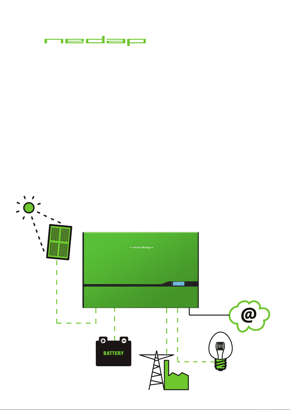
This manual is suitable for the PowerRouter Solar Battery types: PR30SB (3000W), PR37SB (3700W) and PR50SB (5000W).
The manual is intended for certied installers to mount, wire and commission the PowerRouter unit.
The PowerRouter is a DC to AC grid-tied utility unit for use with Photovoltaics (PV) and battery backup storage. The PowerRouter can be
used for feed-in purposes. The optional AC local output of the PowerRouter supplies a no-break supply to the connected load in the event
of a grid failure. For more information visit: www.PowerRouter.com.
2 Safety
Before installing or using the PowerRouter, read all of the instructions, cautions, and warnings on the PowerRouter, the solar array and
battery bank and in this installation manual. Before connecting the PowerRouter to the electric grid, contact the local utility company. Solar
arrays produce electrical energy when exposed to light and can thus create an electric shock hazard. Wiring of the solar arrays should only be
performed by qualified personnel. To prevent short circuiting of the battery, an isolated box wrench should be used.
The PowerRouter contains no user-serviceable parts. For all repairs and maintenance, contact your installer/dealer.
Anti-islanding protection
The PowerRouter has a built-in anti-islanding protection functionality in compliance with local regulations.
During a utility failure, the PowerRouter unit will disconnect from the grid. With the optional "Local Out" you may continue supplying your
loads in this event.
Solar Series fusing
Serial fusing may be required depending on the type of PV module and conguration used in the system.
CE Compliance
The PowerRouter is compliant according to CE Directive.
3 Mounting
This chapter provides guidelines to help select the best mounting location, provides suggestions to ensure optimum performance, cautions
and warnings that you should follow in order to avoid injury and equipment damage. Also included are step-by-step instructions for
mounting the PowerRouter.
3.1 Choosing a mounting location
Take into account the following guidelines, cautions, and warnings when choosing a mounting location for the PowerRouter:
• The PowerRouter is designed for indoor installations (IP21)
• Do not install the PowerRouter in direct sunlight
• Do not install the PowerRouter on ammable construction materials
• Do not install the PowerRouter in areas where highly ammable materials are stored
• Do not install the PowerRouter in potentially explosive areas!
• Do not install the PowerRouter during periods of precipitation or high humidity (>95%); moisture trapped within the location may cause
corrosion and damage to the electronic components
• Provide adequate ventilation when using batteries, and also read the warning label on the bottom of the PowerRouter
• Install the PowerRouter in a location that maintains an ambient air temperature that is less than 40 °C; this is to maintain a safe internal
component temperature, the PowerRouter reduces power if the ambient air temperature exceeds 40 °C
• The PowerRouter should be installed in a location that is not accessible for children
• The PowerRouter emits a slight vibrating noise when operating. This noise is normal and has no effect on performance, but it can
be disturbing if the unit is mounted on a wall in a living area, on the outside of a wall that is near a living area, or on certain types of
materials, such as thin wood panelling or sheet metal
• The slope of the wall should be within ± 5°
• The PowerRouter weighs 20.5 kg; ensure that the mounting surface is strong enough to hold the weight of the PowerRouter
• The bottom of the PowerRouter is provided with a label showing the ratings; the PowerRouter must be mounted in such a manner that
this label remains visible after installation, as the label contains a serial number needed as a login code for the install wizard and to
register at www.myPowerRouter.com for logging and monitoring
If you are installing the PowerRouter in a cabinet, closet or other relatively small enclosed area, sufficient air circulation must be provided
in order to dissipate the heat generated by the unit. To prevent electric shock or other injury, check for existing electrical or plumbing
installations in the walls before drilling mounting holes for the PowerRouter.
!
WARNING
1
i

EN
8
3.2 Dimensions and recommended clearances
Mount the PowerRouter with 300 mm clearance at the top and bottom of the unit. If more PowerRouters are stacked, then use a clearance
of 800 mm between each PowerRouter. Use the drill template provided with the PowerRouter for drilling the bracket and mounting holes.
Ensure that there is sufficient clearance for the airflow around the PowerRouter! Local regulations may require larger working clearances.
Dimensions of the PowerRouter are 765 x 502 x 149 mm (W x H x D).
3.3 Mounting procedure
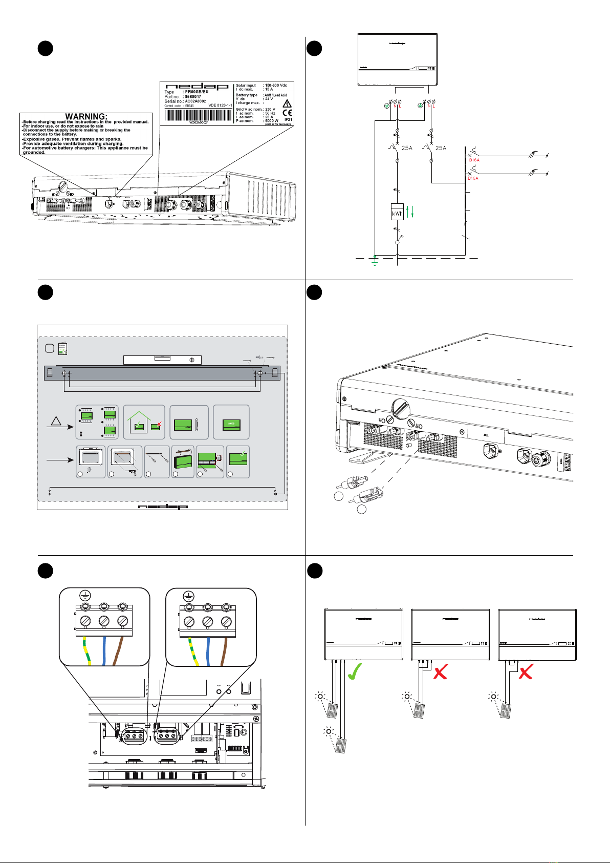
The PowerRouter is shipped with a wall-mounting bracket that is suitable for use on most walls.
Mounting procedure:
1. Use the drill template provided with the PowerRouter (follow the illustrated instructions on the drill template)
2. Drill holes for the mounting bracket in the wall (if required)
3. Drill holes for securing in the wall (if required)
4. Mount the mounting bracket
5. Install the PowerRouter on the mounting bracket
6. Open front cover and secure with screws (use screwdriver with a blade-length of 160 mm)
4 Wiring
This chapter provides step-by-step instructions and other information required for wiring the PowerRouter to the PV array, battery, the utility
grid and the optional local out. To complete the installation in a safe and efcient manner, follow the steps in the right order.
Before wiring the PowerRouter, make sure that all wires connected to the PowerRouter are not live by turning off all disconnects and/or
switches.
Wiring steps:
1. Use the quick installation sheet provided with the PowerRouter
2. Connect the wires of the AC voltage from the utility grid and the load to the PowerRouter (refer to clause 4.1)
3. Connect the wires of the DC voltage from the PV array and battery to the PowerRouter (refer to clause 4.2 and 4.3)
4.1 Wiring AC Connections
This clause describes the AC connections of the PowerRouter to the AC grid and the optional AC local out.
Use 4 mm² wires.
Wiring AC connection steps: (step 5,6 and 7 are optional)
1. Strip the insulation off the wires and pass the wires through the gland opening
2. Connect the AC Grid ground wire to the AC Grid ground terminal
3. Connect the AC Grid Line (L) wire to the AC Grid terminal labeled L
4. Connect the AC Grid Neutral (N) wire to the AC Grid terminal labeled N
5. Connect the AC Load ground wire to the AC Local Out ground terminal
6. Connect the AC Load Line (L) wire to the AC Local Out terminal labeled L
7. Connect the AC Load Neutral (N) wire to the AC Local Out terminal labeled N
8. Tighten strain reliefs
Example of an electrical residential installation.
Verify that all connections are correctly wired and properly torqued (min. 1.2 Nm, max. 1.5 Nm).
Contacts need to be free of any mechanical strain.
2
i
2
3
4
i

EN
9
4.2 Wiring Solar connections
This clause describes the connection between the solar panels and the PowerRouter.
Before connecting the PV string connectors to the PV terminals check this list:
Set DC switch on the PowerRouter to OFF
• Use copper wire (4 mm2) for all PV wiring connections to the PowerRouter; apply only solid or stranded wire. Do not use ne stranded
wire
• Verify that the DC solar current and voltage of your installation does not exceed the maximum rates specied on the type rating label
• Check the polarity of the PV strings
• Use special tool for connecting MC4 connector on the PV wires; the PV MS tool is described in Appendix D
Connect 1 or 2 strings to the PV input terminals using mating MC4 connectors.
The 3kW unit only has 1 PV input.
Do not connect 1 PV-string to both PV-terminals simultaneously (parallel connection).
Do not connect 1 PV-string to both PV-terminals in serial.
4.3 Wiring battery and sensor connections
This clause describes the connection between the PowerRouter and the battery and temperature sensor.
Do not connect the battery before commisioning, refer to Chapter 5.
Battery connection:
1. Apply battery cable with a diameter of at least 95 mm2, maximum 2.5 m length per cable
2. Fit a fuse (300 A slow blow) in the positive battery cable as close as possible to the battery
3. Strip approx. 25 mm cable insulation
4. Insert cable into the terminal (red to positive terminal, black to negative terminal)
5. Tighten the cable connection with a hex driver (6 mm) (torque 15Nm - 20Nm)
6. Use cable lug (eyelet terminal) on the other end of the battery cable
Temperature sensor connection:
1. Connect sensor wires to TMPS (red wire) and GND (black wire) terminals in the PowerRouter
2. Stick the self adhesive temperature sensor onto the battery near the (+) pole
Verify that the battery connections are correctly wired and properly torqued. Connecting a battery can cause a spark.
Miswiring can cause damage to the PowerRouter. Read the label on the battery.
Battery charging stations must be located in designated battery charging areas. This is because of the dangers of hydrogen gas and battery
acid.
Do not smoke or bring open flames near hydrogen gas. Wear protective gear when working with batteries.
The temperature sensor is used for battery charge control and safety.
4.4 Bypass switch (for the professional models)
This clause describes the usage of a bypass switch.
The PowerRouter professional models use the 'Local Out' to supply your loads. This unique feature enables it to supply backup power in the
event of a grid failure, as a PowerRouter with a 'Local Out' connection can switch to 'island mode' when the grid fails. After a short delay it
resumes operation, enabling its unique 'Local Out' connection to supply a stable 230Vac power signal to the connected loads.
Bypass switches are crucial components with which the PowerRouter supports critical load situations. (The PowerRouter acts as a UPS
system). The bypass switch allows you to switch off the PowerRouter for maintenance, without cutting power to the load. When the switch
is activated, the mains supply is directed away from the PowerRouter and is directly connected to the load. The PowerRouter can then be
serviced and any maintenance work carried out without disturbing the load. Once the PowerRouter is ready to be switched on, the bypass
switch is deactivated and the supply is redirected to the PowerRouter; the load receives the PowerRouter supply again.
The Bypass switch is an optional component and should be obtained and installed separately. (Bypass switch contacts ratings = 230V 40A).
The AC grid input and AC local output circuits are isolated from the enclosure and system grounding.
AC grounding: connect the PowerRouter to the AC ground from the utility via the ground terminal (PE).
PV Grounding: check local regulations. DC Grounding Electrode Conductor: a DC grounding electrode conductor may be required by the
local authorities. The AC local out connection of the PowerRouter is an optional connection, depending on how the PowerRouter will be
used.
5
6
!
CAUTION
7
!
CAUTION
i
8
i

EN
10
4.5 Internet connection
This clause describes the connection of the PowerRouter to the internet.
When the PowerRouter is connected to the internet, the web portal myPowerRouter.com gives detailed system information (e.g.
performance, prot, solar yield) on each PowerRouter unit. The PowerRouter can even be remotely updated with new rmware containing
the latest features, so your system is always up to date.
Connecting the PowerRouter to the internet with standard UTP / RJ45 network cable to your internet router / gateway / switch.
More information about possible connections to the internet is available on www.PowerRouter.com.
The PowerRouter only uses Internet port 80, this is normally a standard setting of the network. It can be tested by connecting a PC to this
connection and trying to surf on the internet. In case of applying a proxy, contact your installer/dealer.
4.6 Optional CAN-bus
This clause describes the optional CAN-bus of the PowerRouter.
This connector is for future use and is covered with a plug to prevent misconnection with the internet port.
Check www.PowerRouter.com to nd out when this option becomes available.
4.7 Free programmable general purpose contacts
This clause describes the PowerRouter general purpose contacts functionality.
Two programmable contacts are available and the contacts are potential-free with the ratings: 230Vac - 1 A / 24Vdc - 1 A.
The contacts switch over when battery and/or grid levels are exceeded and they switch back in safe conditions. The triplevels are adjustable
with the install wizard and installation software tool; see also clause 6.2. The left contacts can be used for grid alarms, the right contacts can
be used for battery alarms.
5 Commissioning
This chapter describes the commissioning of the PowerRouter.
Before using the PowerRouter, the unit must be initialized by setting system parameters. There are 2 methods to set the system parameters:
A. Using the built-in install wizard
B. Using the software installation tool with a PC connected to the PowerRouter's USB port
Commissioning method A (recommended):
1. Switch utility grid to the PowerRouter
2. Switch the main switch of the PowerRouter to ON, the install wizard will start, set system parameters of the PowerRouter by using the
install wizard
3. Switch PV-panels (with DC switch), battery and load to the PowerRouter
Commissioning method B (for advanced settings):
1. Insert a USB cable into the USB port of the PowerRouter and to a PC.
2. Switch utility grid to the PowerRouter
3. Switch the main switch of the PowerRouter to ON, use the software installation tool and set the system parameters
4. Switch PV-panels (with DC switch), battery and load to the PowerRouter
After commissioning, the PowerRouter is ready to use.
The USB port:
The PowerRouter can be initialized by using the PowerRouter software installation tool.
Download the PowerRouter software installation tool and driver via the PowerRouter website: www.PowerRouter.com/software (you need
your login details for this website). Check the Business Partner website regularly for updates to the PowerRouter software installation tool.
Connect the PowerRouter to a PC with a standard USB B-type to A-type cable, and you can then use the software installation tool.
9
12
i
9
12
i

EN
11
6 Operation
This chapter describes the operation of the PowerRouter.
The PowerRouter has 4 buttons to operate. Navigating and changing values can be done by using these 4 buttons.
The 4 rows display shows the menus and other information like status, history and error messages. The user manual provided with the
PowerRouter explains how to operate the PowerRouter and is intended for the end-user. This chapter explains the service menu.
6.1 Navigating
Navigation buttons:
• Up / Down Scroll through the menus or list or change value
• Yes Conrm choice or select item
• No Return to previous state
6.2 Service menu
This clause provides information about the service menu.
The service menu gives access to service-related functions like Reset, Self test, Error history, internet connection and Install wizard.
Overview of the menu structure.
6.2.1 Reset
If the PowerRouter is not working as expected then a reset can help. The PowerRouter will then be restarted, and during this restart the load
will be disconnected. This means that during this event no power will be available for the end-user, depending on the conguration.
The restart duration is less than 1 minute.
Reset procedure:
1. Enter the service menu
2. Select Reset
3. Press YES to continue
4. Press YES to start the Reset procedure
The PowerRouter should work as normal, otherwise contact your installer/dealer.
6.2.2 Self test
The self test is a safety check required by some countries. During this test the PowerRouter will simulate the grid voltage and frequency, the
PowerRouter should respond safely on the simulated grid abnormalities. The test will pass if the PowerRouter responds within the country
given specications; otherwise the PowerRouter shuts down.
Self test procedure:
1. Enter the service menu
2. Select Self test
3. Press YES to start the Self test procedure
When the PowerRouter shuts down, start the PowerRouter and run the self test again. If it still fails contact your installer/dealer.
6.2.3 Error history
The error history holds the last 10 error messages which have occurred.
When contacting your installer/dealer, the error codes in the error history can be helpful to determine the problem.
Error history readout procedure:
1. Enter the service menu
2. Select Error history
3. Press YES to enter the Error history
4. Press Up/Down to scroll through the error list
13
14
i
i

EN
12
6.2.4 Install Wizard
The install wizard guides you through the setup of the system parameters.
To prevent accidental system parameter changes, the PowerRouter asks you to login (during commissioning the login is skipped).
The last 4 digits of the serial number on the rating label is used for the login code. Use the Up/Down buttons to set each digit and press the
YES button to conrm and go to the next digit until the last digit is set.
The following parameters can be set: Language, Country, Date & Time, Battery settings (Size, Current, Type, Charge, Voat, Vbulk, Low
battery alarm), AC alarm relay.
Install wizard procedure:
1. Enter the service menu
2. Select Install wizard
3. Press YES to enter Install wizard
4. Press YES to continue the wizard
5. Enter login code
6. Press YES to continue the wizard
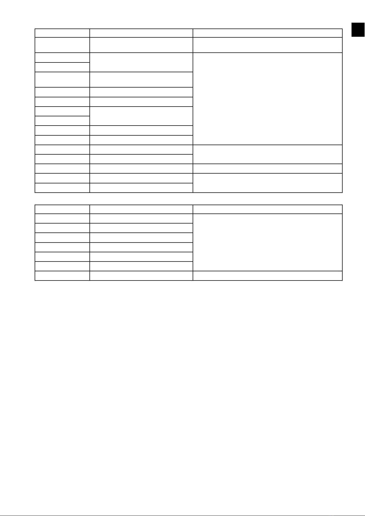
The table below shows the battery parameters which can be set during the Install wizard or the software installation tool.
Battery settings (right
relay)
Description Default
value
Minimum
value
Maximum
value
Size Capacity of the battery 400 Ah 100 Ah 40000 Ah
Current Maximum battery charge current 100 A 20 A 200 A
Type GEL or WET GEL
Charge* 3 Stage or Fix. oat charge characteristic 3 stage
Voat Charge voltage 26.4 V 26.0 V 28.0 V
Vbulk Charge voltage if 3-stage charge characteristic is set.
Will not be used if xed oat charge characteristic is set
28.8 V when
3-stage is set
28.0 V 30.0 V
Low battery alarm ON: Low battery alarm relay will be activated if battery
voltage falls below set value
22 V 19.0 V 23.0 V
OFF: Low battery alarm relay will be de-activated if battery
voltage rises above set value
24 V 24.0 V 26.0 V
* Select oat charge for UPS use - select 3 stage for cyclic use.
The table below shows the AC alarm relay parameters which can be set during the Install wizard or the software installation tool.
AC alarm relay (left
relay)
Description Default value Minimum
value
Maximum
value
AC low alarm
Minimum difference
between ON and OFF
setting is 15 V
ON: AC alarm relay will be activated if grid voltage below set
value
180 V 225 V
OFF: AC alarm relay will be de-activated if grid voltage
above set value
225 V 230 V
AC high alarm
Minimum difference
between ON and OFF
setting is 15 V
ON: AC alarm relay will be activated if grid voltage above set
value
235 V 254 V
OFF: AC alarm relay will be de-activated if grid voltage
below set value
230 V 235 V
6.2.5 Internet connection
This clause describes a check if your PowerRouter is connected to the internet.
The internet connection test procedure:
1. Enter the service menu
2. Select Internet connection
The display will show information about the internet status like: Internet connection status (ok, error, counting), Last date and time when the
PowerRouter was internet connected, IP number and status about rmware distribution.

EN
13
7 Malfunctions and errors
This chapter provides information in case of a malfunction or error of the PowerRouter.
The PowerRouter will indicate the malfunction on the unit both by the LED indicators and on the display. The malfunction may be of any
kind, either inside the unit or somewhere in the PV system. The unit will not operate until the fault has been corrected. The different error
codes and possible causes are addressed in this section. Refer to myPowerRouter.com for the latest error list.
LED indication
In case of malfunction the LEDs will either be OFF or FLASHING as follows:
Operation LED
color
LED: ON LED: OFF LED: FLASHING
Operational blue when unit is operational when unit is off or error n.a.
Charging blue when batteries are charged when unit is off or error when capacity of the batteries are lower then 30%
Grid blue when grid is connected when no grid or off Grid available not connected
Error red when error (*) n.a. when one module / function down (**)
* Requires service intervention
** Error may resolve itself; other module/functions active.
How to deal with errors
An error may prevent the system from operating. Before the system can operate again, the error has to be cleared. Errors are cleared
automatically by the system if the error condition disappears. When the error message stays, press a button (YES or NO or UP/DOWN) on
the PowerRouter to clear the error. Also the error message can be cleared using the installation software tool or via the internet.
Clear error message procedure:
1. Press NO for at least 3 seconds
Troubleshooting
If you encounter difculty with the operation of your PowerRouter, please follow these steps in an effort to correct the problem:
• Check the LED display
• Check and record the error message on the LCD display or other communication system available and take appropriate action to
correct the issue by referring to the error codes in Appendix B
• If the system problem persists, contact your installer/dealer
When contacting your installer, provide the following information:
• Serial number
• Model number
• Short description of the problem
• Display message
• Error codes listed in the Service/Error history menu
Error codes are listed in Appendix B and will also be available on myPowerRouter.com.
8 Cleaning and maintenance
This chapter describes the cleaning and maintenance of the PowerRouter.
Clean every 12 months (once per year) the housing with a dry cloth and check that there is no airow obstruction. Remove any dust build-up
from the locations as indicated. Check the PowerRouter and the cables for visible external damage on a regular basis.
When cleaning the airflow holes inside the housing, cut off the power from the PowerRouter unit by decommissioning or by using a bypass
switch.
Internal cleaning is only to be carried out by certified persons. Contact your installer/dealer if you find any defects. Do not perform any repair
work yourself.
i
!
CAUTION

EN
14
9 Decommissioning
This chapter describes the decommissioning procedure of the PowerRouter.
The decommissioning procedure is needed to safely remove the PowerRouter.
Decommissioning procedure:
1. Switch the PowerRouter unit OFF
2. Switch OFF DC-switches or disconnects (Solar / Battery)
3. Switch OFF AC-switches or disconnects (Grid / Load)
4. Wait 5 minutes for de-energizing
5. Disconnect communication and optional connections wirings
6. Disconnect battery wiring
7. Disconnect PV wiring with the special tool as described in Appendix D (Solar)
8. Disconnect AC wiring (Grid / Load)
The PowerRouter can now be removed for disposal or repair.
Decommissioning should only be carried out by certified persons. Contact your installer/dealer.
10 Disposal
This chapter describes procedures for disposal of the PowerRouter.
When the PowerRouter needs to be disposed of because it has reached the end of its life, or for other reasons, have this carried out
according to local waste handling regulations. The PowerRouter must not be disposed of with household waste. Instead, it is the end-user's
responsibility to have it disposed of by handing it over to a designated collection point for the recycling of waste electrical and electronic
equipment.
!
CAUTION

EN
15
Appendix A Warranty
PowerRouter factory warranty conditions
Our quality control program ensures that each PowerRouter product is manufactured to exact specications and is thoroughly tested before
leaving the factory.
5 year warranty
The Nedap factory warranty period is 5 years as from the purchase date of the PowerRouter system. The warranty conditions are based on
the European EU directive no. 99/44/EG. The legal rights are applied for unimpeded.
Extended warranty
For all PowerRouter systems you can acquire an extension of 5 years on the PowerRouter factory warranty, up to a total of 10 years
warranty. The warranty is only available if purchased within 6 months of the PowerRouter delivery date.
Warranty conditions
If a PowerRouter becomes defective during the relevant PowerRouter warranty period, one of the following services, as selected by the
PowerRouter Helpdesk, will be performed at no charge for materials, exclusive of labor costs:
• Repair at Nedap N.V., or
• Repair on-site, or
• Exchange for a replacement unit (of equivalent value according to model and age)
Exclusion of liability
Warranty claims and liability for direct or indirect damage are excluded if arising from:
• Transport and storage damage
• Incorrect installation and/or commissioning
• Modications, changes or attempted repairs by untrained and unauthorized personnel
• Incorrect use or inappropriate operation
• Insufcient ventilation of the unit
• Failure to observe the applicable safety regulations
• Force majeure (e.g. lightning, overvoltage, storm, re)
• Cosmetic shortcomings which do not inuence the functioning of the unit
• Damage due to moisture and/or other environmental conditions
The installer/dealer who installed the PowerRouter must report the defective PowerRouter system to the PowerRouter Helpdesk.
Nedap reserves the right to replace the unit with an equal or better specification according to Nedap's judgement.
Disclaimer
All rights to the content of this manual are owned by N.V. Nederlandsche Apparatenfabriek “Nedap” (hereinafter Nedap). By using this
manual you accept the terms of this disclaimer.
Nedap has made every effort to ensure that this manual is accurate. Nedap disclaims liability for any inaccuracies or omissions that may
have occurred and for any damages arising from or related to the use of this manual.
No published data in this manual may be reproduced or published in any form or by any means without prior written consent by Nedap.
Information in this manual is subject to change without notice and does not represent any commitment on the part of Nedap. Nedap makes
no commitment to update or keep current the information in this manual, and reserves the right to make improvements to this manual and/
or to the products described in this manual, at any time without notice. If you nd information in this manual that is incorrect, misleading, or
incomplete, we would appreciate your comments and suggestions.
i

EN
16
Appendix B Error codes
Solar-related error codes
Error code on display Error cause User recommended action
S002-S Over temperature in Solar module Check ambient temperature of the PowerRouter. Check for
obstructions in the air ow channel.
S004-S Solar panel voltage too high Check solar panel conguration and wiring
S007-S Solar panel current too high
S005-S An internal bus problem Contact your installer/dealer if this fault occurs frequently
S013-S Solar panel power output too high
S016-S Internal communication error
Battery-related error codes
Error code on display Error cause User recommended action
B002-S Battery voltage too low Allow battery to be charged by grid or by energy source (solar,
wind, external generator) or disconnects loads
B004-S Battery temperature too high (measured by
the external temperature sensor)
Check ambient temperature of battery storage room. Provide
sufcient cooling.
B005-S Battery temperature too low (measured by
the external temperature sensor)
Check ambient temperature of battery storage room. Provide
sufcient heating.
B006-S Ambient temperature too high Check ambient temperature of the PowerRouter. Check for
obstructions in the air ow channel.
B007-S Internal temperature sensor detects an
overtemperature
B008-S
B009-S
B014-S
B015-S
B016-S
B017-S
B018-S
B019-S
B010-H Battery terminals short circuit or overload Check battery wiring, remove the short circuit or overload
B024-H
B011-H An internal bus problem Contact your installer/dealer if this fault occurs frequently
B012-H
B013-S
B020-S
B021-H
B026-H Battery module power does not match with
platform
B028-H Hardware revision does not match expected
hardware revision
EN
17
Grid-related error codes
Error code on display Error cause User recommended action
D001-S Grid module temperature too high Check ambient temperature of the PowerRouter. Check for
obstructions in the air ow channel.
D002-S An internal bus problem Contact your installer/dealer if this fault occurs frequently
D003-S
D007-S
D007-H
Grid relay failure
D010-S Internal overload
D015-S Internal communication error
D025-H An internal bus problem
D027-H
D028-H Internal supply voltages out of range
D029-S Cold start failed
D011-S Load voltage too low Check grid voltage
D012-S Load voltage too high
D013-H Load short circuit Check load
D023-H Current overload Disconnect excessive loads
D031-H Power overload
System-related error codes
Error code on display Error cause User recommended action
P027-H Internal voltage error Contact your installer/dealer if this fault occurs frequently
P028-H Internal frequency error
P029-H Internal relay error
P089-H Self-use sensor not found
P092-H The PowerRouter is not congured
P098-H Hardware is not supported in software
P081-H Install wizard error Reset the PowerRouter, re-run the Install Wizard

EN
18
Appendix C Technical Specifications
Grid
Continuous output power at 40 °C (P nom)
AC output current
AC output voltage (nominal)
AC output range
Protection
Standby losses
User interface
Connectivity
Backup switch over time
Solar
Max. Input
No. of strings
No. of MPP trackers
DC Disconnection switch
Solar Voltage
MPP Voltage
Solar Connections
Max. Efciency
Max. MPP Efciency
Battery
Output charge current
Battery types
Battery voltage output range (Vout)
Battery capacity
Charging curve
Short circuit protection
Multipurpose relay
Battery temperature compensation
Battery voltage sense
Current shunt
Environmental
Operating Temperature Range (full power)
Storage Temperature
Humidity
Regulatory Approvals and Standards
Safety
Emission
Immunity
Anti Islanding Protection
Warranty
General
Dimensions (WxHxD)
Protection Category
Weight
Topology
Cooling
PR50SB-BU PR37SB-BU PR30SB-BU
5000 W (4600 W DE) 3700 W 3000 W
22A 16A 13A
230 Vac ± 2%, 50 Hz ± 0.2%, true sine wave <3% THD, single phase
180-264 Vac 45-55 Hz (limited by local anti-islanding regulations)
electronic, fused
≤ 6W
interactive display with 4-button operation
ethernet RJ45, TCP/IP
<1 second
PR50SB-BU PR37SB-BU PR30SB-BU
5.5 kWp and 15 A per string
4 kWp and 15 A per string 3.3 kWp 15 A
2 2 1
2, fully independent 2, fully independent 1
4-pole, 600V, 15A 4-pole, 600V, 15A 2-pole, 600V, 15A
150 – 600 Vdc per string
100 – 480 Vdc per string
MC4
94.5%
99.9%
PR50SB-BU PR37SB-BU PR30SB-BU
25 - 200 A continuous, 25 - 155 A continuous, 25 - 125 A continuous,
programmable programmable programmable
Gel, AGM, NiCd, Li-ion
18 – 32 Vdc
min. 100 Ah, at 25A charge current
oat or 3-stage adaptive with maintenance
electronic, at max. charge current, switch off <1 sec
2 (NO/NC, 250 Vac, 1 A, 24 Vdc, 5 A)
included
included
included
PR50SB-BU PR37SB-BU PR30SB-BU
-10 °C to +50 °C (derating from 40 °C)
-40 °C to +70 °C
maximum 95%, non-condensing
CE
EN 60950-1, EN 62109-1, EN 60335-2-29
EN 55014-1, EN 61000-3-2, EN 61000-3-3, EN 61000-6-3
EN 55014-2, EN 61000-6-2
VDE 0126.1.1, G83/1(UK), RD1663/2000(ESP), DK5940 E.d. 2.2 (IT), AS4777(AUS)
(check www.PowerRouter.com for other country certications)
ve years (optional: extension to ten years)
PR50SB-BU PR37SB-BU PR30SB-BU
765 x 502 x 149 mm
IP 21
20.5 kg
galvanic isolated transformer
forced airow

EN
19
Appendix D PV-MS tool
To prevent damage of the PV connectors when disconnecting the PV from the PowerRouter, it's advisable to use the PV-MS tool to open
the connector locking mechanism.
PV disconnection procedure:
1. Insert PV-MS tool with the pins to the connector
2. Pull the PV connector out of the PowerRouter
This tool is not delivered with the PowerRouter, Installers/dealers can order the tool from Multi-Contact at www.multi-contact.com.
Type: PV-MS, Order no.: 32.6024, Designation: Open-end-spanner set.
Notes
i

DE
20
Sicherheitshinweise
Dieses Handbuch enthält Anweisungen für die Installation, den Betrieb und die Wartung des PowerRouters.
Der PowerRouter wurde gemäß den internationalen Sicherheitsbestimmungen entwickelt und geprüft. Um das Verletzungsrisiko
herabzusetzen und eine sichere Installation sowie einen sicheren Betrieb des PowerRouters zu gewährleisten, lesen und befolgen Sie alle
Anweisungen, Sicherheits- und Warnhinweise in diesem Installationshandbuch sorgfältig.
Das Warnsymbol weist auf eine Gefahr für Personen und Ausrüstung hin. Es macht auf ein Verfahren aufmerksam, das bei nicht
ordnungsgemäßer Ausführung zu Schäden am PowerRouter oder der angeschlossenen Ausrüstung führen kann. Außerdem kann dies unter
Umständen zu Personenschäden führen.
Gefahr
Dieses Symbol weist auf eine gefährliche Situation hin. Eine Nichtbeachtung dieses Hinweises kann zu Tod oder zu schweren Verletzungen
führen.
Warnung
Dieses Symbol weist entweder eigenständig oder zusammen mit den folgenden Symbolen darauf hin, in den Gebrauchsanweisungen
nachzuschlagen, die mit diesem Produkt ausgeliefert wurden. Werden die Gebrauchsanweisungen nicht befolgt, besteht ein potenzielles
Risiko.
Vorsicht
Dieses Symbol weist auf eine gefährliche Situation hin. Eine Nichtbeachtung dieses Hinweises kann zu leichten oder mittelschweren
Verletzungen führen.
Information
Dieses Symbol ist bei Hinweisen mit zusätzlichen, wissenswerten Informationen zu finden, die für einen optimalen Betrieb der Anlage
anzuwenden sind.
Ein nummeriertes Aufzählungszeichen weist auf eine Abbildung mit derselben Nummer hin. Die Abbildungen benden sich auf den Seiten 2
bis 4.
Inhalt
Um Probleme während der Installation zu vermeiden, lesen Sie vor Beginn der Installation das Installationshandbuch vollständig durch, um
sich mit dem Installationsverfahren vertraut machen.
An bestimmten Stellen von Solaranlagen treten tödliche elektrische Spannungen auf. Aus Sicherheitsgründen wird empfohlen, dass diese Art
von Ausrüstung nur von dafür qualifiziertem Personal installiert und bedient wird.
In der Batterie treten tödliche Stromstärken auf. Bei einem Kurzschluss der Batteriepole kann der Funkenschlag zu Brandverletzungen oder
Brandgefahr führen.
!
GEFAHR
!
WARNUNG
!
VORSICHT
i
1
i
!
GEFAHR
Sicherheitshinweise ...........................................................................................................................................................................................20
Inhalt....................................................................................................................................................................................................................20
1 Einleitung..........................................................................................................................................................................................................21
2 Sicherheit .........................................................................................................................................................................................................21
3 Montage ...........................................................................................................................................................................................................21
3.1 Auswahl eines Montageortes......................................................................................................................................................................21
3.2 Abmessungen und empfohlene Montageabstände ..................................................................................................................................22
3.3 Montageverfahren ........................................................................................................................................................................................22
4 Verdrahtung......................................................................................................................................................................................................22
4.1 Verdrahtung der AC-Anschlüsse.................................................................................................................................................................22
4.2 Verdrahtung der Solaranschlüsse...............................................................................................................................................................23
4.3 Verdrahtung von Batterie und Temperatursensor.....................................................................................................................................23
4.4 Bypass-Schalter (bei Professional-Modellen) ...........................................................................................................................................23
4.5 Anschluss an das Internet ...........................................................................................................................................................................24
4.6 Optionaler CAN-Bus.....................................................................................................................................................................................24
4.7 Frei programmierbare Mehrzweckkontakte ..............................................................................................................................................24
5 Inbetriebnahme................................................................................................................................................................................................24
6 Bedienung ........................................................................................................................................................................................................25
6.1 Navigation .....................................................................................................................................................................................................25
6.2 Menü Wartung (Service)...............................................................................................................................................................................25
7 Störungen und Fehler .....................................................................................................................................................................................27
8 Reinigung und Wartung ..................................................................................................................................................................................27
9 Außerbetriebnahme.........................................................................................................................................................................................28
10 Entsorgung.....................................................................................................................................................................................................28
Anhang A Garantie ...........................................................................................................................................................................................29
Anhang B Fehlercodes.....................................................................................................................................................................................30
Anhang C Technische Daten ...........................................................................................................................................................................32
Anhang D PV-MS-Werkzeug............................................................................................................................................................................33
Notizen ................................................................................................................................................................................................................33
Other manuals for PowerRouter
3
Table of contents


