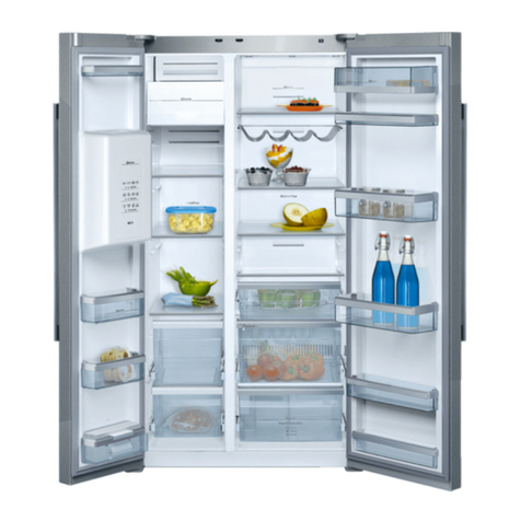
NEFF K5930D1GB Setup guide

R
R
RE
E
EP
P
PA
A
AI
IIR
R
R
I
IIN
N
NS
S
ST
T
TR
R
RU
U
UC
C
CT
T
TI
IIO
O
ON
N
N
X-Cool Side by Side Refrigerator
523_58300000186266_ARA_EN_F –01.03.18 Seite 1 von 49
1SAFETY ........................................................3
1.1 Safety instructions ............................................................... 3
1.2 Repair instructions...............................................................3
2COMPONENTS.............................................4
2.1 Overall view...........................................................................4
2.2 Compressor room................................................................. 4
2.3 Power Control Boards (PCB)...............................................5
2.4 Temperature sensor.............................................................5
2.5 Fans .......................................................................................6
2.6 Motorised TCD flaps.............................................................7
2.7 Heaters...................................................................................7
2.8 Humidity room ......................................................................7
2.9 Ice maker...............................................................................8
2.10 Ice/water dispenser ............................................................10
2.11 Water valve and water tank................................................11
2.12 Switches.............................................................................. 12
3FUNCTIONS................................................13
3.1 Cooling system................................................................... 13
3.2 Water circuit........................................................................ 13
3.3 Electronic control...............................................................14
3.4 Alarm function ....................................................................15
3.5 Fans .....................................................................................16
3.6 Defrosting mode.................................................................16
4REPAIR.......................................................18
4.1 Notes ....................................................................................18
4.2 Removing the Switches......................................................18
4.3 Removing the PCBs............................................................18
4.4 Access to the evaporators..................................................19
4.5 Sealing the TCD inlet flap...................................................22
4.6 Sealing and checking the evaporator fan..........................24
4.7 Removing the compressor room cover.............................24
4.8 Removing the Inverter box .................................................25
4.9 Removing the compressor.................................................25
4.10 Removing the Ice maker .....................................................25
4.11 Exchanging the water filter.................................................28
4.12 Removing the water valves ................................................28
4.13 Water valve repair kit [705920]...........................................28
4.14 Exchanging the ring connectors at the valves .................29
4.15 Exchanging the water tubes...............................................29
4.16 Leakage at the water dispenser .........................................30
4.17 Exchanging the door closer base......................................30
4.18 Removing the door in door option (DiD) ...........................32
4.19 Adjusting the appliance......................................................33
5FAULT DIAGNOSIS....................................36
5.1 Display functionality ...........................................................36
5.2 Light......................................................................................36
5.3 No Power..............................................................................37

R
R
RE
E
EP
P
PA
A
AI
IIR
R
R
I
IIN
N
NS
S
ST
T
TR
R
RU
U
UC
C
CT
T
TI
IIO
O
ON
N
N
X-Cool Side by Side Refrigerator
523_58300000186266_ARA_EN_F –01.03.2018 Site 2 of 49
5.4 Appliance does not start.................................................... 38
5.5 RC/FC not cold enough......................................................38
5.6 TCD not cold enough..........................................................39
5.7 Snow and ice in FC.............................................................39
5.8 Dew water............................................................................39
5.9 Noise.................................................................................... 40
5.10 Appliance shakes ...............................................................41
5.11 Doors are not at the same level.........................................41
5.12 Doors not parallel ...............................................................41
5.13 Flurida & EMZ......................................................................42
6TECHNICAL SPECIFICATIONS .................47
6.1 Dimensions .........................................................................47
6.2 Components........................................................................47
6.3 NTC sensor..........................................................................49

R
R
RE
E
EP
P
PA
A
AI
IIR
R
R
I
IIN
N
NS
S
ST
T
TR
R
RU
U
UC
C
CT
T
TI
IIO
O
ON
N
N
X-Cool Side by Side Refrigerator
523_58300000186266_ARA_EN_F –01.03.2018 Site 3 of 49
1 SAFETY
1.1 Safety instructions
Danger!
Repairs may be carried out only by customer service engineer,
trained by the manufacturer.
Improper repairs may lead to danger and damage for the user.
The housing or frame may be live in case of error.
Do not touch components in the appliance; even the modules can
be live.
Before commencing repairs, always disconnect the appliance from
the power supply.
If tests under tension are required, always use a residual-current-
operated circuit-breaker!
The protective conductor connection must not exceed the
standardised values. This is essential for personal safety and
appliance function.
When repairs are complete, conduct a test in accordance with VDE
0701 or the corresponding national regulations as well as a
performance test.
Conduct a leak and performance test on the refrigeration circuit.
1.2 Repair instructions
Caution!
Comply with ESD information.
Never attempt repairs by randomly replacing components.
Always proceed systematically and comply with the technical
documentation for the appliance.
As a rule, printed-circuit boards are not repaired but are completely
replaced by original spare parts. Exceptions are documented
separately.
When handling refrigerants, wear goggles and protective gloves. If
refrigerant splashes into eyes, rinse with plenty of water. EU and
CN models are using R600a, US models are using R134a.
Do not solder pipe connections in refrigeration. Use Lokring
connections.

R
R
RE
E
EP
P
PA
A
AI
IIR
R
R
I
IIN
N
NS
S
ST
T
TR
R
RU
U
UC
C
CT
T
TI
IIO
O
ON
N
N
X-Cool Side by Side Refrigerator
523_58300000186266_ARA_EN_F –01.03.2018 Site 4 of 49
2 COMPONENTS
2.1 Overall view
2.2 Compressor room
①EMC filter
②Inverter box
③solenoid valve
④Compressor
⑤Condenser fan
⑥Condenser
⑦Power module
⑧Water valve
①
②
③
④
⑤
⑥
⑦
⑧

R
R
RE
E
EP
P
PA
A
AI
IIR
R
R
I
IIN
N
NS
S
ST
T
TR
R
RU
U
UC
C
CT
T
TI
IIO
O
ON
N
N
X-Cool Side by Side Refrigerator
523_58300000186266_ARA_EN_F –01.03.2018 Site 5 of 49
2.3 Power Control Boards (PCB)
2.3.1 Ice water dispenser and main control module (CM)
2.3.2 Display and operation module (DOM)
2.3.3 Power Module (IWD PM)
2.3.4 Power Module (IWS PM)
2.4

R
R
RE
E
EP
P
PA
A
AI
IIR
R
R
I
IIN
N
NS
S
ST
T
TR
R
RU
U
UC
C
CT
T
TI
IIO
O
ON
N
N
X-Cool Side by Side Refrigerator
523_58300000186266_ARA_EN_F –01.03.2018 Site 6 of 49
Temperature sensor
2.5 Fans
①
②
③
①
②
①Refrigerator sensor
②Freezer sensor
③TCD sensor
①Freezer compartment (FC) fan
②Refrigerator compartment (RC)
fan

R
R
RE
E
EP
P
PA
A
AI
IIR
R
R
I
IIN
N
NS
S
ST
T
TR
R
RU
U
UC
C
CT
T
TI
IIO
O
ON
N
N
X-Cool Side by Side Refrigerator
523_58300000186266_ARA_EN_F –01.03.2018 Site 7 of 49
2.6 Motorised TCD flaps
2.7 Heaters
There are two kind of heaters in this appliance:
Drain heater
Defrosting heaters
①Evaporator sensor
②Thermal fuse
2.8 Humidity room
The washable humidity filter keeps the humidity of the food.
②
①Air inlet flap with
heater
②Air oulet flap
①
②
①

R
R
RE
E
EP
P
PA
A
AI
IIR
R
R
I
IIN
N
NS
S
ST
T
TR
R
RU
U
UC
C
CT
T
TI
IIO
O
ON
N
N
X-Cool Side by Side Refrigerator
523_58300000186266_ARA_EN_F –01.03.2018 Site 8 of 49
2.9 Ice maker
There are two different icemakers for SbS refrigerators:
- Flurida ice maker for IWD appliances
- EMZ ice maker for IWS appliances
The main difference between these icemaker concern the water inlet
and the dispenser system. The specific differences are described in
the following chapter.

R
R
RE
E
EP
P
PA
A
AI
IIR
R
R
I
IIN
N
NS
S
ST
T
TR
R
RU
U
UC
C
CT
T
TI
IIO
O
ON
N
N
X-Cool Side by Side Refrigerator
523_58300000186266_ARA_EN_F –01.03.2018 Site 9 of 49
1. Flurida ice maker
①Horizontal switch
②ON/OFF switch
③ON/OFF lever
④Ice sensor
2. EMZ ice maker
Water inlet
with heater
①
②
③
④
Test switch
Water inlet
LED light

R
R
RE
E
EP
P
PA
A
AI
IIR
R
R
I
IIN
N
NS
S
ST
T
TR
R
RU
U
UC
C
CT
T
TI
IIO
O
ON
N
N
X-Cool Side by Side Refrigerator
523_58300000186266_ARA_EN_F –01.03.2018 Site 10 of 49
2.10 Ice/water dispenser
1)Flurida
①Water outlet nozzle
②Ice outlet flap (with heater inside)
③Ice outlet flap motor
④housing heater switch
Connectors:
①Flap heater signal (yellow/yellow –white/white)
②Flap motor signal (red/black –red/white)
③Flap position feedback signal (red/black –blue/gray)
④LED Light (red/black –red/black)
NOTE: Be careful with connectors ①and ②. The male and
female plugs could be mismatched. The flap will not stop running.
2)EMZ
Connectors:
①Dispenser LED lights signal
②Flap motor +flap heater+ Flap position feedback signal
③DOM signal
Components
④water outlet nozzle
⑤Ice outlet flap
⑥Ice outlet flap motor
Note:
Please also hold the glass by one hand when getting the crushed ice
cube from the dispenser,otherwise some of the ice cube may fall out
of the glass to the ground.
①
②
③
①
②
③
④
④

R
R
RE
E
EP
P
PA
A
AI
IIR
R
R
I
IIN
N
NS
S
ST
T
TR
R
RU
U
UC
C
CT
T
TI
IIO
O
ON
N
N
X-Cool Side by Side Refrigerator
523_58300000186266_ARA_EN_F –01.03.2018 Site 11 of 49
2.11 Water valve and water tank
Water tank
Water valves:
One inlet, two outlets
One inlet, one outlet
Water filters or Bypass-Filter:
Screen filter (with PP filtration inside) :
Mat-Nr. 00643019
Ultraclarity filter (with carbon block inside) :
Mat-Nr. 00499850
Bypass-Filter:
Mat.-No. 00635026

R
R
RE
E
EP
P
PA
A
AI
IIR
R
R
I
IIN
N
NS
S
ST
T
TR
R
RU
U
UC
C
CT
T
TI
IIO
O
ON
N
N
X-Cool Side by Side Refrigerator
523_58300000186266_ARA_EN_F –01.03.2018 Site 12 of 49
2.12 Switches
①FC light switch
②RC light switch
③Main switch
Light temperature limit switch
NOTE: When the temperature near the light is too high, this auto-
switch will turn off the light to protect it. When the temperature cools
down, this switch will turn the light on again.
Max. temperature: 150 °C
OFF temperature: (60±5) °C
ON temperature: (35±15) °C
housing heater switch(Only for Flurida appliance)
In order to avoid dew water at the dispenser, there is heater in the
IWD housing. The heater of some VIBs was control by control module,
and some VIBs was controlled by heater switch.
If there are dew water at the dispenser, please turn the heater on via
this switch.
①
②
③

R
R
RE
E
EP
P
PA
A
AI
IIR
R
R
I
IIN
N
NS
S
ST
T
TR
R
RU
U
UC
C
CT
T
TI
IIO
O
ON
N
N
X-Cool Side by Side Refrigerator
523_58300000186266_ARA_EN_F –01.03.2018 Site 13 of 49
3 FUNCTIONS
3.1 Cooling system
The appliance and has two separate cooling circuits, one for the
freezer compartment (FC) and one for the refrigerator compartment
(RC). Two evaporators (①FC/ ②RC) share one compressor (④)
and a solenoid valve(③) regulates the refrigerant supply. When both
compartments need refrigerant, the FC has priority over the RC.
If the appliance is equipped with an inverter compressor, the
refrigerant goes through the condenser first then the FC heating tube.
If the appliance is equipped with a normal compressor, the refrigerant
goes through the FC heating tube then the condenser.
3.2 Water circuit
When water is requested by either the water dispenser (③) or the ice
maker (①)it first runs from the water inlet (⑤) through water tubes to
the water filter (②), located in the RC, and then is directed to a water
valve system. The water valve (④) distributes the water.
NOTE: The water tubes, which are connected to the Dispenser
and Ice maker are ¼” big. All other tubes are 5/16” big.
①
②
④
③
①Ice maker
②water filter
③Dispenser
④Water valve
⑤Water inlet
⑥Water tank
①
②
③
④
⑤
⑥

R
R
RE
E
EP
P
PA
A
AI
IIR
R
R
I
IIN
N
NS
S
ST
T
TR
R
RU
U
UC
C
CT
T
TI
IIO
O
ON
N
N
X-Cool Side by Side Refrigerator
523_58300000186266_ARA_EN_F –01.03.2018 Site 14 of 49
3.2.1 Water flow for Dispenser
From the water valve (④), the water flows into a water tank with a 1-
liter capacity (⑥). The water is dispensed through the Dispenser (③).
NOTE: The freshness of the water may be reduced, if no water
has been dispensed for a longer time.
3.2.2 Water flow for Ice maker
From the water valve (④), the water goes through water tubes in the
rear of the freezer and is then led to the ice maker water inlet. From
there it flows into the ice tray of the ice maker (①).
3.3 Electronic control
This appliance is equipped with 5 NTC sensors, which control the
temperature of FC, RC, TCD, FC-evaporator and RC-evaporator
respectively.
3.3.1 FC/RC Running and temperature control
FC temperature range: -16 °C to -26 °C / 7 °F to -15 °F
RC temperature range: 2°C to 8°C / 35°C to 46°C
When the temperature of FC or RC rises, the control module connects
the solenoid valve (opens to FC evaporator or RC evaporator), FC-fan
or RC-fan, compressor, the FC or RC is under cooling. Once the
selected temperature is reached, the control module disconnects the
fan and also closes the solenoid valve.
RC/ FC
ON: T ≥Tsetpoint + Toffset (2K) + Thysteresis (2.5 K)
OFF: T≤Tsetpoint + Toffset (2K) + Thysteresis (2.5 K)
NOTE: When the relevant compartment door is open, the
compressor is still functioning but the relevant fan stops.

R
R
RE
E
EP
P
PA
A
AI
IIR
R
R
I
IIN
N
NS
S
ST
T
TR
R
RU
U
UC
C
CT
T
TI
IIO
O
ON
N
N
X-Cool Side by Side Refrigerator
523_58300000186266_ARA_EN_F –01.03.2018 Site 15 of 49
3.3.2 TCD airflow and temperature control
The fan of the TCD sucks in the cold air of the evaporator via the TCD
flap (①). The air is blown into the TCD (②)and then exits the TCD
again through the air outlet flap (③). The fan and the flaps are
controlled by the control module. Once the selected temperature is
reached, the fan stays off and the flaps are closed, but heater runs
intermittently.
The TCD can only be set at either 0°C, 2°C or 4°C / 32°F, 35.5°F or
39°Fvia the display panel.
3.4 Alarm function
If an alarm is triggered, an audible warning signal sounds and an
information window is displayed.
►Tap OK to switch off the audible warning signal.
An alarm may be triggered in the following cases:
Door alarm
The door alarm is triggered, when one of the appliance doors remains
open for longer than 30s. The alarm stops when the door is closed
again.
Temperature alarm
The temperature alarm is triggered, when a compartment becomes
too warm and the food is endangered.
The information window displays the too warm compartment.
Without endangering the frozen food, the temperature alarm is
triggered in this cases:
First use of the appliance.
Putting large quantities of food in the freezer compartment
②
③
TCD ON:
Fan on (4min)
Fan off (2min)
Flaps open
Flap heaters off
TCD OFF:
Fan off
Flaps closed
Flap heaters on (2min)
Flap heaters off (4 min)
①

R
R
RE
E
EP
P
PA
A
AI
IIR
R
R
I
IIN
N
NS
S
ST
T
TR
R
RU
U
UC
C
CT
T
TI
IIO
O
ON
N
N
X-Cool Side by Side Refrigerator
523_58300000186266_ARA_EN_F –01.03.2018 Site 16 of 49
3.5 Fans
3.5.1 Compartment fans
General
Fan is switched ON
After the door is open more than 10min
After the door is closed, ON for 30s
When the relevant compartment is in chilling
Fan is switched OFF
When the door is open
Speed
Fan speed is controlled by the ambient temperature, measured by
ambient sensor on the DoM.
RC
RC is not in chilling
The RC fan is switched ON for 2min and OFF for 10min
Input voltage of RC fan
Increases 1V after the first 30min and increases another 0.5V after
the second 60min.
FC
FC is not in chilling
The FC fan is switched OFF.
FC fan speed
Increases 300rpm after the first 120min and increases another
200rpm after the second 60min.
3.5.2 Condenser fan
The fan will switch ON 1 min later after the compressor starts to run.
When the ambient temperature is below 18°C/64.5°F, the fan is
switched ON for 3min and OFF for 3min.
Initial speed of the fan is decided by ambient temperature.
3.6 Defrosting mode
These factors affect the start of defrosting:
the last defrosting period
appliance running time
compressor running time
door openings
After the defrosting process the appliance switches to normal
operation.

R
R
RE
E
EP
P
PA
A
AI
IIR
R
R
I
IIN
N
NS
S
ST
T
TR
R
RU
U
UC
C
CT
T
TI
IIO
O
ON
N
N
X-Cool Side by Side Refrigerator
523_58300000186266_ARA_EN_F –01.03.2018 Site 17 of 49
3.6.1 FC
The FC defrost phase will be triggered at the earliest after 6h and at
the latest after 73h of operating time.
3.6.2 RC
The RC defrost phase will be triggered at the earliest after 8h and at
the latest after 73h of operating time.
All components
switch OFF for 5min.
The defrosting heater
runs
for max. 45 min.
OR
until evaporator reaches
6°C
The drain heater runs
for 6min.
RC fan switches
ON for 10min.
All components
switch OFF for
2min.
The defrosting
heater runs
for max. 30 min.
OR
until evaporator
reaches 8°C
All components
switch OFF for
3min.

R
R
RE
E
EP
P
PA
A
AI
IIR
R
R
I
IIN
N
NS
S
ST
T
TR
R
RU
U
UC
C
CT
T
TI
IIO
O
ON
N
N
X-Cool Side by Side Refrigerator
523_58300000186266_ARA_EN_F –01.03.2018 Site 18 of 49
4 REPAIR
4.1 Notes
NOTE: In the following chapters the removing of the components
is described. Their installation is in reverse sequence to that.
Required tools:
Screwdriver Torx
Screwdriver Phillips
Pincer
wrench
4.2 Removing the Switches
►Ease the covers of the switches with a screwdriver.
►Remove the covers with a pincer.
►Take out the switches with a pincer.
4.3 Removing the PCBs
4.3.1 IWD, CM
►Unscrew the covers of the PCBs with a screwdriver.
►Take out the PCBs.
4.3.2 DOM
►Remove the display module by pressing two notches under the
dispenser flap support.
4.3.3 PM
Prerequisite: the compressor room cover and the water valve are
removed.
►Unscrew the two screws with
a hexagon wrench.
►Pull out the power module.

R
R
RE
E
EP
P
PA
A
AI
IIR
R
R
I
IIN
N
NS
S
ST
T
TR
R
RU
U
UC
C
CT
T
TI
IIO
O
ON
N
N
X-Cool Side by Side Refrigerator
523_58300000186266_ARA_EN_F –01.03.2018 Site 19 of 49
4.4 Access to the evaporators
4.4.1 FC
►Remove the two screw
covers.
►Unscrew the lower airflow
cover.
►Remove the lower airflow
cover.
NOTE: consider the two
hooks!
►Unscrew the evaporator
cover.
►Lift up the upper airflow
cover.

R
R
RE
E
EP
P
PA
A
AI
IIR
R
R
I
IIN
N
NS
S
ST
T
TR
R
RU
U
UC
C
CT
T
TI
IIO
O
ON
N
N
X-Cool Side by Side Refrigerator
523_58300000186266_ARA_EN_F –01.03.2018 Site 20 of 49
►Release two hooks from the
fan housing.
►Remove the evaporator
cover.
NOTE: consider the rest 10
hooks, there are marks at the
front side of the evaporator
cover.
4.4.2 RC
►Remove the excenter shelf
with a screwdriver.
►Take down two holders
►Remove the glass shelf.
►Remove the metall bar.
►Remove the cover of the
water filters.
►Unscrew the cover of the
water filter.
Table of contents
Other NEFF Refrigerator manuals

NEFF
NEFF K5660X0 User manual

NEFF
NEFF K811 series User manual

NEFF
NEFF KI181 Series User manual

NEFF
NEFF KI1813FE0G User manual

NEFF
NEFF KI181 Series User manual

NEFF
NEFF K5714 Series User manual

NEFF
NEFF K7791X0 User manual

NEFF
NEFF KI852 Series User manual

NEFF
NEFF KI8816DE0G User manual

NEFF
NEFF K431 User manual

NEFF
NEFF KUR Series User manual

NEFF
NEFF KI242 Series User manual

NEFF
NEFF KI151 User manual

NEFF
NEFF K81 Series User manual

NEFF
NEFF K431 User manual

NEFF
NEFF KI12 Series User manual

NEFF
NEFF KI887 Series User manual

NEFF
NEFF KI1413FF0G/01 User manual

NEFF
NEFF K4254X7GB User manual

NEFF
NEFF KA90N Series Operation manual