Neilsen CT0866 User manual

SAV
E
READ ALL
Cannon
T
Address:
600
M
OR
I
E
THESE IN
PRECAUT
T
ools Limited
20 Station Roa
M
L SPR
A
I
GINAL INS
STRUCTIO
ONS AND I
d, Rowley Regi
A
Y GUN
TRUCTION
NS
A
ND P
R
NSTRUCTI
O
s, West Midlan
d
CT0866
S
R
ECAUTIO
N
O
NS BEFO
d
s, B65 0JU.U.
K
N
S.
RE USE.
K
.

2
EC DECLARATION OF CONFORMITY
We CANNON TOOLS LTD
20 Station road, Rowley Regis, West Midlands,B65 0JU.U.K.
Declare that the following machine complies with the appropriate basic safety and
health requirements of the EC Directive based on its design and type, as brought
into circulation by us.
In case of alteration of the machine, not agreed upon by us, this declaration will
lose its validity.
Product description: SPRAY GUN
Model: CT0866
Applicable EC Directives:
EC Machinery Directive 2006/42/EC
Harmonized standards
EN ISO 12100, EN 1953
20 Station Road, Rowley Regis, West Midlands, B65 0JU.U.K.
Mr. Gurcharan Tony Singh Sanghera
Managing Director
CANNON TOOLS LTD
2017-12-26

3
1. SAFETY WARNINGS
SYMBOLS
In this manual and/or on the machine the following symbols are used:
zLocate the spray gun in a suitable work area. Keep this area clean and tidy and free from
unrelated materials. Ensure that there is adequate ventilation and lighting.
zFamiliarise yourself with the application, limitations and potential hazards peculiar to the
spray gun.
zWARNING! Disconnect the spray gun from the air supply before changing accessories,
servicing or performing any maintenance.
zMaintain the spray gun in good condition (use an authorised service agent).
zReplace or repair damaged parts. Use authorised parts only. Unauthorised parts may be
dangerous and will invalidate the warranty.
zKeep the spray gun clean for best and safest performance.
zEnsure that the compressed air system can supply the spray gun air consumption for the
model to be used.
zWear approved safety respiratory protection and safety eye goggles.
zIf spraying isocyanate based finisher, wear approved respirator/clean air breathing
apparatus and cover exposed skin with latex gloves and an impervious hooded coverall.
zRemove ill-fitting clothing. Remove ties, watches, rings and other loose jewellery and tie
back long hair.
zKeep children and unauthorised persons away from the work area.
zWhen not in use, ensure that the air supply is turned off.
zAvoid unintentional operation of the spray gun.
zWhen not in use, disconnect the spray gun from the air supply, clean thoroughly and store
safely.
Denotes risk of personal injury, loss of life or damage to the tool
in case of non-observance of the instructions in this manual.
Wear hearing protection.
Wear safety goggles.
Contact with or inhalation of dust coming free during use (e.g.
lead-painted surfaces, wood and metal) can endanger your
health and the health of bystanders. Always wear appropriate
protective equipment, such as a dust mask. Always use proper
dust extraction during use.
Wear gloves.

4
zDO NOT point spray gun at yourself, other persons or animals.
zDO NOT direct air from the air hose at yourself, other persons or animals.
zDO NOT carry the spray gun by the hose, or yank the hose from the air supply.
zDO NOT exceed the working pressure of 50psi.
zDO NOT use the spray gun for any purpose other than that for which it is designed.
zDO NOT allow untrained persons to operate the spray gun.
zDO NOT get the spray gun wet or use in damp or wet locations or in areas where there is
condensation.
zDO NOT operate the spray gun if any parts are missing or damaged as this may cause
failure and/or personal injury.
zWARNING! The warnings, cautions and instructions in this manual cannot cover all possible
conditions and situations that may occur. It must be understood by the operator that
common sense and caution are factors which cannot be built into this product, but must be
applied by the operator
2. SPECIFICATION
Air Consumption: 170-310 l/min
Required Pressure: 43 - 50 Psi
Nozzle Size 1.4mm
Air Inlet: 1/4"
Cup capacity: 600ml
3. AIR SUPPLY
FAILING TO COMPLY WITH THESE INSTRUCTIONS WILL RESULT IN YOUR AIR TOOL
FAILING EARLY; THIS WILL NOT BE COVERED BY THE GUARANTEE.
To get the best from your spray gun you will need to connect it to a compressor easily able of
supplying the large amount of air that it this type of product demands.
To make sure enough air reaches the gun, it should be supplied using a 3/8" diameter line or
greater. If you are using an air tool on a hose over 25ft. long it is advisable to increase the bore
of the hose to the next larger size available.
This air tool operates at a maximum pressure of 30psi or 50psi depending on model and must
be controlled via a joint pressure regulator/water separator unit which with proper maintenance
will ensure a constant supply of dry air at all times. Water from condensation can build up inside
the compressor tank and air lines: this will cause your equipment to rust if not properly dealt
with.
Always check the air line output operating pressure before connecting the spray gun.

5
4. ASSEMBLY
Carefully remove everything from the packaging and compare it against the contents
list. If anything appears to be missing please contact the place of purchase.
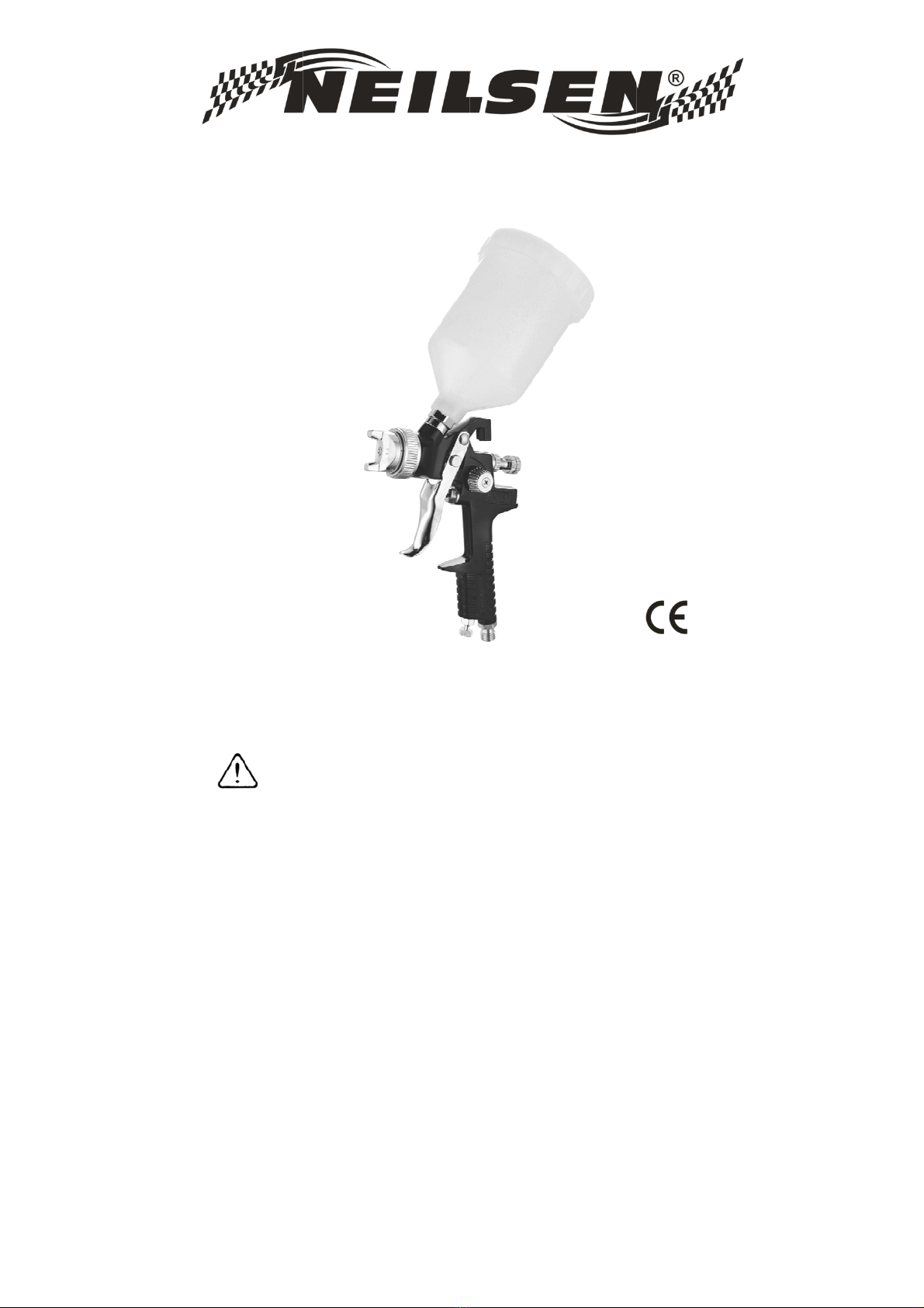
ATTACHING AN AIR LINE COUPLING (Fig.1):
After purchasing the spray gun and before initial use an
air line coupling must be fitted that is compatible with
your compressor's trailing hose.
1. Select a suitable 1/4” female thread air line coupling.
2. Wind a length of PTFE tape around the thread.
3. Screw the coupling on to the spray gun.
4. The connection must be firm for an airtight union.
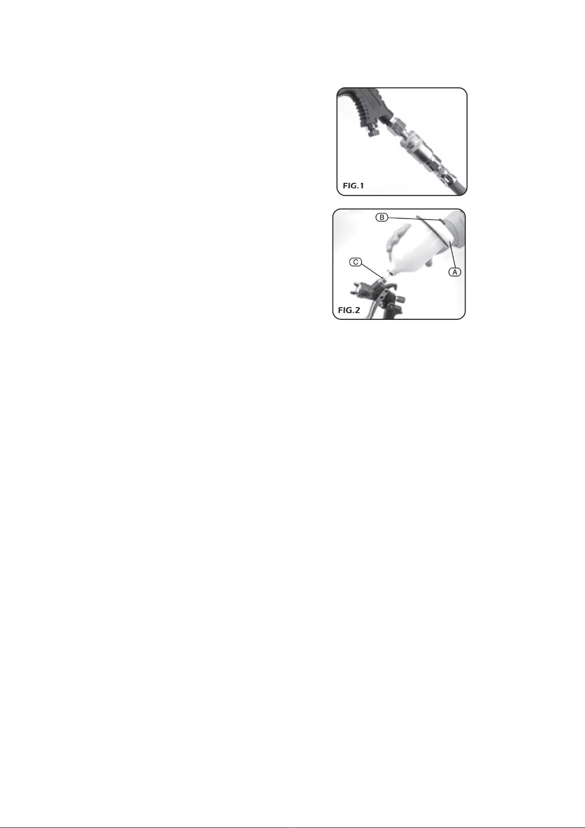
CONNECTING THE PAINT POT (Fig.2):
After purchasing the spray gun and before initial use,
wash the spray gun through to clear the air and paint
channels of any debris or dust.
1. Turn the paint pot lid (A) anticlockwise to remove it.
2. Fill the paint pot with material.
3. Carefully refit the pot lid (A). Turn the lid
anticlockwise a little to seat it correctly on the
thread, before turning it clockwise to tighten.
4. Make sure the bleed screw (B) is screwed in to
prevent paint loss.
5. Screw the paint pot assembly into the top of the
spray gun connector (C). Turn the pot clockwise
until tight.
5. OPERATION
5.1 Putting into operation
Before putting into operation,and especially after any repair work. check to see that all nuts and
bolts are tight. Always disconnect the unit from the air supply before carrying out any repair
work.
a) Mount the nozzle set tightly Align the air nozzle so that the number stamped into it can be
read from the front the right way round.
b) Blow out the air hose before attaching it to the air connection (1/4").(Air hose
pressure-resistant up to min.10 bar and) solvent-resistant. Total electric resistance: less than
100 million Ohm;)
c) The paint spray gun has been treated with an anticorrosive agent before leaving the factory
and must therefore get flushed out thoroughly with thinner before use.
5.2 Adjusting the volume of air using the compressed-air micrometer.
The air supply can be regulated extremely fine to suit all potential conditions. Micrometer in

6
vertical position (parallel to gun body)=maximum atomization. Micrometer in horizontal position
(across gun body)=minimum atomization(for blending, etc.) During operation, never remove
hollow (item 12) by using the small hollow key in order to remove the micrometer.
5.3 Reduction of the material volume
The volume of material flowing from the nozzle and thus the needle stroke can be reduced
steplessly by screwing in the material-volume regulation screw.
5.4. Changing the nozzle set
Always change the complete nozzle set whenever changing nozzle size. These components,
that consist of air cap, fluid nozzle and paint needle, are supplied as a complete set. Insert
paint nozzle before paint needle.
5. 5 Exchanging the air piston and air piston packing
To replace the air piston remove the hollow screw and detach the air micrometer. Pull out
spring and air piston Exchange the air piston Unscrew stuffing box screw and remove the old
packing. Now insert new Packing with flat end first and gently tighten stuffing box screw
towards packing.
6 CLEANING AND MAINTENANCE
a) Flush the material-conveying parts of the gun thoroughly with thinner.
b) Clean the air nozzle with a paint brush or brush. Do not immerse the nozzle in thinner.
c) Under no circumstances try to clean clogged orifices using an unsuitable tool, since the
slightest amount of damage

7
7. TROUBLESHOOTING
Problem Possible Causes Suggested Remedy
1 .Gun leaks from fluid tip 1.Foreign substances between
fluid tip and needle prevent sealing 1 Clean fluid needle an fluid nozzle in
thinner or use new set nozzle
2.Paint merges from fluid
needle-needle sealing 2.Self tensioning needle sealing
damaged or lost 2.Replace needle sealing
3.Spray pattern in
Sickle shape 3. Horn air holes or air circuit
clogged. 3.Soak in thinner, afterwards clean with
the nozzle-cleaning needle.
4.Drop like or oval shaped
pattern
4.Dirt on fluid pin tip or air outlet 4.Turn air nozzle by 180 degrees, if
defective pattern remains, clean fluid tip pin
and air circuit
5.Paint spray flutters
5.Too little material in cup, fluid
nozzle not tight self-adjusting,
needle sealing damaged,
nozzle set dirty or damaged
5.Refill material, tighten parts, if necessary
clean or replace parts
6.Material bubbles or boils in
paint cup
6.Atomization air flows through the
paint channel to the cup. The paint
nozzle is not sufficiently
tightened. Air nozzle is not
completely screwed on, the air net
clogged and the seat is defective
or nozzle inserts damaged.
6.Tighten pants accordingly. clean or
replace.
NOTE: Any adjustments made to remedy a problem will alter the original test pattern results. Slight rebalancing
may be necessary.
8. DISPOSAL
At the end of the product's working life, or when it can no longer be repaired, ensure that it
is disposed of according to national regulations.
In all circumstances:
Do not abandon in the environment.
Always read the literature supplied with the paint to ensure it is compatible with the equipment
and any other paint material that you intend using.

8
NO DESCRIPTION NO DESCRIPTION
1 Air nozzle with brass cap 19 Pattern adjustment stem
2 Fluid nozzle 20 Control knob
3 Air diversion ring 21 nut
4 Piston pad 22 Trigger bolt
5 compression screw 23 Locking plate
6 Compression spring for needle seal 24 Bolt
7 Sealing for air piston 25 Trigger sleeve
8 Gun body 26 Paint connection
9 Fluid control knob 27 Filter net
10 Spring for air piston 28 Plastic cup
11 Screw nut 29 Cover
12 Fluid control knob 30 Non-drip device
13 Stuffing box for air piston 31 Air Adjust Valve Ass'y
14 Packing for air piston 32 Air connection piece R1/4"
15 Air piston complete 33 Normal Cleaning brush
16 Piston ring 34 Hexagonal socket spanner
17 Air piston complete 35 Spanner
18 Spring for air piston

9
CANNON TOOLS LTD
Add: 20 station road, Rowley Regis, west midlands,B65 0JU.U.K.
Made in China
Table of contents
Other Neilsen Paint Sprayer manuals