nekos ALi SW User manual
4420039 – Rev. 1807
ALì SW
INSTRUCTION MANUAL
ELECTRICAL FEEDER
Electrical feeding 24V (stabilized)
NEKOS S.r.l. - Via Capitoni, 7/5 - 36064 Mason Vicentino (VI) – ITALY
EN
2
USER INSTRUCTIONS
CAUTION. Carefully observe all the following installation
instructions to ensure personal safety.
The device is not intended for use by persons (including
children) with reduced physical, sensory or mental capabilities,
or lacking experience and knowledge. Do not allow children to
play with the fixed controls and keep any remote-control units
out of their reach.
Have installation checks performed periodically by qualified
personnel from a service centre authorised by the manufacturer.
Do not use if repair or adjustment is required.
CAUTION: if the power cable is damaged, it must be replaced by
qualified personnel from a service centre authorised by the
manufacturer.
CAUTION. Disconnect the power supply during cleaning or
maintenance operations. Do not use solvents or jets of water to
wash the appliance; the appliance should not be submerged in
water.
In the event of fault or malfunction, switch off the device at the
main switch. All repairs and adjustments (e.g. setting the stroke)
must only be performed by qualified personnel from a service
centre authorised by the manufacturer.
Always request exclusive use of original spare parts. Failure to
respect this condition could compromise safety and invalidate
the benefits contained in the warranty for the appliance. In the
event of any problems or queries, consult your agent or contact
the manufacturer directly.
The A-weighted sound pressure level is less than 70dB(A).
Carefully preserve these instructions after installation.
3
INSTALLER INSTRUCTIONS
nekos products have been manufactured in accordance with safety standards and
conforms to the stipulations of current standards in force.
When correctly assembled, installed and used according to the present instructions,
they will not generate any danger for persons, animals or items.
Symbols used in the manual
DANGER This indication draw the attention about potential dangers for
safety and health of peoples and animals.
CONTENTS
1. Safety indications .......................................................................... 4
1.1. General notes ............................................................................ 4
1.2. Notes for installer and user ....................................................... 4
2. Accessories .................................................................................. 5
3. Electrical supply ........................................................................... 5
4. Assembly and electrical connection .............................................. 6
4.1. Requirements and checks ......................................................... 6
4.2. Electrical connection to grid ....................................................... 6
5. Technical data ............................................................................... 7
6. Label and data markings ............................................................... 7
7. Function of touch-switch control .................................................... 8
8. Motor control with traditional button ............................................... 8
9. Troubleshooting ............................................................................... 9
10. Environmental protection ................................................................. 9
11. Warranty ........................................................................................ 10
12. Declaration of conformity ............................................................... 11
4
1. SAFETY INDICATIONS
1.1. General notes
ATTENTION: Please read the following safety indications carefully
before attempting installation of this appliance. These indications
will help you to avoid contact with electrical current, injury and
other accidents. Please keep this manual for future consultation.
The manufacturer can not be held responsible for any damages to
people, animals or things, due to inobservance of basic security
rules described in this manual.
Any use of the actuator for applications other than those indicated
must previously be authorized by the manufacturer upon technical
verification of the application
1.2. Notes for installer and user
The ALì SW electrical feeder has been designed exclusively for feeding
electrical motors functioning in low tension 24V .
The device must only be installed by competent and qualified technical
staff.
After removing all packaging, please verify that all parts of the
appliance are present.
Any plastic bags, polystyrene, or small metallic parts such as nails,
clips, etc. must be stored out of the reach of children as they constitute
potential sources of danger.
The appliance is not intended for use by people (including children)
whose physical, sensory and mental abilities are reduced, or in case of
lack of experience or knowledge; such persons must be supervised to
ensure that they do not play with the appliance.
Before connecting the appliance to the electricity supply, check that the
electricity supply in use has the same characteristics as those indicated
on the technical data label on the device.
This appliance is destined exclusively for the use for which it has been
designed and the manufacture cannot be held responsible for any
damages incurred by improper use.
Installation of the device must be carried out in accordance with the
instructions set out by the manufacturer. Failure to follow these
instructions could compromise safety.
5
Electricity supply installation must be carried out in accordance with
regulations in force.
To avoid danger of lesions or death due to electrical current, we
suggest to disconnect tension from the feeding line before doing any
cable or regulation operation.
To assure a good separation from the line, install a sectioning device
with differential protection of 30mA at the start of the electrical line.
Never clean the device with solvents or jets of water.
Before doing any cleaning or maintenance operation be sure of having
disconnected the device from the line. For more certainty we suggest to
disconnect electrical connections.
Eventual repairs must only be carried out by qualified staff at a service
centre authorized by the manufacturer.
Always require exclusive use of original spare parts. Failure to comply
with this stipulation could compromise safety and forfeit warranty
benefits for the device.
In the event of trouble or doubts, please refer to your trust retailer or
directly to the producer.
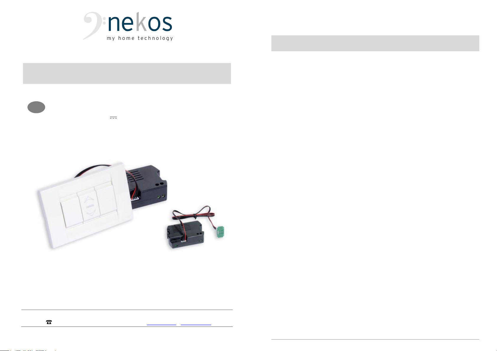
2. ACCESSORIES
The ALì SW power supply unit comes assembled in a box and ready for
connection. The appliance consists of:
Electrical power supply enclosed in plastic container.
200 mm connection cable. Also available in 800 mm length on request.
Touch-switch button on commercial cover with arrows indicating direction.
(Product is on VIMAR module IDEA series, but other types of models can
be supplied on request).
3 module support for insertion on boxing or externally (supplied only on
request).
External cover plate (supplied only on request).
Instructions manual.
3. ELECTRICITY SUPPLY
The ALì SW power supply is for connection to grids with alternate current from
100V~ to 240V~, 50÷60Hz.
This product has been designated as a Class II safety product.
6
4. ASSEMBLY AND ELECTRICAL CONNECTION
These indications are intended for the attention of technicians and specialized
personnel. Basic job and safety techniques are therefore not included.
4.1. Requirements and checks
All operations for preparation, assembly and electrical connection must be
performed by competent and specialised technical personnel to guarantee
optimal performance and good function of the appliance.
First check that the following basic conditions have been met:
Remove the unit from its packaging and visually check for any damage that
may have occurred during transport.
Unit performance must be sufficient to guarantee the energy required for
correct function of the motor in question, do not exceed the limits indicated
in the technical data table for the product (p. 7).
Attention: Make sure that output tension corresponds to that required for
function of the motor in question to avoid compromising good function.
Check that electrical wiring is appropriate and has the correct section
dimensions to comply with safety standards in force.
Check that the casing for the unit has been correctly fitted, is easily
accessible and does not impede the control action for the motor connected.
4.2. Electrical connection to grid
Remove the support plate and place to one side. Check the two fixing
screws are present. If not, use appropriately sized screws.
Remove the unit from the packaging box in preparation for connection. Do
not open the plastic container, connection can be performed externally.
Connect the two electrical grid wires to the terminals in the plastic box area
marked “100÷240VAC”. Do not connect the earth wire, the unit has double
Class II safety insulation.
Connect the two wires supplying power to the motor to the other terminal
board marked with “24VDC”.
Attention: terminals which have not been connected properly could
damage the appliance and compromise safety.
Check wires have been inserted completely into the terminal and ensure
screws have been appropriately tightened.
Remove any dust or residual waste created during connection from the
wall box (or other container) and check that the electrical wires can be
placed in position free of obstacles, crushing or damage.
Insert the unit into the wall box.
Check that the connectors for the cables between the unit and the touch-
switch have been inserted correctly. If cabling has been disconnected, take

7
care when inserting as the connection is polarised and there is only one
option for insertion of the connector.
Assemble the support with the two screws already inserted.
Re-assemble the plate by snapping into place.
Press the button to perform test controls with forward/reverse movement
and check for correct movement of the motor. If the motor turns in the
wrong direction, invert the position of the wires on the terminal board
marked with “24VDC”.
5. TECHNICAL DATA
MODEL ALì SW
Power supply voltage (UN) 100 ÷ 240V 50/60Hz
Current absorbed on empty (ISBY) 0.021A (@230V~)
Current absorbed when loaded (IN) 0.170A (@230V~)
Nominal output voltage (UO) 24V
Maximum output current (I0) 0.6A (@24V)
Electrical insulation Class II
Type of function S1 – CONTINUOUS
Working temperature from - 5 to +65 °C
Degree of protection for electrical devices IP20
Connection at input Screw terminals 2x2.5 mm²
Connection at output Screw terminals 2x1 mm²
Dimensions 87.5x55.5x27.5
Weight (unit only) 0.085 Kg
Any information reported in this table is not binding and may be susceptible to variations
without notice.
6. LABEL DATA AND MARKINGS
The ALì SW feeders have CE marking and comply with the Standards listed in
the Declaration of Conformity. They also come with a Declaration of
Incorporation, due to their classification by the Machinery Directive as “partly
completed machines”. Both declarations are included in the final pages of this
manual. The plate data is displayed on an adhesive label placed on the outside
of the casing, which must remain intact and visible. The main information it
displays includes: manufacturer's address, product name - model number,
technical characteristics, production date and serial number.
In the event of a complaint, please indicate the serial number (SN) displayed on
the label. An explanation of the symbols used on the label to abbreviate the
technical characteristics is given in the table in the chapter on “TECHNICAL
DATA”.
8
7. FUNCTION OF TOUCH-SWITCH CONTROL
The ALì SW unit has been provided with a control button / switch with touch-
switch function. To control the motor connected, touch or lightly brush (without
exerting any particular pressure) the area marked with the arrows on the cover:
upwards to open and downwards to close.
The touch-switch has two functions, and can be used as a button or as a switch
in the following two ways:
1. BUTTON mode.
Button function is activated by touching one of the two arrows. Control is
instant and terminates when there is no further contact with the button.
Stoppage is also immediate.
NOTE: when controlling certain motors (for example the MR28 reduction
motor) if the motor does not start immediately this is because the motor
itself has been programmed for delayed start.
2. SWITCH mode.
Switch function activates when one of the two arrows is clicked twice.
Double click has an interval of 0.1÷0.3 seconds between the two clicks, like
that used on the mouse on a computer.
Again, control is instant and the motor will only stop when:
The motor reaches an endpoint;
Either one of the two buttons is touched;
2 minutes after start function, as programmed by the manufacturer.
8. MOTOR CONTROL WITH TRADITIONAL BUTTON
The ALì SW usually runs with a touch-switch, but can also be controlled using a
conventional button / switch by making a slight and simple adjustment to the
cabling.
Using the cabling provided (for connection between the unit and the touch-
switch):
1. Cut the cable as close as possible to either one of the two connectors.
2. Separate out the four wires around 2 cm.
3. Strip the wires for connection to the button or switch.
4. Perform the electrical connection in accordance with the diagram below.
(The following diagram is an illustration of connection for the VIMAR button
series Idea, code 16145).

9
Test function to check connections are correct and that the motor turns in the
required direction. If this is not the case, invert the positions of wires 1 and 2.
9. TROUBLESHOOTING
Please consult the following table for any eventual problems with function
during installation or normal use:
Problem Possible cause Solution
Gear motor does not
function when
connected.
No electricity at feeder.
Cable not connected
or wire has not been
connected.
Feeder does not
provide required
tension (24V ).
Check the trip or
safety switch.
Check all electrical
connections on gear
motor.
Gear motor does not
function at required
speed.
Wrong feeder. Feeder
cannot provide
sufficient electricity.
Winding on the
transformer may be
broken.
Use more powerful
feeder.
Touch-switch does not
control movement.
One or both of the
connectors has not
been inserted correctly
Touch-switch board is
not touching cover
properly.
Remove connector(s)
and reconnect
Adjust board and fix
into position with hot
glue on component
side.
10. Environmental protection
All materials used in the manufacture of this appliance are recyclable.
10
We recommend that the device itself, and any accessories, packaging, etc. be
sent to a centre for ecological recycling as established from laws in force on
recycling.
The device is mainly made from the following materials: aluminium, zinc, iron,
plastic of various type, cuprum. Dispose materials in conformity with local
regulations about removal.
11. Certificate of guarantee
The manufacturer will guarantee good function of the appliance. The
manufacturer shall undertake to replace defective parts due to poor quality
materials or manufacturing defects in accordance with article 1490 of the Civil
Code.
The guarantee covers products and individual parts for 2 years from the date of
purchase. The latter is valid as long as the purchaser possesses proof of
purchase and completion of all agreed conditions of payment.
Guarantee of good function of appliances agreed by the manufacturer implies
that the latter undertakes to repair or replace free of charge and in the shortest
period possible any parts that break while under warranty.
The purchaser is not entitled to any reimbursement for eventual direct or
indirect damage or other expenses incurred. Attempt to repair by personnel
unauthorised by the manufacture shall render the warranty null and invalid.
The warranty does not cover fragile parts or parts subject to natural wear and
tear or corrosion, overload, however temporary etc. The manufacturer will
accept no responsibility for eventual damage incurred by erroneous assembly,
manoeuvre or insertion, excessive stress or inexpert use.
Repairs performed under guarantee are always "ex factory of the
manufacturer". Respective transport expenses (out/back) are the responsibility
of the purchaser.
Table of contents
Popular Power Supply manuals by other brands

Videx
Videx 520MR Installation instruction

Poppstar
Poppstar 1008821 Instructions for use

TDK-Lambda
TDK-Lambda LZS-A1000-3 Installation, operation and maintenance manual

TDK-Lambda
TDK-Lambda 500A instruction manual

Calira
Calira EVS 17/07-DS/IU operating instructions

Monacor
Monacor PS-12CCD instruction manual


