NELLCOR PURITAN BENNETT LP6 Plus User manual

LP6 Plus, LP10, and LP20
Volume Ventilators
Technical Manual
L-004238-001 Rev. B

LP6 Plus, LP10, and LP20 Technical Manual
November 2000
page ii
©Copyright 2000, Nellcor Puritan Bennett,Inc., 2800 Northwest Blvd., Minneapolis,
Minnesota 55441-2625 U.S.A. All rights reserved. No portion of this manual may be
copied, reproduced, or stored in any form without the express written permission of
Nellcor Puritan Bennett, Inc.
Nellcor Puritan Bennett is a registered trademark and A Breath of Fresh Air is a trade-
mark of Nellcor Puritan Bennett, Inc.
For more information: For information on our full line of medical equipment and related services, contact Nell-
cor Puritan Bennett directly. General: (800) 497-4979. Customer Service: (800) 497-
4968. Technical Service: (800) 497-3787.

LP6 Plus, LP10, and LP20 Technical Manual
November 2000
Page iii
Page iiiPage iii
Page iii
Contents
1 Introduction
1 Introduction1 Introduction
1 Introduction
Chapters
ChaptersChapters
Chapters - - - - - - - - - - - - - - - - - - - - - - - - - - - - - - - - - - - - - -
- - - - - - - - - - - - - - - - - - - - - - - - - - - - - - - - - - - - - -- - - - - - - - - - - - - - - - - - - - - - - - - - - - - - - - - - - - - -
- - - - - - - - - - - - - - - - - - - - - - - - - - - - - - - - - - - - - - 1-1
1-11-1
1-1
What’s New in this Revision
What’s New in this RevisionWhat’s New in this Revision
What’s New in this Revision - - - - - - - - - - - - - - - - - - - - - - - -
- - - - - - - - - - - - - - - - - - - - - - - -- - - - - - - - - - - - - - - - - - - - - - - -
- - - - - - - - - - - - - - - - - - - - - - - - 1-2
1-21-2
1-2
Conventions
ConventionsConventions
Conventions - - - - - - - - - - - - - - - - - - - - - - - - - - - - - - - - - - -
- - - - - - - - - - - - - - - - - - - - - - - - - - - - - - - - - - -- - - - - - - - - - - - - - - - - - - - - - - - - - - - - - - - - - -
- - - - - - - - - - - - - - - - - - - - - - - - - - - - - - - - - - - 1-2
1-21-2
1-2
2 Description
2 Description2 Description
2 Description
Components
ComponentsComponents
Components - - - - - - - - - - - - - - - - - - - - - - - - - - - - - - - - - - -
- - - - - - - - - - - - - - - - - - - - - - - - - - - - - - - - - - -- - - - - - - - - - - - - - - - - - - - - - - - - - - - - - - - - - -
- - - - - - - - - - - - - - - - - - - - - - - - - - - - - - - - - - - 2-2
2-22-2
2-2
Front Panel (LP20 shown) - - - - - - - - - - - - - - - - - - - - - - - - - - - - 2-2
Back Panel (LP20 shown) - - - - - - - - - - - - - - - - - - - - - - - - - - - - 2-4
Operating Controls
Operating ControlsOperating Controls
Operating Controls - - - - - - - - - - - - - - - - - - - - - - - - - - - - - -
- - - - - - - - - - - - - - - - - - - - - - - - - - - - - -- - - - - - - - - - - - - - - - - - - - - - - - - - - - - -
- - - - - - - - - - - - - - - - - - - - - - - - - - - - - - 2-5
2-52-5
2-5
Modes of Operation
Modes of OperationModes of Operation
Modes of Operation - - - - - - - - - - - - - - - - - - - - - - - - - - - - -
- - - - - - - - - - - - - - - - - - - - - - - - - - - - -- - - - - - - - - - - - - - - - - - - - - - - - - - - - -
- - - - - - - - - - - - - - - - - - - - - - - - - - - - - 2-6
2-62-6
2-6
Ventilator Parameters
Ventilator ParametersVentilator Parameters
Ventilator Parameters - - - - - - - - - - - - - - - - - - - - - - - - - - - -
- - - - - - - - - - - - - - - - - - - - - - - - - - - -- - - - - - - - - - - - - - - - - - - - - - - - - - - -
- - - - - - - - - - - - - - - - - - - - - - - - - - - - 2-8
2-82-8
2-8
Accessories
AccessoriesAccessories
Accessories - - - - - - - - - - - - - - - - - - - - - - - - - - - - - - - - - - - -
- - - - - - - - - - - - - - - - - - - - - - - - - - - - - - - - - - - -- - - - - - - - - - - - - - - - - - - - - - - - - - - - - - - - - - - -
- - - - - - - - - - - - - - - - - - - - - - - - - - - - - - - - - - - - 2-11
2-112-11
2-11
Specifications
SpecificationsSpecifications
Specifications - - - - - - - - - - - - - - - - - - - - - - - - - - - - - - - - - -
- - - - - - - - - - - - - - - - - - - - - - - - - - - - - - - - - -- - - - - - - - - - - - - - - - - - - - - - - - - - - - - - - - - -
- - - - - - - - - - - - - - - - - - - - - - - - - - - - - - - - - - 2-12
2-122-12
2-12
LP6 Plus, LP10, and LP20 Volume Ventilators - - - - - - - - - - - - - 2-12
3 Testing
3 Testing3 Testing
3 Testing
Scope
ScopeScope
Scope - - - - - - - - - - - - - - - - - - - - - - - - - - - - - - - - - - - - - - - -
- - - - - - - - - - - - - - - - - - - - - - - - - - - - - - - - - - - - - - - -- - - - - - - - - - - - - - - - - - - - - - - - - - - - - - - - - - - - - - - -
- - - - - - - - - - - - - - - - - - - - - - - - - - - - - - - - - - - - - - - - 3-2
3-23-2
3-2
Equipment
EquipmentEquipment
Equipment - - - - - - - - - - - - - - - - - - - - - - - - - - - - - - - - - - - - -
- - - - - - - - - - - - - - - - - - - - - - - - - - - - - - - - - - - - -- - - - - - - - - - - - - - - - - - - - - - - - - - - - - - - - - - - - -
- - - - - - - - - - - - - - - - - - - - - - - - - - - - - - - - - - - - - 3-3
3-33-3
3-3
Supplies
SuppliesSupplies
Supplies - - - - - - - - - - - - - - - - - - - - - - - - - - - - - - - - - - - - - - -
- - - - - - - - - - - - - - - - - - - - - - - - - - - - - - - - - - - - - - -- - - - - - - - - - - - - - - - - - - - - - - - - - - - - - - - - - - - - - -
- - - - - - - - - - - - - - - - - - - - - - - - - - - - - - - - - - - - - - - 3-3
3-33-3
3-3
Procedure
ProcedureProcedure
Procedure - - - - - - - - - - - - - - - - - - - - - - - - - - - - - - - - - - - - -
- - - - - - - - - - - - - - - - - - - - - - - - - - - - - - - - - - - - -- - - - - - - - - - - - - - - - - - - - - - - - - - - - - - - - - - - - -
- - - - - - - - - - - - - - - - - - - - - - - - - - - - - - - - - - - - - 3-4
3-43-4
3-4
Visual Inspection - - - - - - - - - - - - - - - - - - - - - - - - - - - - - - - - - - 3-4
Control Settings - - - - - - - - - - - - - - - - - - - - - - - - - - - - - - - - - - - 3-6
Connections - - - - - - - - - - - - - - - - - - - - - - - - - - - - - - - - - - - - - 3-6
Patient Circuit Leak Test - - - - - - - - - - - - - - - - - - - - - - - - - - - - - 3-7
Power Checkout - - - - - - - - - - - - - - - - - - - - - - - - - - - - - - - - - - 3-8
Assist/Control Mode Checkout - - - - - - - - - - - - - - - - - - - - - - 3-9
SIMV Mode Checkout - - - - - - - - - - - - - - - - - - - - - - - - - - - - - - 3-11
Pressure Cycle Mode Checkout - - - - - - - - - - - - - - - - - - - - - - 3-13
Pressure Limit Checkout (LP10, LP20) - - - - - - - - - - - - - - - - - - - 3-14
Operational Checklist
Operational ChecklistOperational Checklist
Operational Checklist - - - - - - - - - - - - - - - - - - - - - - - - - - - -
- - - - - - - - - - - - - - - - - - - - - - - - - - - -- - - - - - - - - - - - - - - - - - - - - - - - - - - -
- - - - - - - - - - - - - - - - - - - - - - - - - - - - 3-15
3-153-15
3-15
Ventilator Operational Checklist
Ventilator Operational ChecklistVentilator Operational Checklist
Ventilator Operational Checklist - - - - - - - - - - - - - - - - - - - -
- - - - - - - - - - - - - - - - - - - -- - - - - - - - - - - - - - - - - - - -
- - - - - - - - - - - - - - - - - - - - 3-17
3-173-17
3-17

LP6 Plus, LP10, and LP20 Technical Manual
November 2000
Page iv
Page ivPage iv
Page iv
4 Theory of Operation
4 Theory of Operation4 Theory of Operation
4 Theory of Operation
Pneumatic System Overview
Pneumatic System OverviewPneumatic System Overview
Pneumatic System Overview - - - - - - - - - - - - - - - - - - - - - - -
- - - - - - - - - - - - - - - - - - - - - - -- - - - - - - - - - - - - - - - - - - - - - -
- - - - - - - - - - - - - - - - - - - - - - - 4-2
4-24-2
4-2
Mechanical System Overview
Mechanical System OverviewMechanical System Overview
Mechanical System Overview - - - - - - - - - - - - - - - - - - - - - -
- - - - - - - - - - - - - - - - - - - - - -- - - - - - - - - - - - - - - - - - - - - -
- - - - - - - - - - - - - - - - - - - - - - 4-3
4-34-3
4-3
Electrical System Overview
Electrical System OverviewElectrical System Overview
Electrical System Overview - - - - - - - - - - - - - - - - - - - - - - - -
- - - - - - - - - - - - - - - - - - - - - - - -- - - - - - - - - - - - - - - - - - - - - - - -
- - - - - - - - - - - - - - - - - - - - - - - - 4-4
4-44-4
4-4
Operating Modes
Operating ModesOperating Modes
Operating Modes - - - - - - - - - - - - - - - - - - - - - - - - - - - - - - -
- - - - - - - - - - - - - - - - - - - - - - - - - - - - - - -- - - - - - - - - - - - - - - - - - - - - - - - - - - - - - -
- - - - - - - - - - - - - - - - - - - - - - - - - - - - - - - 4-5
4-54-5
4-5
Standby - - - - - - - - - - - - - - - - - - - - - - - - - - - - - - - - - - - - - - - - - 4-5
Assist/Control - - - - - - - - - - - - - - - - - - - - - - - - - - - - - - - - - - - - - 4-5
SIMV - - - - - - - - - - - - - - - - - - - - - - - - - - - - - - - - - - - - - - - - - - - - 4-6
Pressure Cycle - - - - - - - - - - - - - - - - - - - - - - - - - - - - - - - - - - - - 4-7
Boards and Major Components
Boards and Major ComponentsBoards and Major Components
Boards and Major Components - - - - - - - - - - - - - - - - - - - -
- - - - - - - - - - - - - - - - - - - -- - - - - - - - - - - - - - - - - - - -
- - - - - - - - - - - - - - - - - - - - 4-7
4-74-7
4-7
Logic Board - - - - - - - - - - - - - - - - - - - - - - - - - - - - - - - - - - - - - - 4-7
Power/Motor Board - - - - - - - - - - - - - - - - - - - - - - - - - - - - - - - - 4-7
LED Board - - - - - - - - - - - - - - - - - - - - - - - - - - - - - - - - - - - - - - - 4-7
Exhalation Solenoid Valve - - - - - - - - - - - - - - - - - - - - - - - - - - - 4-7
Pressure Transducer - - - - - - - - - - - - - - - - - - - - - - - - - - - - - - - - 4-7
Fan - - - - - - - - - - - - - - - - - - - - - - - - - - - - - - - - - - - - - - - - - - - - - 4-7
Audio Alarm - - - - - - - - - - - - - - - - - - - - - - - - - - - - - - - - - - - - - - 4-8
Magnetic Position Sensor - - - - - - - - - - - - - - - - - - - - - - - - - - - - 4-8
Motor and Gearbox - - - - - - - - - - - - - - - - - - - - - - - - - - - - - - - 4-8
Transformer - - - - - - - - - - - - - - - - - - - - - - - - - - - - - - - - - - - - - - 4-8
RFI Filter - - - - - - - - - - - - - - - - - - - - - - - - - - - - - - - - - - - - - - - - - 4-8
AC Power Switch/Circuit Breaker - - - - - - - - - - - - - - - - - - - - - - 4-8
Rectifier - - - - - - - - - - - - - - - - - - - - - - - - - - - - - - - - - - - - - - - - - 4-8
AC Power Cord - - - - - - - - - - - - - - - - - - - - - - - - - - - - - - - - - - - 4-8
Internal Battery - - - - - - - - - - - - - - - - - - - - - - - - - - - - - - - - - - - 4-8
DC Circuit Breaker - - - - - - - - - - - - - - - - - - - - - - - - - - - - - - - - - 4-8
Nurse Call Board (LP20 only) - - - - - - - - - - - - - - - - - - - - - - - - - 4-8
Accessories
AccessoriesAccessories
Accessories - - - - - - - - - - - - - - - - - - - - - - - - - - - - - - - - - - - -
- - - - - - - - - - - - - - - - - - - - - - - - - - - - - - - - - - - -- - - - - - - - - - - - - - - - - - - - - - - - - - - - - - - - - - - -
- - - - - - - - - - - - - - - - - - - - - - - - - - - - - - - - - - - - 4-9
4-94-9
4-9
Printer - - - - - - - - - - - - - - - - - - - - - - - - - - - - - - - - - - - - - - - - - - - 4-9
External Battery - - - - - - - - - - - - - - - - - - - - - - - - - - - - - - - - - - - 4-9
System Control
System ControlSystem Control
System Control - - - - - - - - - - - - - - - - - - - - - - - - - - - - - - - - - -
- - - - - - - - - - - - - - - - - - - - - - - - - - - - - - - - - -- - - - - - - - - - - - - - - - - - - - - - - - - - - - - - - - - -
- - - - - - - - - - - - - - - - - - - - - - - - - - - - - - - - - - 4-10
4-104-10
4-10
Microprocessor - - - - - - - - - - - - - - - - - - - - - - - - - - - - - - - - - - - 4-10
Analog to Digital Converter - - - - - - - - - - - - - - - - - - - - - - - - - - 4-11
Digital to Analog Converter - - - - - - - - - - - - - - - - - - - - - - - - - - 4-11
Chip Identification - - - - - - - - - - - - - - - - - - - - - - - - - - - - - - - - - 4-12
High/Low Pressure Alarms - - - - - - - - - - - - - - - - - - - - - - - - - - - 4-12
Alarm Lights; Front Panel Push Buttons - - - - - - - - - - - - - - - - - - 4-13
Error Detection - - - - - - - - - - - - - - - - - - - - - - - - - - - - - - - - - - - - 4-13
Power/Motor Board - - - - - - - - - - - - - - - - - - - - - - - - - - - - - - - - 4-13
Functional Block Diagram
Functional Block DiagramFunctional Block Diagram
Functional Block Diagram - - - - - - - - - - - - - - - - - - - - - - - - -
- - - - - - - - - - - - - - - - - - - - - - - - -- - - - - - - - - - - - - - - - - - - - - - - - -
- - - - - - - - - - - - - - - - - - - - - - - - - 4-16
4-164-16
4-16

LP6 Plus, LP10, and LP20 Technical Manual
November 2000
Page v
Page vPage v
Page v
5 Maintenance
5 Maintenance5 Maintenance
5 Maintenance
Maintenance Schedule
Maintenance ScheduleMaintenance Schedule
Maintenance Schedule - - - - - - - - - - - - - - - - - - - - - - - - - -
- - - - - - - - - - - - - - - - - - - - - - - - - -- - - - - - - - - - - - - - - - - - - - - - - - - -
- - - - - - - - - - - - - - - - - - - - - - - - - - 5-1
5-15-1
5-1
Preventive Maintenance
Preventive MaintenancePreventive Maintenance
Preventive Maintenance - - - - - - - - - - - - - - - - - - - - - - - - - -
- - - - - - - - - - - - - - - - - - - - - - - - - -- - - - - - - - - - - - - - - - - - - - - - - - - -
- - - - - - - - - - - - - - - - - - - - - - - - - - 5-2
5-25-2
5-2
Visual Check - - - - - - - - - - - - - - - - - - - - - - - - - - - - - - - - - - - - - 5-2
Exterior cleaning - - - - - - - - - - - - - - - - - - - - - - - - - - - - - - - - - - 5-2
Inlet Filter - - - - - - - - - - - - - - - - - - - - - - - - - - - - - - - - - - - - - - - 5-3
Bacteria Filter - - - - - - - - - - - - - - - - - - - - - - - - - - - - - - - - - - - - - 5-4
Patient Circuit - - - - - - - - - - - - - - - - - - - - - - - - - - - - - - - - - - - - 5-6
Exhalation Manifold Assembly - - - - - - - - - - - - - - - - - - - - - - - - 5-7
Humidifier - - - - - - - - - - - - - - - - - - - - - - - - - - - - - - - - - - - - - - - - 5-7
External Battery - - - - - - - - - - - - - - - - - - - - - - - - - - - - - - - - - - - 5-8
Printer Module - - - - - - - - - - - - - - - - - - - - - - - - - - - - - - - - - - - - 5-9
6 Troubleshooting
6 Troubleshooting6 Troubleshooting
6 Troubleshooting
Troubleshooting Chart
Troubleshooting ChartTroubleshooting Chart
Troubleshooting Chart - - - - - - - - - - - - - - - - - - - - - - - - - - - -
- - - - - - - - - - - - - - - - - - - - - - - - - - - -- - - - - - - - - - - - - - - - - - - - - - - - - - - -
- - - - - - - - - - - - - - - - - - - - - - - - - - - - 6-1
6-16-1
6-1
Alarm Condition Chart
Alarm Condition ChartAlarm Condition Chart
Alarm Condition Chart - - - - - - - - - - - - - - - - - - - - - - - - - - -
- - - - - - - - - - - - - - - - - - - - - - - - - - -- - - - - - - - - - - - - - - - - - - - - - - - - - -
- - - - - - - - - - - - - - - - - - - - - - - - - - - 6-4
6-46-4
6-4
7 Schematics
7 Schematics7 Schematics
7 Schematics
Final Assembly
Final AssemblyFinal Assembly
Final Assembly - - - - - - - - - - - - - - - - - - - - - - - - - - - - - - - - - -
- - - - - - - - - - - - - - - - - - - - - - - - - - - - - - - - - -- - - - - - - - - - - - - - - - - - - - - - - - - - - - - - - - - -
- - - - - - - - - - - - - - - - - - - - - - - - - - - - - - - - - - 7-2
7-27-2
7-2
Front Panel (LP6 Plus, LP10)
Front Panel (LP6 Plus, LP10)Front Panel (LP6 Plus, LP10)
Front Panel (LP6 Plus, LP10) - - - - - - - - - - - - - - - - - - - - - - - -
- - - - - - - - - - - - - - - - - - - - - - - -- - - - - - - - - - - - - - - - - - - - - - - -
- - - - - - - - - - - - - - - - - - - - - - - - 7-3
7-37-3
7-3
Front Panel (LP6 Plus/LP10)
Front Panel (LP6 Plus/LP10)Front Panel (LP6 Plus/LP10)
Front Panel (LP6 Plus/LP10) - - - - - - - - - - - - - - - - - - - - - - - - -
- - - - - - - - - - - - - - - - - - - - - - - - -- - - - - - - - - - - - - - - - - - - - - - - - -
- - - - - - - - - - - - - - - - - - - - - - - - - 7-4
7-47-4
7-4
Front Panel (LP20)
Front Panel (LP20)Front Panel (LP20)
Front Panel (LP20) - - - - - - - - - - - - - - - - - - - - - - - - - - - - - - -
- - - - - - - - - - - - - - - - - - - - - - - - - - - - - - -- - - - - - - - - - - - - - - - - - - - - - - - - - - - - - -
- - - - - - - - - - - - - - - - - - - - - - - - - - - - - - - 7-5
7-57-5
7-5
Front Panel (LP20)
Front Panel (LP20)Front Panel (LP20)
Front Panel (LP20) - - - - - - - - - - - - - - - - - - - - - - - - - - - - - - -
- - - - - - - - - - - - - - - - - - - - - - - - - - - - - - -- - - - - - - - - - - - - - - - - - - - - - - - - - - - - - -
- - - - - - - - - - - - - - - - - - - - - - - - - - - - - - - 7-6
7-67-6
7-6
Through-Hole Logic Board
Through-Hole Logic BoardThrough-Hole Logic Board
Through-Hole Logic Board - - - - - - - - - - - - - - - - - - - - - - - - -
- - - - - - - - - - - - - - - - - - - - - - - - -- - - - - - - - - - - - - - - - - - - - - - - - -
- - - - - - - - - - - - - - - - - - - - - - - - - 7-7
7-77-7
7-7
Through-Hole Logic Board
Through-Hole Logic BoardThrough-Hole Logic Board
Through-Hole Logic Board - - - - - - - - - - - - - - - - - - - - - - - - -
- - - - - - - - - - - - - - - - - - - - - - - - -- - - - - - - - - - - - - - - - - - - - - - - - -
- - - - - - - - - - - - - - - - - - - - - - - - - 7-8
7-87-8
7-8
Through-Hole Logic Board
Through-Hole Logic BoardThrough-Hole Logic Board
Through-Hole Logic Board - - - - - - - - - - - - - - - - - - - - - - - - -
- - - - - - - - - - - - - - - - - - - - - - - - -- - - - - - - - - - - - - - - - - - - - - - - - -
- - - - - - - - - - - - - - - - - - - - - - - - - 7-9
7-97-9
7-9
Through-Hole Logic Board
Through-Hole Logic BoardThrough-Hole Logic Board
Through-Hole Logic Board - - - - - - - - - - - - - - - - - - - - - - - - -
- - - - - - - - - - - - - - - - - - - - - - - - -- - - - - - - - - - - - - - - - - - - - - - - - -
- - - - - - - - - - - - - - - - - - - - - - - - - 7-10
7-107-10
7-10
Surface-Mount Logic Board
Surface-Mount Logic BoardSurface-Mount Logic Board
Surface-Mount Logic Board - - - - - - - - - - - - - - - - - - - - - - - -
- - - - - - - - - - - - - - - - - - - - - - - -- - - - - - - - - - - - - - - - - - - - - - - -
- - - - - - - - - - - - - - - - - - - - - - - - 7-11
7-117-11
7-11
Surface-Mount Logic Board
Surface-Mount Logic BoardSurface-Mount Logic Board
Surface-Mount Logic Board - - - - - - - - - - - - - - - - - - - - - - - -
- - - - - - - - - - - - - - - - - - - - - - - -- - - - - - - - - - - - - - - - - - - - - - - -
- - - - - - - - - - - - - - - - - - - - - - - - 7-12
7-127-12
7-12
Surface-Mount Logic Board
Surface-Mount Logic BoardSurface-Mount Logic Board
Surface-Mount Logic Board - - - - - - - - - - - - - - - - - - - - - - - -
- - - - - - - - - - - - - - - - - - - - - - - -- - - - - - - - - - - - - - - - - - - - - - - -
- - - - - - - - - - - - - - - - - - - - - - - - 7-13
7-137-13
7-13
Surface-Mount Logic Board
Surface-Mount Logic BoardSurface-Mount Logic Board
Surface-Mount Logic Board - - - - - - - - - - - - - - - - - - - - - - - -
- - - - - - - - - - - - - - - - - - - - - - - -- - - - - - - - - - - - - - - - - - - - - - - -
- - - - - - - - - - - - - - - - - - - - - - - - 7-14
7-147-14
7-14
Through-Hole Power-Motor Board
Through-Hole Power-Motor BoardThrough-Hole Power-Motor Board
Through-Hole Power-Motor Board - - - - - - - - - - - - - - - - - - -
- - - - - - - - - - - - - - - - - - -- - - - - - - - - - - - - - - - - - -
- - - - - - - - - - - - - - - - - - - 7-15
7-157-15
7-15
Through-Hole Power/Motor Board
Through-Hole Power/Motor BoardThrough-Hole Power/Motor Board
Through-Hole Power/Motor Board - - - - - - - - - - - - - - - - - - -
- - - - - - - - - - - - - - - - - - -- - - - - - - - - - - - - - - - - - -
- - - - - - - - - - - - - - - - - - - 7-16
7-167-16
7-16
Through-Hole Power/Motor Board
Through-Hole Power/Motor BoardThrough-Hole Power/Motor Board
Through-Hole Power/Motor Board - - - - - - - - - - - - - - - - - - -
- - - - - - - - - - - - - - - - - - -- - - - - - - - - - - - - - - - - - -
- - - - - - - - - - - - - - - - - - - 7-17
7-177-17
7-17
Surface-Mount Power/Motor Board
Surface-Mount Power/Motor BoardSurface-Mount Power/Motor Board
Surface-Mount Power/Motor Board - - - - - - - - - - - - - - - - - -
- - - - - - - - - - - - - - - - - -- - - - - - - - - - - - - - - - - -
- - - - - - - - - - - - - - - - - - 7-18
7-187-18
7-18
Surface-Mount Power/Motor Board
Surface-Mount Power/Motor BoardSurface-Mount Power/Motor Board
Surface-Mount Power/Motor Board - - - - - - - - - - - - - - - - - -
- - - - - - - - - - - - - - - - - -- - - - - - - - - - - - - - - - - -
- - - - - - - - - - - - - - - - - - 7-19
7-197-19
7-19
Surface-Mount Power/Motor Board
Surface-Mount Power/Motor BoardSurface-Mount Power/Motor Board
Surface-Mount Power/Motor Board - - - - - - - - - - - - - - - - - -
- - - - - - - - - - - - - - - - - -- - - - - - - - - - - - - - - - - -
- - - - - - - - - - - - - - - - - - 7-20
7-207-20
7-20
Pressure Limit Assembly (LP10, LP20)
Pressure Limit Assembly (LP10, LP20)Pressure Limit Assembly (LP10, LP20)
Pressure Limit Assembly (LP10, LP20) - - - - - - - - - - - - - - - - - -
- - - - - - - - - - - - - - - - - -- - - - - - - - - - - - - - - - - -
- - - - - - - - - - - - - - - - - - 7-21
7-217-21
7-21

LP6 Plus, LP10, and LP20 Technical Manual
November 2000
Page vi
Page viPage vi
Page vi
Front Bezel (LP6 Plus only)
Front Bezel (LP6 Plus only)Front Bezel (LP6 Plus only)
Front Bezel (LP6 Plus only) - - - - - - - - - - - - - - - - - - - - - - - - -
- - - - - - - - - - - - - - - - - - - - - - - - -- - - - - - - - - - - - - - - - - - - - - - - - -
- - - - - - - - - - - - - - - - - - - - - - - - - 7-22
7-227-22
7-22
Right End Assembly
Right End AssemblyRight End Assembly
Right End Assembly - - - - - - - - - - - - - - - - - - - - - - - - - - - - - -
- - - - - - - - - - - - - - - - - - - - - - - - - - - - - -- - - - - - - - - - - - - - - - - - - - - - - - - - - - - -
- - - - - - - - - - - - - - - - - - - - - - - - - - - - - - 7-23
7-237-23
7-23
Back Panel (LP6 Plus, LP10)
Back Panel (LP6 Plus, LP10)Back Panel (LP6 Plus, LP10)
Back Panel (LP6 Plus, LP10) - - - - - - - - - - - - - - - - - - - - - - - -
- - - - - - - - - - - - - - - - - - - - - - - -- - - - - - - - - - - - - - - - - - - - - - - -
- - - - - - - - - - - - - - - - - - - - - - - - 7-24
7-247-24
7-24
Back Panel (LP6 Plus, LP10)
Back Panel (LP6 Plus, LP10)Back Panel (LP6 Plus, LP10)
Back Panel (LP6 Plus, LP10) - - - - - - - - - - - - - - - - - - - - - - - -
- - - - - - - - - - - - - - - - - - - - - - - -- - - - - - - - - - - - - - - - - - - - - - - -
- - - - - - - - - - - - - - - - - - - - - - - - 7-25
7-257-25
7-25
Back Panel (LP20)
Back Panel (LP20)Back Panel (LP20)
Back Panel (LP20) - - - - - - - - - - - - - - - - - - - - - - - - - - - - - - -
- - - - - - - - - - - - - - - - - - - - - - - - - - - - - - -- - - - - - - - - - - - - - - - - - - - - - - - - - - - - - -
- - - - - - - - - - - - - - - - - - - - - - - - - - - - - - - 7-26
7-267-26
7-26
Back Panel (LP20)
Back Panel (LP20)Back Panel (LP20)
Back Panel (LP20) - - - - - - - - - - - - - - - - - - - - - - - - - - - - - - -
- - - - - - - - - - - - - - - - - - - - - - - - - - - - - - -- - - - - - - - - - - - - - - - - - - - - - - - - - - - - - -
- - - - - - - - - - - - - - - - - - - - - - - - - - - - - - - 7-27
7-277-27
7-27
Nurse Call Board
Nurse Call BoardNurse Call Board
Nurse Call Board - - - - - - - - - - - - - - - - - - - - - - - - - - - - - - - -
- - - - - - - - - - - - - - - - - - - - - - - - - - - - - - - -- - - - - - - - - - - - - - - - - - - - - - - - - - - - - - - -
- - - - - - - - - - - - - - - - - - - - - - - - - - - - - - - - 7-28
7-287-28
7-28
8 Service Policy
8 Service Policy8 Service Policy
8 Service Policy
Limited Warranty
Limited WarrantyLimited Warranty
Limited Warranty - - - - - - - - - - - - - - - - - - - - - - - - - - - - - - - -
- - - - - - - - - - - - - - - - - - - - - - - - - - - - - - - -- - - - - - - - - - - - - - - - - - - - - - - - - - - - - - - -
- - - - - - - - - - - - - - - - - - - - - - - - - - - - - - - - 8-2
8-28-2
8-2

November 2000
Page 1-1
Page 1-1Page 1-1
Page 1-1
1 Introduction
1 Introduction1 Introduction
1 Introduction
This Technical Manual provides procedures to verify and maintain the
LP6 Plus, LP10, and LP20 Volume Ventilators. It is not intended to be a
complete maintenance document and therefore contains no disassem-
bly, repair, or reassembly instructions.
Refer any adjustments or procedures that exceed the scope of this man-
ual to a Nellcor Puritan Bennett Technical Service Representative by
calling:
800-497-3787
This manual contains proprietary information. It is intended for use
only by qualified individuals in the installation and maintenance of the
LP6 Plus, LP10, and LP20 Ventilators. Receipt, purchase, or possession
of this document in no way confers or transfers any other rights for the
use of this information. Disclosure or reproduction of the enclosed,
without the written permission of Nellcor Puritan Bennett, Inc., is pro-
hibited.
Chapters
ChaptersChapters
Chapters
This manual consists of the following chapters:
Description Identifies all features and functions of the ventilators.
Testing Provides procedures for verifying unit operation.
Theory of Operation A detailed overview of the ventilators, with a block diagram to supple-
ment the text.
Maintenance Outlines preventive maintenance procedures and troubleshooting.

What’s New in this Revision
What’s New in this RevisionWhat’s New in this Revision
What’s New in this Revision
LP6 Plus, LP10, and LP20 Technical Manual
November 2000
Page 1-2
Page 1-2Page 1-2
Page 1-2
What’s New in this Revision
What’s New in this RevisionWhat’s New in this Revision
What’s New in this Revision
Chapter 3 Testing Patient Circuit Leak has been updated.
Chapter 4 Theory of Operation Surface-mount logic and power/motor boards are being used in
addition to through-hole boards. Details are given for all board
types.
Newer production units have an internal battery charge voltage of
14.4V.
Chapter 5 Maintenance New procedure has been added for inspecting and replacing the
Flatpak inlet filter.
Chapter 7 Schematics Part descriptions added to drawings.
New surface-mount board drawings added.
Back panel drawing updated with new grounding scheme.
Conventions
ConventionsConventions
Conventions
The following differentiation is made in this manual between Notes,
Cautions,
,,
, and War nings:
::
:
Note Directions that make it easier to use or service the product.
Caution
CautionCaution
Caution Directions that help avoid damaging the ventilators.
Warning
WarningWarning
Warning Directions that warn of conditions or actions that put the
Directions that warn of conditions or actions that put theDirections that warn of conditions or actions that put the
Directions that warn of conditions or actions that put the
patient, the technician, or other people at risk of injury.
patient, the technician, or other people at risk of injury.patient, the technician, or other people at risk of injury.
patient, the technician, or other people at risk of injury.

November 2000
Page 2-1
Page 2-1Page 2-1
Page 2-1
2 Description
2 Description2 Description
2 Description
The Nellcor Puritan Bennett LP6 Plus, LP10, and LP20 are microproces-
sor-controlled Volume Ventilators. They provide continuous respiratory
support for patients encountering ventilatory insufficiencies in home or
hospital settings, or in transport.
The ventilators offer a range of delivery volumes, inspiratory times, and
breathing rates. The control knobs in the recessed front panel allow the
physician or respiratory therapist to set the parameters that will provide
appropriate ventilation. The door panel and knobs are designed to pre-
vent tampering and accidental setting changes.
The ventilators provide both audible and visual alarms. See the Trouble-
shooting section for a complete list of alarms, indications, and possible
causes.

Components
ComponentsComponents
Components
LP6 Plus, LP10, and LP20 Technical Manual
November 2000
Page 2-2
Page 2-2Page 2-2
Page 2-2
Components
ComponentsComponents
Components
Front Panel (LP20 shown)
Front Panel (LP20 shown)Front Panel (LP20 shown)
Front Panel (LP20 shown)
o
b
c
d
e
f
gh
l
k
j
i
m
n
a

Components
ComponentsComponents
Components
LP6 Plus, LP10, and LP20 Technical Manual
November 2000
Page 2-3
Page 2-3Page 2-3
Page 2-3
Power Source Indicators Green Light is
on when AC power is in use and either battery is
charging. Solid Amber Light is on when an exter-
nal battery is providing power. Flashing Amber
Light is on and audio signal every five minutes
when internal battery is in use.
Battery Test Press this button for a test of
external/internal battery charge level (the venti-
lator must be operating on the battery being
tested). Read results on Battery Condition scale
of the PATIENT PRESSURE meter. Press in combination
with ALARM SILENCE/RESETfor operating hours on
machine. Read results on PATIENT PRESSURE meter
and multiply the number indicated on the meter
by 200.
Visual Alarm Indicators These LEDs
identify alarm conditions or alarm pre-silence.
ALARM SILENCE/RESET Button Push to
test alarms (on the LP20, hold for 3 seconds).
Push to pre-silence alarms for 60 seconds (LP20
only). Push to silence any audible alarm (except
setting error or apnea alarms) for 60 seconds. A
silenced alarm will automatically reset when the
condition is corrected.
Ventilator Control Knobs See "Operating
Controls" on page 2-5 for details. VOLUME and
BREATHING EFFORT controls are locking, skirted
knobs; push in and turn to change setting.
Alarm Reference Guide Summary of
alarm functions with suggestions for corrective
action.
Control Panel Door Magnetically latched
to protect controls.
Front Carrying Handle
Pressure Limit Control (LP10, LP20) This
control limits the patient pressure during an
assisted or controlled breath. The pressure limit
control knob has a locking outer ring; push the
outer ring in and turn the small center knob to
change settings.
PATIENT AIR Port Standard 22 mm con-
nection for patient air tube.
EXHALATION VALVE Port A connection
for the exhalation valve tubing of the patient cir-
cuit.
PATIENT PRESSURE Port A connection for
the proximal pressure line of the patient circuit.
Connection and line are color coded with black
stripe.
BREATHING EFFORT Green light is acti-
vated by patient breathing effort. Breathing effort
sensitivity is set by the BREATHING EFFORT control
knob.
Battery Condition Scale While pressing
the BATTERY TEST button, read the battery condition
here.
PATIENT PRESSURE Meter Displays proxi-
mal pressure. Also displays battery charge level
and machine hours of operation when appropri-
ate buttons are pressed.
a
b
c
d
e
f
g
h
i
j
k
l
m
n
o
Components
ComponentsComponents
Components
LP6 Plus, LP10, and LP20 Technical Manual
November 2000
Page 2-4
Page 2-4Page 2-4
Page 2-4
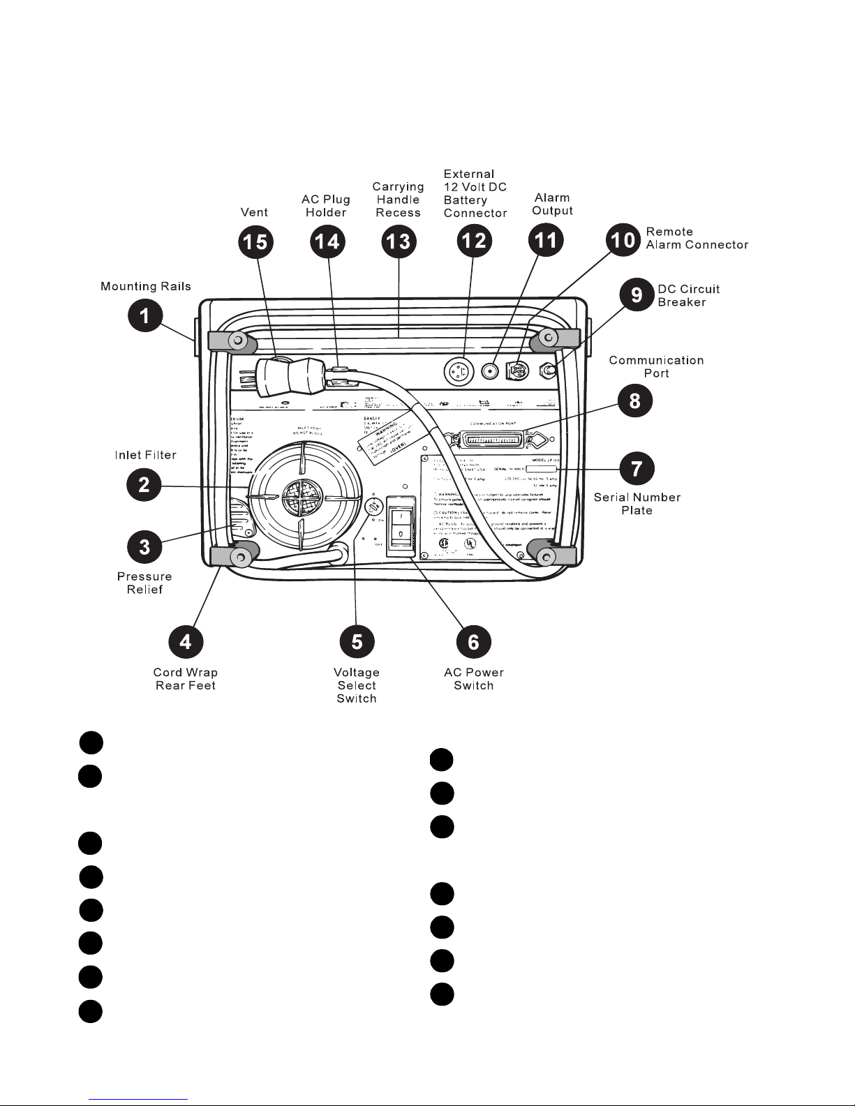
Back Panel (LP20 shown)
Back Panel (LP20 shown)Back Panel (LP20 shown)
Back Panel (LP20 shown)
Mounting Rails Connection for accessories.
INLET FILTER with Screw Off Cap Patient air
is drawn through this filter. Protects airflow
and allows for easy filter change. Do not block.
Pressure Relief
Cord Wrap and Rear Feet
Voltage Select Switch
AC Power Switch/Circuit Breaker
Serial Number Plate
COMMUNICATIONS PORT Connector for
optional printer.
DC Circuit Breaker
REMOTE ALARM Connection
ALARM OUTPUT (LP20 only) 1/4" phone
jack for connecting the ventilator to a nurse
call station.
EXTERNAL 12VDC BATTERY Connector
Rear Carrying Handle Recess
AC Plug Holder
Vent Do not block.
1
2
3
4
5
6
7
8
9
10
11
12
13
14
15

Operating Controls
Operating ControlsOperating Controls
Operating Controls
LP6 Plus, LP10, and LP20 Technical Manual
November 2000
Page 2-5
Page 2-5Page 2-5
Page 2-5
Operating Controls
Operating ControlsOperating Controls
Operating Controls
War ning
War ningWar ning
War ning Periodically check the control panel to be sure that the
Periodically check the control panel to be sure that thePeriodically check the control panel to be sure that the
Periodically check the control panel to be sure that the
controls are on the prescribed settings. The settings should
controls are on the prescribed settings. The settings shouldcontrols are on the prescribed settings. The settings should
controls are on the prescribed settings. The settings should
not be changed without the order of a physician.
not be changed without the order of a physician.not be changed without the order of a physician.
not be changed without the order of a physician.
MODE Control: Selects modes of operation.
See page 2-6.
VOLUME Control: Sets the breath volume.
Push in, then turn the knob to change the set-
ting. When adjusted, the volume changes in
100 ml steps during each breath until the new
volume is reached.
BREATH RATE Control: Adjusts the number of
breaths per minute.
INSPIRATORY TIME Control: Adjusts delivery
time for the breath.
BREATHING EFFORT Control: Adjusts the
patient effort needed to trigger a machine deliv-
ered breath. Push in, then turn to change the
setting. When a breath is sensed, the BREATH-
ING EFFORT indicator lights.
LOW ALARM: Sets the low pressure limit. The
low pressure alarm sounds if this limit is not
reached for two consecutive breaths.
HIGH ALARM/LIMIT: Sets the high pressure
alarm or high pressure limit. The high pres-
sure alarm sounds when the setting is
exceeded (except in Pressure Limited mode).
The alarm stops when the pressure drops to a
lower level. Inspiration ends when the set point
is reached.

Modes of Operation
Modes of OperationModes of Operation
Modes of Operation
LP6 Plus, LP10, and LP20 Technical Manual
November 2000
Page 2-6
Page 2-6Page 2-6
Page 2-6
Modes of Operation
Modes of OperationModes of Operation
Modes of Operation
Modes are set by a 4-position MODE
switch. The modes are as fol-
lows:
• Standby
• Assist/Control
• SIMV
• Pressure Cycle
Standby
StandbyStandby
Standby In this mode, the ventilator is placed in a Standby mode, while both
the external or internal batteries are being recharged. AC power
must be on. Patient assisted ventilation cannot occur in this mode,
but spontaneous breathing through the machine can occur.
Note Batteries charge equally well in all MODE switch positions.
Assist/Control
Assist/ControlAssist/Control
Assist/Control The ventilator functions as an assistant or controller, depending
upon the patient inspiratory efforts. The Assist mode permits the
patient to receive patient-initiated breaths, delivered when the
patients inspiratory effort creates a negative pressure that equals or
exceeds that set on the BREATHING EFFORT control.
If the patient fails to breathe spontaneously or to achieve the
required negative pressure, the ventilator takes control and delivers
a breath to the patient. The ventilator continues to function as a
controller until the patient resumes spontaneous inspiratory efforts
at an acceptable rate and depth (negative pressure).
If the breathing rate is set at less than 6 BPM and the patient makes
no spontaneous effort, the apnea alarm sounds within 10 seconds;
the ventilator then delivers 10 BPM at the preset volume.
SIMV
SIMVSIMV
SIMV The SIMV (Synchronized Intermittent Mandatory Ventilation) mode
permits patients to breathe spontaneously between mandatory
machine-delivered breaths. This mode is frequently used where
sleep apnea may occur, to assist patients with advanced COPD, or
to wean patients from mechanical ventilation.
Under normal SIMV operation, the ventilator delivers mandatory
breaths at a rate set on the BREATH RATE control. The ventilator moni-
tors the patients spontaneous breathing and synchronizes these
mandatory breaths to improve patient comfort.

Modes of Operation
Modes of OperationModes of Operation
Modes of Operation
LP6 Plus, LP10, and LP20 Technical Manual
November 2000
Page 2-7
Page 2-7Page 2-7
Page 2-7
If the patients inspiratory efforts stop, the following occurs:
•For preset SIMV rates between 1 and 5 BPM, an apnea alarm
sounds after 20 seconds, and the ventilator delivers 10 BPM at
the set volume.
•At rates of 6 BPM or greater, the ventilator will continue to
deliver mandatory breaths at the set rate and volume; the apnea
alarm will not sound.
Pressure Cycle
Pressure CyclePressure Cycle
Pressure Cycle This mode is similar to the Assist/Control mode with the exception
that the HIGH ALARM/LIMIT (pressure) control determines inspiratory
cutoff. Therefore, if the pressure limit set on the HIGH ALARM/LIMIT con-
trol is reached before the set inspiratory volume is delivered, this
pressure limit terminates inspiration, regardless of volume deliv-
ered, and no alarm sounds. The high pressure limit may be selected
from 15 to 90 cmH2O above atmospheric pressure. If the termina-
tion is ineffective, causing the pressure to exceed the high pressure
limit setting by more than 10 cmH2O, the HIGH PRESSURE light and
audio alarm activate.
If the patient makes no effort to breathe, the ventilator will take con-
trol and deliver air. Exactly how this occurs depends on the BREATH
RATE setting:
With BREATH RATE
set at 1-5 BPM: If the patient does not start a breath
for 10 seconds, an apnea alarm signals the caregiver; the ventilator
delivers 10 breaths per minute at the set volume, or until it reaches
the set pressure limit.
With BREATH RATE set at 6 BPM or greater: The ventilator will continue
to deliver breaths at the set rate. The apnea alarm will not sound
unless the ventilator cannot deliver a breath.

Ventilator Parameters
Ventilator ParametersVentilator Parameters
Ventilator Parameters
LP6 Plus, LP10, and LP20 Technical Manual
November 2000
Page 2-8
Page 2-8Page 2-8
Page 2-8
Ventilator Parameters
Ventilator ParametersVentilator Parameters
Ventilator Parameters
Vo l u m e
Vo l u m eVo l u m e
Vo l u m e The delivered volume, or tidal volume, is set using the front panel
VOLUME control. This push-to-turn control sets piston excursion,
with continuous settings ranging from 100 to 2200 ml.
Breath Rate
Breath RateBreath Rate
Breath Rate Breathing rates (breaths per minute) are adjustable using the BREATH
RATE control. The control permits rates of 1 to 20 BPM (in increments
of 1 BPM), and 22 to 38 BPM (in increments of 2 BPM).
Inspiratory or I-Time
Inspiratory or I-TimeInspiratory or I-Time
Inspiratory or I-Time The INSPIRATORY TIME control adjusts the rate of air flow being delivered
into the patients lungs, thereby varying the amount of time that is
required to deliver the set volume. Inspiratory time settings range
from 0.5 to 1.0 sec. (in increments of 0.1 sec.), and 1.5 to 5.5 sec-
onds (in increments of 0.5 sec.). Expiratory time and the I/E ratio
are determined by the INSPIRATORY TIME and BREATH RATE settings; flow
rate is determined by the VOLUME and INSPIRATORY TIME settings.
Note BREATH RATE and INSPIRATORY TIME settings that would result in
inspiratory time longer than expiratory time will cause a SETTING
ERROR alarm. The ventilator will deliver at the set inspiratory
time at an I/E ratio of 1:1.
Breathing Effort
Breathing EffortBreathing Effort
Breathing Effort The BREATHING EFFORT control allows the operator to set the patient
effort necessary for triggering a machine-delivered breath, or to
reset the apnea alarm (at breathing rates of 1 - 5 BPM). Settings are
continuous from -10 to +10 cmH2O, with zero being atmospheric
pressure. When a sufficient breathing effort is sensed, the green
BREATHING EFFORT indicator lights. Control settings above zero (+) are
used to compensate for Positive End Expiratory Pressure (PEEP).
Warning
WarningWarning
Warning BREATHING EFFORT
settings above zero without the use of PEEP
settings above zero without the use of PEEPsettings above zero without the use of PEEP
settings above zero without the use of PEEP
may cause the ventilator to autocycle (come on and off
may cause the ventilator to autocycle (come on and offmay cause the ventilator to autocycle (come on and off
may cause the ventilator to autocycle (come on and off
repeatedly without patient effort).
repeatedly without patient effort).repeatedly without patient effort).
repeatedly without patient effort).

Ventilator Parameters
Ventilator ParametersVentilator Parameters
Ventilator Parameters
LP6 Plus, LP10, and LP20 Technical Manual
November 2000
Page 2-9
Page 2-9Page 2-9
Page 2-9
Pressure Alarms
Pressure AlarmsPressure Alarms
Pressure Alarms A front panel LOW ALARM control sets the low pressure limit. Available
alarm limits are 2 to 32 cmH2O (increments of 2 cmH2O). The alarm
sounds only after the low pressure setting has not been achieved for
two consecutive breaths.
Note On the LP20, the audible alarm is double-pulsed for Low Pressure
alarm events.
A separate HIGH ALARM/LIMIT control permits the operator to set the
high pressure limit point. In Assist/Control or SIMV ventilation, the
alarm will sound whenever the high alarm setting is exceeded, but
the alarm automatically stops when the pressure drops to a level
below the limit. This control also sets the high pressure limit for
pressure limited ventilation. In this mode, inhalation is terminated
when the high pressure alarm set point is exceeded. The high pres-
sure alarm does not sound in the PRESSURE LIMITED mode unless
the pressure limit is exceeded by 10 cmH2O or more. Available set-
tings are 15 to 90 cmH2O in increments of 5 cmH2O.
Supplemental Oxygen
Supplemental OxygenSupplemental Oxygen
Supplemental Oxygen The ventilator includes provisions for the addition of prescribed sup-
plemental oxygen. The ventilator delivers up to 40% oxygen concen-
tration when the oxygen elbow and fitting is used. Concentrations
up to 100% are attainable when oxygen is delivered through the
inlet filter port (located on the rear panel), using the Oxygen Enrich-
ment Kit. Instructions for delivering supplemental oxygen are
included with these accessories.
PEEP
PEEPPEEP
PEEP PEEP (Positive End Expiratory Pressure) is accomplished with the
ventilator by connecting an accessory valve to the patient circuit.
The ventilator is PEEP-compensated for up to +10 cmH2O. Complete
PEEP instructions are included with these accessories.
Humidification
HumidificationHumidification
Humidification When humidification is prescribed, several humidification devices
are compatible with the ventilator. Under normal extended use, an
active humidifier is often recommended. Nellcor Puritan Bennett can
supply a mounting bracket that is especially designed for the most
popular humidifiers. Connection information is supplied with the
mounting bracket.
A passive, in-line regenerative humidifier such as an artificial nose
is commonly used to conserve humidification during patient trans-
port or wheelchair use. It is intended for short-term use only. The
regenerative humidifier retains portions of the exhaled heat and
humidity, to aid in conditioning subsequent inhalations.

Ventilator Parameters
Ventilator ParametersVentilator Parameters
Ventilator Parameters
LP6 Plus, LP10, and LP20 Technical Manual
November 2000
Page 2-10
Page 2-10Page 2-10
Page 2-10
12-Volt External Battery
12-Volt External Battery12-Volt External Battery
12-Volt External Battery
Capability
CapabilityCapability
Capability
The ventilator can operate from a mobile power source by connect-
ing the ventilator to a 12 V battery and disconnecting the AC power.
A POWER SWITCHOVER alarm signals the change from an AC power
source to an external battery. A deep-cycle battery, 74 amp-hour in
good condition, can operate the ventilator without recharging for
approximately 24 hours. A gel-cell type battery (34 amp-hour) can
operate for approximately 10 hours between recharges. The ventila-
tor is capable of recharging an external battery, but it is less effi-
cient than using a standard battery charger. Approximately three
hours recharge time is required for each hour of use.
Internal Battery
Internal BatteryInternal Battery
Internal Battery The ventilator switches to its internal battery should the AC power
source fail or the unit become disconnected from the power source.
The internal battery also takes over automatically when power from
an external battery becomes inadequate. A POWER SWITCHOVER alarm
signals the change to internal power. The ventilator can operate
from 30 to 60 minutes on the internal battery, depending on the
charge level and on the control settings. Therefore, the internal bat-
tery should be used only for emergency power backup.
The amber INTERNAL BATTERY light flashes continuously, and a single-
tone audio alarm sounds every five minutes when the internal bat-
tery is in use. The ventilator charges the internal battery in three
hours when the ventilator is connected to AC power and the MODE
switch is in any position. A discharged internal battery must be
recharged for at least three hours prior to turning off the ventilator
to prevent shortening internal battery life.
Caution
CautionCaution
Caution An external battery must be recharged immediately after use. A
standard battery charger is strongly recommended.
Caution
CautionCaution
Caution
The internal battery must be recharged for three hours immedi-
ately after use. An external battery cannot recharge the internal
battery.
Warning
WarningWarning
Warning If the patient’s health or safety would be jeopardized by
If the patient’s health or safety would be jeopardized byIf the patient’s health or safety would be jeopardized by
If the patient’s health or safety would be jeopardized by
long-term power failure, a reliable backup power source is
long-term power failure, a reliable backup power source islong-term power failure, a reliable backup power source is
long-term power failure, a reliable backup power source is
mandatory. The caregiver and patient are cautioned not to
mandatory. The caregiver and patient are cautioned not tomandatory. The caregiver and patient are cautioned not to
mandatory. The caregiver and patient are cautioned not to
regard the internal battery as long-term power backup.
regard the internal battery as long-term power backup.regard the internal battery as long-term power backup.
regard the internal battery as long-term power backup.

Accessories
AccessoriesAccessories
Accessories
LP6 Plus, LP10, and LP20 Technical Manual
November 2000
Page 2-11
Page 2-11Page 2-11
Page 2-11
Accessories
AccessoriesAccessories
Accessories
A number of accessories are available for the ventilator, including a
printer. For details, see your Nellcor Puritan Bennett Representative.

Specifications
SpecificationsSpecifications
Specifications
LP6 Plus, LP10, and LP20 Technical Manual
November 2000
Page 2-12
Page 2-12Page 2-12
Page 2-12
Specifications
SpecificationsSpecifications
Specifications
LP6 Plus, LP10, and LP20 Volume Ventilators
LP6 Plus, LP10, and LP20 Volume VentilatorsLP6 Plus, LP10, and LP20 Volume Ventilators
LP6 Plus, LP10, and LP20 Volume Ventilators
Power Line
Power LinePower Line
Power Line 110 VAC range (100-127 VAC) or 220 VAC range (220-240 VAC), 50/
60 Hz, external voltage selector switch.
Power Usage
Power UsagePower Usage
Power Usage
Maximum:
Maximum:Maximum:
Maximum: 630 kW per year
Nominal:
Nominal:Nominal:
Nominal: 315 kW per year
Extension Cord Gauge:
Extension Cord Gauge:Extension Cord Gauge:
Extension Cord Gauge: Use three-conductor cord only; up to 49’, use 18 gauge cord; up to
99’, use 16 gauge cord; up to 200’, use 14 gauge cord
External Battery:
External Battery:External Battery:
External Battery: Approximately 20 hrs operation with 75-80 amp-hour 12 VDC deep-
cycle, gel-cell battery. Approximately 10 hrs operation with 35-40
amp-hour 12 VDC deep-cycle, gel-cell battery
Internal Battery:
Internal Battery:Internal Battery:
Internal Battery: Approximately one hour operation
Type
TypeType
Type Volume ventilator
Motor:
Motor:Motor:
Motor: Brushless induction
Pump:
Pump:Pump:
Pump: Piston, 100-2200 ml tidal volume capability
Front Panel Controls
Front Panel ControlsFront Panel Controls
Front Panel Controls
Alarm Silence/Reset:
Alarm Silence/Reset:Alarm Silence/Reset:
Alarm Silence/Reset: Push-button to pre-silence alarms before events (LP20 only), silence
alarms during events, or reset alarms after events; used with Bat-
tery Test button to read machine operating hours on Patient Pres-
sure meter
Battery Test:
Battery Test:Battery Test:
Battery Test: Push-button to show battery charge level on the lower window of
Patient Pressure meter (unit must be operating on battery)
Mode:
Mode:Mode:
Mode: Rotary switch to set ventilator operating mode: Standby, Assist/
Control, SIMV, or Pressure Cycle
Low Alarm:
Low Alarm:Low Alarm:
Low Alarm: Rotary switch to set limit for Low Pressure alarm: 2-32 cmH2O in
increments of 2 cmH2O
High Alarm/Limit:
High Alarm/Limit:High Alarm/Limit:
High Alarm/Limit: Rotary switch to set limit for High Pressure alarm (Assist/Control,
SIMV modes), or limit for Pressure Cycle mode: 15-90 cmH2O in
increments of 5 cmH2O
Vo l u m e :
Vo l u m e :Vo l u m e :
Vo l u m e : Push-to-turn knob to set volume: continuously adjustable from 100
to 220 ml
Breath Rate:
Breath Rate:Breath Rate:
Breath Rate: Rotary switch to set breathing rate: 1-20 BPM in increments of one
BPM, and 22-38 BPM in increments of two BPM
Inspiratory Time
Inspiratory TimeInspiratory Time
Inspiratory Time Rotary switch to set time for delivery of set volume: 0.5-1.0 sec. in
increments of 0.1 sec.; 1.2 sec.; and 1.5-5.5 sec. in increments of
0.5 sec.
Breathing Effort:
Breathing Effort:Breathing Effort:
Breathing Effort: Push-to-turn knob to set pressure level for detecting breathing
effort: continuously adjustable from -10 to +10 cmH2O
This manual suits for next models
2
Table of contents
Popular Fan manuals by other brands


Vent-Axia
Vent-Axia VA100/SELV Installation and wiring instructions

Newlux
Newlux WindPure Mist W500 Smart manual

Clarke
Clarke air movers Operating and maintenance instructions

Craftmade
Craftmade Champion CHP60 installation guide

Ellington
Ellington E-VER54ABZ5LKRW installation guide

Sunbeam
Sunbeam FA7400 Instruction booklet