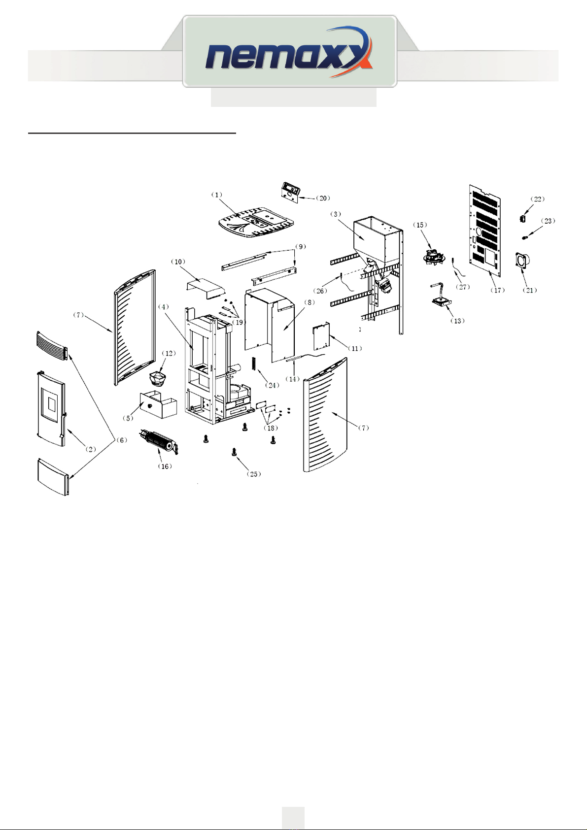
Nemaxx P6 User manual

Version: 9a
13.11.2018
FREESTANDING PELLET STOVE
P6, P9 and P12
ORIGINAL OPERATING INSTRUCTIONS
EN
THIS MANUAL MUST STAY WITH APPLIANCE!
15
0036

2
Version: 9a
13.11.2018
EN
IMPORTANT:
• Please read this entire manual before installation and use of
this pellet fuel burning room heater.
• Failure to follow these instructions could result in property damage,
bodily injury, or even death.
• Save these instructions!
INSTALLER: THIS MANUAL MUST STAY WITH APPLIANCE!
TABLE OF CONTENTS
1. Fuel Requirement ......................................................................................................................... 3
2. Stove Features .............................................................................................................................. 4
3. Method of construction ............................................................................................................... 5
4. Pellet Stove Installation ............................................................................................................... 7
5. Operation .....................................................................................................................................11
6. Cleaning and Maintenance ........................................................................................................ 26
7. Troubleshooting ......................................................................................................................... 32
8. Electronic Plan ........................................................................................................................... 37
Declaration of performance and test report ............................................................................ 39

3
Version: 9a
13.11.2018
EN
1. FUEL REQUIREMENT
Pellets are made from wooden waste, from sawmills and planning workshops, as well as from
residue from forestry operations.
These “starting products” are crushed, dried, and pressed into Pellet “Fuel” without any bonding
agent.
SPECIFICATIONS FOR HIGH QUALITY PELLETS
Caloric Value: 5.3 kWh/kg
Density: 700 kg/m3
Water Content: Max. 8% of the weight
Ash proportion: Max. 1% of the weight Diameter: 5 - 6.5mm
Length: Max. 30mm
Contents: 100% wood untreated and without any bonding agents added
(bark proportion max. 5%)
Packaging: In sacks, made of environmentally neutral or biologically degradable plastic,
or from paper (2-3 layers / similar to cement packaging)
Please ask your pellet stove dealer for tested fuel and a list of monitored fuel
manufacturers.
Using poor quality or prohibited pellet fuel will have a negative eect on the function
of your pellet stove and can also lead to the warranty becoming null and void, as well
as the product liability connected with this.
Observe waste incineration legislation.
Burn only pellets that have been tested.
PELLET STORAGE
In order to guarantee problem free burning of the wooden pellets, it is necessary to store the fuel as
dry as possible and free from impurities.
This appliance is not intended for use by persons (including children) with reduced
physical, sensory or mental capabilities, or lack of experience and knowledge, unless
they have been given supervision or instruction concerning use of the appliance by a
person responsible for their safety:
Children should be supervised to ensure that they do not play with the appliance.

4
Version: 9a
13.11.2018
EN
2. STOVE FEATURES
Pellet stove is advanced designed and has individual fresh air input and venting system.
Negative pressure burning technology causes high eciency and little ash outlet during burning.
It will be shut o automatically by wrong burning or lack of fuel.
Large BTU, quick heating and low fuel cost are its advantages.
1. Main performance
Modell P12 P9 P6
Dimension (WxHxD) MM 543 x 1072
x 593
463 x 971
x 549
463 x 771
x 549
Weight NET/GROSS KG 110 / 130 95 / 110 85 / 100
Air inlet Pipe MM 50 50 50
Air outlet Pipe MM 80 80 80
Heating Performance range KW 3.8-11.5 3-9 3-6
Room heating capacity (m3)
dependent on house insulation
M360-300 60-220 60-120
Consumption for Pellet
(Min-Max)
KG/H 0.6-2.5 0.5-1.75 0.4-1.15
Pellet container capacity KG 28 14 7,5
Automatic Burning Time
(Min-Max.)
H 17-37 10.5-36 13-37
Power supply V / HZ 230 / 50 230 / 50 230 / 50
Average Electrical consumption W/H 80 80 80
Fuse A 333
Eciency % 90% 88% 88%
CO2 content % 9.8% 8% 7.8%
CO emission re. 13% O2 Mg / NM374 84 85
Dust emissions Mg / NM322 18 20
Exhaust air mass ow g/s 7.6 / 4.9 7.1 / 4.3 5.6 / 4.4
Exhaust air temperature OC178 / 92 169 / 112 158 / 113
Chimney draft requirement Pa 12 / 10 12 / 10 12 / 10

5
Version: 9a
13.11.2018
EN
3. STRUCTURE INSTRUCTION
The stove is mainly made up of following items:
1. Top covers
2. Door
3. Pellet Hopper
4. Pellet Chamber
5. Ash Drawer
6. Front Top and bottom cover
7. Side Panels
8. Chamber Insulation cover
9. Shoulder
10. Hot wind driver
11. Motherboard
12. Fire pot
13. Vacuum Switch
14. Igniter
15. Combustion fan
16. Blower
17. Rear Cover
18. Bottom Clear cover
19. Top clear covers
20. Display
21. Exhaust connection
22. Power input socket
(contains the main fuse)
23. Room temperature sensor
24. Handle
25. Stove Feet
26. Safety temperature sensor
27. Exhaust temperature
sensor

6
Version: 9a
13.11.2018
EN
The heater is mainly made up of following items:
1. Combustion burn pot
2. Exhaust fan
3. Room circulation fan and auger motor.
The following is a list of main components and their
functions:
IGNITER
The HEATER comes equipped with an automatic electric
igniter for lighting the fuel when the heater is in lighting
mode only.
The igniter remains energized for the rst eight minutes of
the lighting sequence.
VACCUM SWITCH
The HEATER has a safety vacuum switch located behind
the left door, fastened to the base.
If a low pressure is created in the rebox by a leak,
opening the front door, a blocked ue, or unsealed ash
drawer, the vacuum switch will sense it and cause the
heater to go into a shutdown mode.
AUGER AND AUGER MOTOR
The 2 RPM auger motor turns the auger lifting pellets up the auger tube.
The pellets ed down a tube and into the repot. The auger is controlled by the control board.
OVER TEMPERATURE THERMOSTAT
This safety switch is installed on the bottom of hopper and will shut o the heater if it senses
excessive temperatures (70 degrees).
CONVECTION BLOWER THERMOSTAT
This switch is installed on the vent pipe and turns the convection blower on when the heater is
above 40 degrees.

7
Version: 9a
13.11.2018
EN
4. PELLET STOVE INSTALLATION
All NATIONAL AND LOCAL REGULATIONS AND EUROPEAN STANDARDS SHALL BE
COMPLIED WITH WHEN INSTALLING THE APPLIANCE
Before installing a stove in a room, select the right stove to be able to heat the room.
Please check the STOVES’ Heating area in the Chapter of STOVE FEATURES.
GENERAL INFORMATION
The stove must be connected to a chimney that is approved for solid fuels. The chimney must have a
diameter of at least 80 mm.
The ue system is based on negative pressure in the combustion chamber and a slight overpressure
on the ue gas outlet. It is therefore important that the ue gas connection is tted correctly and is
airtight.
In addition you must ensure that the ue tube does not project into the free cross section of the
chimney.
Only use heat resistant sealing materials, as well as the relevant sealing bands, heat
resistant silicon and mineral wool.
Only authorized technical personnel must carry out assembly work.
NOTE: Please follow the regionally valid building regulations. Contact your master
chimney sweep for information regarding this.
ASSEMBLE THE STOVE BEFORE INSTALLATION

8
Version: 9a
13.11.2018
EN
Ensure that outlet routes to the chimney are not too long.
Avoid too many changes of direction for the ue gas ow to the chimney (e.g. too many corners and
bends).
If you cannot connect directly to the chimney, use a connection piece with cleaning opening if
possible.
For optimum eciency please use the type of connector we recommend.
Horizontal
(This is not recommended,
when the electronic power
is o, the smoke might come
out if the stove is on
Horizontal and up through
the eave.
MAKING THE CHIMNEY CONNECTION

9
Version: 9a
13.11.2018
EN
Method
1. Measure and draw the chimney connection (taking any oor plate thickness into consideration).
2. Chisel out (drill) the hole in the wall
3. Brick in the wall lining
4. Connect stove with the ue tube to the chimney.
FLOOR PROTECTION
For ammable oor surfaces (wood, carpet, etc.) a glass, steel plate or ceramic underlay is required.
ELECTRICAL CONNECTION
The stove is supplied with an approx. 2 m long connecting cable with a plug. The cable must be
connected to a 230 V, 50 Hz electrical supply.
The average electric power consumption is approx. 100 watts during heating.
During the automatic ignition process (duration 10 minutes) approx. 350 watts.
The connection cable must be laid so that any contact with hot or sharp-edged external surfaces on
the stove is avoided.
SAFETY DISTANCES (measured from the outside of the stove)
From non-combustible objects
A > 400 mm, B > 100 mm, C > 100 mm
From combustible objects and to load-bearing walls in reinforced concrete
A > 800 mm, B > 200 mm, C > 200 mm

10
Version: 9a
13.11.2018
EN
COMBUSTION AIR
Each combustion procedure requires oxygen or air. As a rule this combustion air is removed from the
living area for individual stoves. The air taken from the living area must be reintroduced.
In modern houses, very tight tting windows and doors can cause that not enough air ows back.
This situation becomes problematic due to additional ventilation in the house
(e.g. in the kitchen or WC).
The suctioning in of combustion air is performed via the ue gas blower.
The resulting combustion air and suctioning noises are normal operational noises that may occur at
varying volumes depending on the chimney draught, output level or a dirty combustion trough
– NOT A CAUSE FOR COMPLAINT!
Feed of external combustion air
● Steel, HT or exible aluminum pipes must be used.
● Minimum diameter 5 cm/2 inches.
● For longer connection runs the diameter must be increased to approx. 10 cm after approx. 1 m.
● The pipe should not be longer than approx. 4m in total to guarantee adequate air feed and not
have too many bends.
● Should the line lead into the open air, it must end with a vertical 90° downward elbow or with
a wind guard. Should one or more of these conditions NOT be applicable then usually poor
combustion will occur in the stove, as well as air under pressure in the apartment.
We recommend that a ventilating grille be tted in a window near the stove for permanent ventilation.
Further it is possible to extract the combustion air directly from outside or from another room that is
well ventilated (e.g. the cellar).
Please observe:
Your pellet stove works independently of the room air. Negative pressures in the set-up room are not
permissible. Therefore the use of a safety device (e.g. dierential pressure controller) in combination
with room air facilities (e.g. ventilation system, exhaust extraction etc.) is stipulated.

11
Version: 9a
13.11.2018
EN
Put wood pellet fuel into the hopper, connect the power. Then On/O Light is lit (It means that power
is on).
Follow instructions in section “start and operation”
NOTE:
During rst time running, the paint may burn. This may cause unpleasant smell.
Please open the window and door for ventilation.
NOTE:
Before rst usage it is necessary to put a handful of wood pellet to the re pot.
NOTE:
The re pot and underneath the re pot must be clean every time you start the stove!
5. OPERATION
ALL NATIONAL AND LOCAL REGULATIONS AND EUROPEAN STANDARDS SHALL BE
COMPLIED WITH WHEN OPERATING THE APPLIANCE
ATTENTION: When the stove is in operation, please don‘t touch the front. It is extremely hot!

12
Version: 9a
13.11.2018
EN
START AND OPERATION - USERS GUIDE
Please operate the stove as following
(refer to stove structure gure and electrical control gure):
Check the box, pellet grate bar, ash pan then adjust to proper position.
OPERATIONS INSTRUCTIONS – QUICK REFERENCE GUIDE

13
Version: 9a
13.11.2018
EN
ON/OFF
1. Turning the heater on and o is performed with the ON/OFF button .
After switching on, the message, „CLEANING“
will be shown in order to clean the re pot.
2. After rst phase „Cleaning“, the word „Lighting“
will be shown on the display.
During this phase the pellets will be loading in
the burn pot.
This state remains up to when the smokes
temperature doesn’t exceed the planned
threshold.
3. When the Lighting phase is nished, some
minutes will be necessary for the ame
stabilization.
This phase is shown by the word
„STABILIZATION“ which will stay indicated on
the display and will indicate the maintenance
phase of the achieved operational status.
4. For turning o, push .
The display will show:
5. After the temperature in the stove is cold
enough, the word ‚GOODBYE’ is displayed.

Version: 9a
13.11.2018
14
EN
ATTENTION:
During the ame switching o phase and exchanger cooling, you should not switch
the stove on again until the cycle ends;
this state is signalized by the display ‘SWITCHING OFF’
ATTENTION:
If the heater is switched o, the ame will continue burn until the fuel exhaustion in
the melting pot, this will happen in automatically, this can last up to 5-8 minutes.
NOTE:
Before rst usage it is necessary to put a hand of pellets to the re pot.
NOTE:
if the ignition fails, the thermal control will shut o the stove automatically.
Meanwhile, E2 (Error for the ignition failure), will be shown on the display.
If you want to restart it, please check the stove as usually and clean the re pot.
After that, push to clear the word E2.
Follow the above process to ignite and start again.
HOWEVER, it is possible to switch o the heater in every functioning phase.
Turning o the heater is done by pressing the button ON/OFF for two seconds;
make sure the stove is under your supervision, until “Stabilization”.
After you push the button the word „Cooling“ will show on the display.
After the stove’s temperature sinks, the stove will start again, Cleaning-feeding-lighting-stabilization.
How to make the stove skip to the process Stabilization when you think the ame is ok and/or
the stove can work properly?
Push for 3 seconds, and then it will turn directly to Stabilization.
The switching o phase is displayed by the message ‘SWITCHING OFF”.
This will show up to the end of the operation. Whether the heater is switched on or not.
The display will display the hour, the power, and the planned set temperature.

15
Version: 9a
13.11.2018
EN
FLAME POWER VARIATION
Depending on the heating desired, fuel intake quantity can be adjusted from few to many by the fuel
intake button.
For example: Pressing the button the quantity can be changed, the display shows the selected
power.
MINIMUM POWER P4
MEDIUM POWER P2
LOW POWER P3
MAXIMUM POWER P1
ECO STAGE
If the room temperature exceeds the set temperature, the stove is automatically stopped Eco1 or
turns to minimum power in order to save energy Eco2.
If the room temperature drops below the set temperature (3 degrees), it will automatically switch on
again or come back to the previous power level.
How to select these two functions will be shown later.

16
Version: 9a
13.11.2018
EN
SELECTING AUTOMATIC AND MANUAL
Pressing the keys the light shown on this button: will be on or o.
If the light is on, it signals that automatic program is selected. Otherwise it is manual.
DESIRED TEMPERATURE SETTING
Pressing the keys on the display the temperature can be selected.
How to Check the Room temperature, Exhaust (Smoke) Temperature, Safety (Protection)
Temperature which is located under the hopper.
By pressing the button
The number with “R” is the room temperature.
The number with “S” is the temperature of the smoke
The number with “P” is the temperature for the protection.
For example:
It means that the room temperature is 13 degree.

17
Version: 9a
13.11.2018
EN
HOW TO SET DETAILS
SETUP – QUICK REFERENCE GUIDE

18
Version: 9a
13.11.2018
EN
NOTE:
Press and hold the button approx. 2 seconds to enter the setup menu.
Press the button again to exit the setting menu.
Press the button to conrm the settings and move to the next setting point.
This will allow you to navigate through the setup menu.
This procedure applies to all subsequent setting points!
COMBUSTION FAN’S AND BLOWER’S SPEED SETTING
Press and hold the button approx. 2 seconds to enter the setup menu.
The screen will display:
S= SMOKE(EXHUAST FAN) F=FAN(BLOWER)
Press to move from “S 0” TO “F 0”. Press to adjust their speed.
Both of them can be adjusted from 20 to -20. Normally, factory setting is 0. 20 is max. and -20 is min.
Press to save the setting and go to the subsequent setting points P2, P3 and P4.

19
Version: 9a
13.11.2018
EN
After P4, it is P5, this data is related to the exhaust fan’s speed of the “Cleaning” stage.
The adjustable range is also from 20 to -20.
The following is P6; this data is related to the exhaust fan’s speed of the “Feeding”, “Lighting” and
minutes of “Stabilization” stage.
The adjustable range is also from 20 to -20.

20
Version: 9a
13.11.2018
EN
CLOCK SETTING
Begin as described on page 18.
Press until the following message appears:
You can select week or time by keys also using to change the day or time.
To save th e s e t t i n g p r ess and enter the next setting.
CLEANING SETTING
Begin as described on page 18.
Press until the following message appears:
You can adjust the time of cleaning during the operation- “every X mins, last Y” Seconds to cleaning the
burning pot
by the key . For example every 30mins Last 15 seconds:
To save th e s e t t i n g p r ess and enter the next setting.
This manual suits for next models
2
Table of contents
Other Nemaxx Stove manuals