Nemaxx PW18 User manual
KEN002PW18
PELLET STOVE ●PELLETOFEN
POÊLE À GRANULÉS ●STUFA A PELLET
ESTUFA DE PELLETS
Nemaxx PW18
EN INSTRUCTION MANUAL page 2 - 41
DE GEBRAUCHSANLEITUNG Seite 42 - 81
FR MANUEL D'UTILISATION page 82 - 121

Version: 2.0
KEN002PW18 25.11.2019
[ EN ● 2]
TABLE OF CONTENTS
Introduction.......................................................................................................................................................... 3
1. WARNINGS. .......................................................................................................................................................... 4
1.1. Safety instructions ................................................................................................................................................. 4
1.2. Operating instructions ........................................................................................................................................... 5
1.3. Important information for correct disposal of the product with EC Directive 2002/96/EC ..................................... 5
2. Theoretical notions for installation ................................................................................................................... 6
2.1 Pellets ................................................................................................................................................................... 6
2.2 Precautions for installation..................................................................................................................................... 7
2.3. Operating environment ......................................................................................................................................... 7
2.4. Connection to the external air intake .................................................................................................................... 8
2.5. Connection of smoke discharge pipe .................................................................................................................... 9
2.6. Connection to the chimney ................................................................................................................................. 10
2.7. Connectiontoanexternaluewithinsulatedordouble-wallpipe ...................................................................... 10
2.8. Connectiontotheuepipe .................................................................................................................................. 11
2.9. Operatingproblemscausedbydraughtdefectsintheue.................................................................................. 11
2.10. Hydraulic connection ........................................................................................................................................... 12
3. Installation and assembly ................................................................................................................................ 13
3.1. Drawingsandspecications ............................................................................................................................... 13
3.1.1. Dymensions of hydro stove ................................................................................................................................. 13
3.1.2. Technical data sheet ........................................................................................................................................... 14
3.2. Preparation and unpacking ................................................................................................................................. 15
3.3. Hydro connection diagramm ............................................................................................................................... 15
3.3.1. Connections to the system .................................................................................................................................. 16
3.3.2. Filling the water network ..................................................................................................................................... 16
3.3.3. Water characteristics ........................................................................................................................................... 17
3.4. Kit water production ............................................................................................................................................ 17
3.5. Example installation diagrams ............................................................................................................................ 17
3.5.1. Installation diagram for heating system with domestic hot water kit (SUITE/CLUB/MUSA) ................................ 17
3.5.2. Heatinginstallationincombinationwithastoragetank ...................................................................................... 18
3.5.3. Heatinginstallationincombinationwithaboiler .................................................................................................. 19
4. Operation Instructions - Quick reference quide - Safety................................................................................ 20
5. Maintenance and cleaning ............................................................................................................................... 31
5.1. Dailyorweeklycleaningperformedbytheuser ................................................................................................. 31
5.1.1. Before each ignition ............................................................................................................................................ 31
5.1.2. Check every 2/3 days ......................................................................................................................................... 32
5.1.3. Cleaning the glass .............................................................................................................................................. 32
5.1.4. Cleaningthestainlesssteelandsatin-nishsurfaces ......................................................................................... 32
5.1.5. Cleaning of painted parts .................................................................................................................................... 32
5.2. Cleaningtobeperformedbyspecializedtechnician........................................................................................... 32
5.2.1. Cleaning the heat exchanger and the pipe unit ................................................................................................... 32
5.2.2. Shutting the stove dovn (end of season) ............................................................................................................ 33
5.3. Check of internal components ............................................................................................................................ 34
6. Problems / Causes / Solutions ........................................................................................................................ 35
7. Electrical diagrams ........................................................................................................................................... 37
Declaration of performance and test report ................................................................................................... 39
The full text of the Declaration of Conformity can be found here: https://efulllment-online.com/downloads/
Version: 2.0
KEN002PW18 25.11.2019
[ EN ● 3]
IMPORTANT:
●Please read this entire manual before installation and use of this pellet fuel burning room heater.
●Failure to follow these instructions could result in property damage, bodily injury, or even death.
●Save these instructions!
INSTALLER: THIS MANUAL MUST STAY WITH APPLIANCE!
INTRODUCTION
Dear Customer,
Inordertoobtaintheoptimumperformanceofthestoveandtoenjoythewarmthandsenseofwellnessbeing
thatthewarmthoftheamecanspreadinyourhome,werecommendthatyoureadthismanualcarefully
beforemakingtherststart-upofthestove.
Congratulationsagain,foryourchoice,pleasenotethatthepelletstoveMUSTNOTbeusedbychildren,which
shouldalwaysbekeptatasafedistance!
Revisionstothepublication
Inordertoimprovetheproduct,toupdatethispublicationthemanufacturerreservestherighttomakechanges
without notice.
Consultation
●Take care of this manual and keep it in a place of easy and quick access
● Ifthismanualshouldbelostordestroyed,orifstillinpoorcondition,askforacopyfromyourdealer
● Akeytopicorthatrequiresspecialattentionishighlightenedina"boldtext".
Symbols on this manual
WARNING
Thiswarningsymbolindicatesthatyoureadandunderstandthemessagethatisreportedasthe
non-observanceofwhatiswritten,couldcauseseriousdamagetothestoveandputatriskthesafetyof
the user.
INFORMATION
Thissymbolisintendedtoemphasizetheimportantinformationfortheproperfunctioningofthestove.A
failure to comply with the requirements affect the use and operation of the stove will prove unsatisfying.
SEQUENCE OF OPERATIONS
Indicatesasequenceofbuttonstopresstoaccessthemenuormakeadjustments.
INSTRUCTION MANUAL
Indicates you should read this manual or instructions.

Version: 2.0
KEN002PW18 25.11.2019
[ EN ● 4]
1. WARNINGS
1.1 SAFETY INSTRUCTIONS
● Installation,electricalconnection,checkthattheinstallationandmaintenanceareperformedonlybyquali-
edandauthorizedpersonal.
●Install the heater according to the regulations of the place, region or state.
● Thisapplianceisnotintendedtobeusedbypeople(includingchildren)withreducedphysical,sensory,
mental, or with limited experience and knowledge, unless they are trained to use the device or supervised
bythepersonwhoisfullyresponsibleforhissecurity.
●For the correct use of the stove and electronic equipment connected to it and to prevent accidents it is
importanttofollowandobserveallindicationsandinformationandinstructionsreportedinthismanual.
● Theuse,regulationandsettingsmustbecarriedoutbyanadult.Errorsorbadsettingscancausehazar-
dous conditions and / or erratic operation.
● Beforestartinganyoperation,theuseroranyonewhoisabouttooperateonthestovemusthavereadand
correctlyandcompletelyunderstoodtheentirecontentsofthisinstructionbooklet.
● Thestovemustbeintendedsolelyforthepurposeforwhichitisintended.Anyotheruseisconsideredim-
properandthereforedangerousunderthefullresponsibilityofthosewhomakeimproperuse,andtherefore
void with immediate effect a guarantee thereof.
●Do not use the stove as a ladder or support structure.
●Do not put towels on the stove to dry.
● Anyclothesorsimilarmustbekeptataspecicdistancefromtheheater,duetopossiblerehazard.
● AnyliabilityformisuseoftheproductissolelyresponsibleanddesignraisesGracefromallcivilandcrimi-
nalresponsibility;
● Anytypeofunauthorizedtamperingorsubstitutionofnon-originalpartsofthestovecanbedangerousto
the operator safety and lifts manufacturer from all civil and criminal.
● Mostofthesurfacesareveryhot(door,doorhandle,frontdoorglass,uepipes,etc..).Itistherefore
necessary to avoid contact with these parts without adequate protective clothing or special thermal protec-
tion, such as gloves and thermal protection systems devices such as "cold hands", not supplied with this
ovenandcompleteresponsibilityanddiscretionoftheenduser.
● Explaincarefullythedangertotheelderly,disabledandparticularlychildren,keepingthemawayfromthe
stove during operation.
● Itis'forbidden'tooperatethestovewiththedooropenorwithbrokenglass.
● Donottouchthestovewithwethands,beinganelectricalappliance.Alwaysremovethepowercordbefore
opening.
●Before performing any cleaning or maintenance work make sure, in advance, to disconnect the heater from
themainsbyunpluggingthepowercable.
● Incaseofreinthechimney,turnoffthestove,pleasedisconnectfromthenetworkandneveropenthe
door. Then call the appropriate authorities.
● Thestovemustbeelectricallyconnectedtoanetworkwithgroundeddischargefacility.
● Thestovemustbeconnectedtoanelectricalnetworkappropriatelysizedtotheelectricpowerofthestove.
● Incorrectinstallationorpoormaintenance(non-conformingtotheinformationinthisbooklet)cancause
damagetopersons,animalsorthings.Inthiscasemanufacturerisrelievedofanycivilorcriminalliability.

Version: 2.0
KEN002PW18 25.11.2019
[ EN ● 5]
1.2 OPERATING INSTRUCTIONS
●Turn off the heater in case of failure or malfunction.
● NEVERmanuallyloadthepelletintotheburner.
● Theaccumulationofunburnedpelletsintheburnerafterrepeated"misre"mustberemovedbefore
proceeding with a new ignition.
●Do not wash the inside of the stove with water.
●Do not wash the stove with water. Water may enter the unit and damage the electrical insulation, causing
electric shock.
● Donotexposeyourbodytohotairforalongtime.Donotoverheattheroomwhereyouarestayingand
wherethestoveisinstalled.Thiscandamagethephysicalconditionandcausehealthproblems.
● Donotexposetodirecttheowofhotairplantsoranimals.Itcouldhaveharmfuleffectsonplantsor
animals.
● DonotuseotherfuelotherthanDINPLUSCertied-ÖNORMwoodpellets.
● Installthestoveinasuitablelocationwhichhasavailableallnecessaryfacilitiesrequiredsuchasrepre-
ventionfacilitiesandallnecessaryutilitiesareavailablesuchas-butnotlimited-powersupplies(airand
electric) and exhaust fume, in conformity with the provisions in force.
● Thestorageofthestoveandtheceramiccoatingmustbestoredinadryandhumidityfreepremises.
● Itisrecommendedtoplacethestovedirectlyontheoor,andwhereasthisoorismadeofammable
materials, in this case it is required to isolate properly.
● Neverturnonanyheaterwithammablematerialsintheeventoffailureoftheignitionsystem.
INFORMATION
● Incaseofanyproblems,getintouchwithyourdealer,oraqualiedauthorisedengineer,andifarepairis
necessary, insist on the use of original spare parts.
● Useonlythefuelrecommendedbymanufacturer(forItalypelletswithadiameterof6mmandforother
European countries with a diameter of 6-8 mm) and provided only with an automatic supply system.
● Periodicallycheckandcleanthesmokeoutletducts(connectiontotheuepipe).
● Accumulatedunburntpelletsintheburnerafterrepeatedfailedignitionsmustberemovedbefore
1.3 IMPORTANT INFORMATION FOR CORRECT DISPOSAL OF THE PRODUCT IN ACCORDANCE WITH
EC DIRECTIVE 2002/96/EC
Attheendofitsworkinglife,theproductmustnotbedisposedofasurbanwaste.
Itmustbetakentoaspeciallocalauthoritydifferentiatedwastecollectioncenterortoadealerprovidingthis
service.
Disposingofaapplianceseparatelyavoidspossiblenegativeconsequencesfortheenvironmentandhealth
derivingfrominappropriatedisposalandenablestheconstituentmaterialstoberecoveredtoobtainsignicant
savings in energy and resources.
As a reminder of the need to dispose of appliances separately, the product is marked with a crossed-out
wheeleddustbin.
Version: 2.0
KEN002PW18 25.11.2019
[ EN ● 6]
2. THEORETICAL NOTIONS FOR THE INSTALLATION
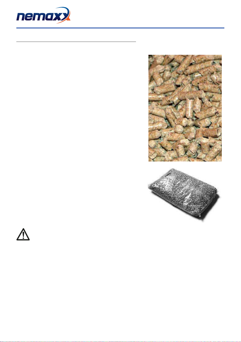
2.1 PELLETS
Thepelletisobtainedbyprocessingthesawdustproduced
duringworkingwoodandtimber(driedwoodandpaintfree).The
compactnessofthematerialisguaranteedbytheligninwhichis
contained in the wood itself and allows the production of pellets
withouttheuseofgluesorbinders.
The market offers different types of pellets with characteristics
thatvarybasedonmixturesofwoodused.Thediametervaries
between6and8mm,withastandardlengthbetween5and30
mm. The pellets of good quality has a density ranging from 600
to more than 750 kg/m3with a water content that is maintained
between5%and8%ofitsweight.
Inadditiontobeinganenvironmentallyfriendlyfuel,asyoupush
thelimitsofwoodresiduesresultinginacleaner-burningthan
that produced with fossil fuels, the pellets also have technical
advantages.Whileagoodwoodhasacaloricvalueof4.4kW/kg
(15%RH,after18monthsofseasoning),thepelletis4.9kW/kg.
Toensuregoodcombustion,andnopowerproblems,itisimpera-
tive that the pellets are stored in a dry place, protected from dirt,
and the thermo stove is placed in a place where the conditions
arethesame,nottogeneratethesametypeofproblemsonthe
power pellets in the tank. The pellet is usually supplied in 15 kg
bags,sostorageisveryhandy.
Agoodqualitypelletensuresgoodcombustionloweringharmful
emissions into the atmosphere.
If the fuel is poor, the more often cleaning inside the grate and the combustion cham-
ber will be required.
ThemaincerticationsofqualityforpelletsintheEuropeanmarketareDINplusandÖNormM7135;these
ensure respect of:
● Caloricpower:4.9kW/kg
● Watercontent:max10%ofweight
● Percentageofashes:max0,5%ofweight
●Diameter: 5 - 6 mm
●Length: max 30 mm
● Contents:100%untreatedwood,withnoaddedbondingsubstances(barkpercentage5%max)
● Packaging:insacksmadefromecologicallycompatibleorbiologicallydecomposingmaterial

Version: 2.0
KEN002PW18 25.11.2019
[ EN ● 7]
Nemaxxstronglyrecommendsusingcertiedfuelinitsstoves(DINpluseÖNormM7135).
Theuseoffuelofinferiorqualityornotconformingtothespecicationgivenabovecompro-
mises the running of your stove and can therefore lead to the termination of the guarantee
andofthemanufacturer'sresponsibilityfortheproduct.
Nemaxx pellet stoves run exclusively on pellets with a diameter of 6 mm (only for Italy) and 6-8 mm
(European countries) with lengths that go from 5 mm to 30 mm.
2.2 PRECAUTIONS FOR INSTALLATION
IMPORTANT!
Installationandassemblyofthestovemustbecarriedoutbyqualiedpersonnel.
Thestovemustbeinstalledinasuitablepositiontoallowthenormaloperationsofopeningandordinary
maintenance.
Thesitemustbe:
● capableofprovidingtheenvironmentalconditionsforoperation
● equippedwithpowersupply230V50Hz
● capableoftakinganadequatesystemforsmokedischarge
●provided with external ventilation
●provided with an earth connection complying with IEC standards
Thestovemustbeconnectedtoauepipeoraninternalorexternalverticalductconformingtocurrentstan-
dardsUNI7129-71319615.Thestovemustbepositionedinsuchawaythattheelectricalplugisaccessible.
The stove must be connected to a ue pipe or a vertical duct which can discharge the fumes at the hig-
hest point of the building. The fumes are however derived from the combustion of wood products and
if they come into contact with or close to walls, they can make dirty marks. Also take care because the
fumes are very hot but almost invisible, and can cause burns on contact. The holes for the passage of
the smoke pipe and for the intake of air from outside should be made before positioning the stove unit.
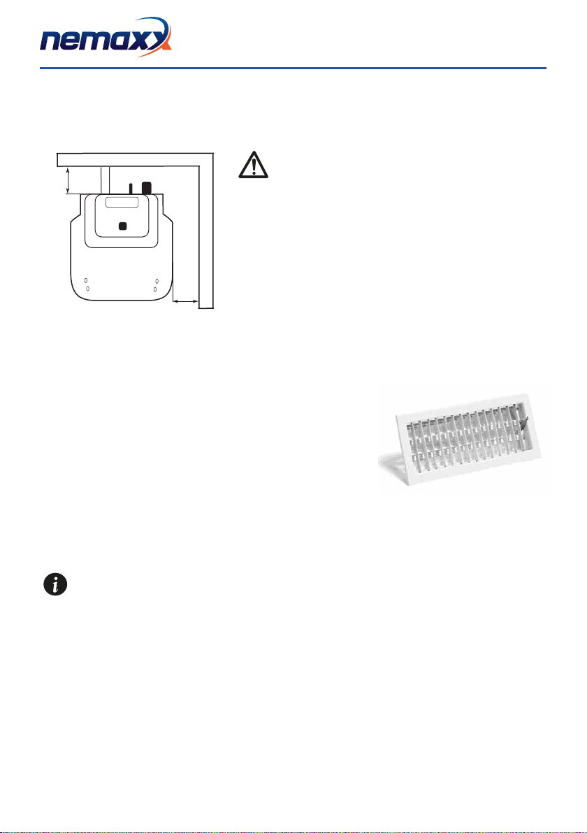
2.3 OPERATING ENVIRONMENT
IMPORTANT!
Forproperoperation,andauniformdistributionoftemperature,
thestoveshouldbeplacedinalocationwithanairowthat
guaranteestheairneededforcombustionofthepellets(should
beavailableapproximately40m3/h) according to the installation
and the second regulations in the country.
Thevolumeoftheenvironmentmustnotbelessthan30m3.
The air must enter through permanent openings on the walls
(near the stove) with a minimum of 100 square centimeters.
Theseopeningsmustbemadesothattheycannotbeobstructed
inanyway,andallowproperairow.Aircanalsobetakento
ventilateroomsadjacentprovidedtheyareequippedwithairhose
andarenotusedasabedroomandbathroom,orwherethereis
100 cm2
20 cm
Version: 2.0
KEN002PW18 25.11.2019
[ EN ● 8]
norehazardsuchas:garages,sheds,storageofcombustiblematerials,etc.,strictlycomplyingwiththe
requirementsundercurrentrules.Itisabsolutelyprohibitedtoinstallationthestoveinbedrooms,bathrooms,
andwhereitisalreadyinstalledanotherdheatingdevicewithoutadequateairow(replace,stove,etc.).
Itisexpresslyprohibitedtheplacementofthestovein
environmentswithexplosiveatmospheres.Theoorof
theroomwherethestovewillbeinstalledmustbesized
appropriately to support the weight of the stove itself (which
shouldbeconsideredinadditiontotheweightofthemachine
saidthesameloadmustbeaddedamaximumof60kgforthe
pellets, and 80 kg for water). When installing, keep a minimum
distancefromobstaclesandnotammable(B)of20cmtherear
to, lateral (LR) of 20 cm and anterior (C) of 80 cm. In the presence
ofobjectsbelievedtobeparticularlysensitivesuchasfurniture,
curtains, sofas, carpets, etc., greatly increase the distance of the
stovefromthem.Inthepresenceofwoodenooroor-prepare
the plan and in accordance with rules in force in the country, on
reprevention.
A
B
2.4 CONNECTION TO THE EXTERNAL AIR INTAKE
It is essential that the room where the stove is installed, the stove can
availofanairowinsufcientquantityasitisrequiredbytheregular
combustionequipmentandventilation.Thiscanbedonebymeansof
permanentopeningsonthewallsthatgivetheroomtobeventilatedto
the outside, ventilation ducts or through individual or collective. Within
this scope, the outer wall near the stove must have an opening minimum
100 cm2,protectedbyagridinsideandoutside.
The air intake must also:
●becommunicatingdirectlywiththeinstallationenvironment
●beprotectedbyagrate,wiremeshorothersuitableprotection,provideditdoesnotreducetheminimumsection.
●positioninasuitablemannerastopreventitfrombeingobstructedinanyway
It is prohibited to connect the air directly to the stove (communicating directly from the out-
side), to avoid compromising thermodynamic performance, however it is required that the
conditions still guarantee about 50 m3/h of air replacement, as provided in the current UNI
10683.

Version: 2.0
KEN002PW18 25.11.2019
[ EN ● 9]
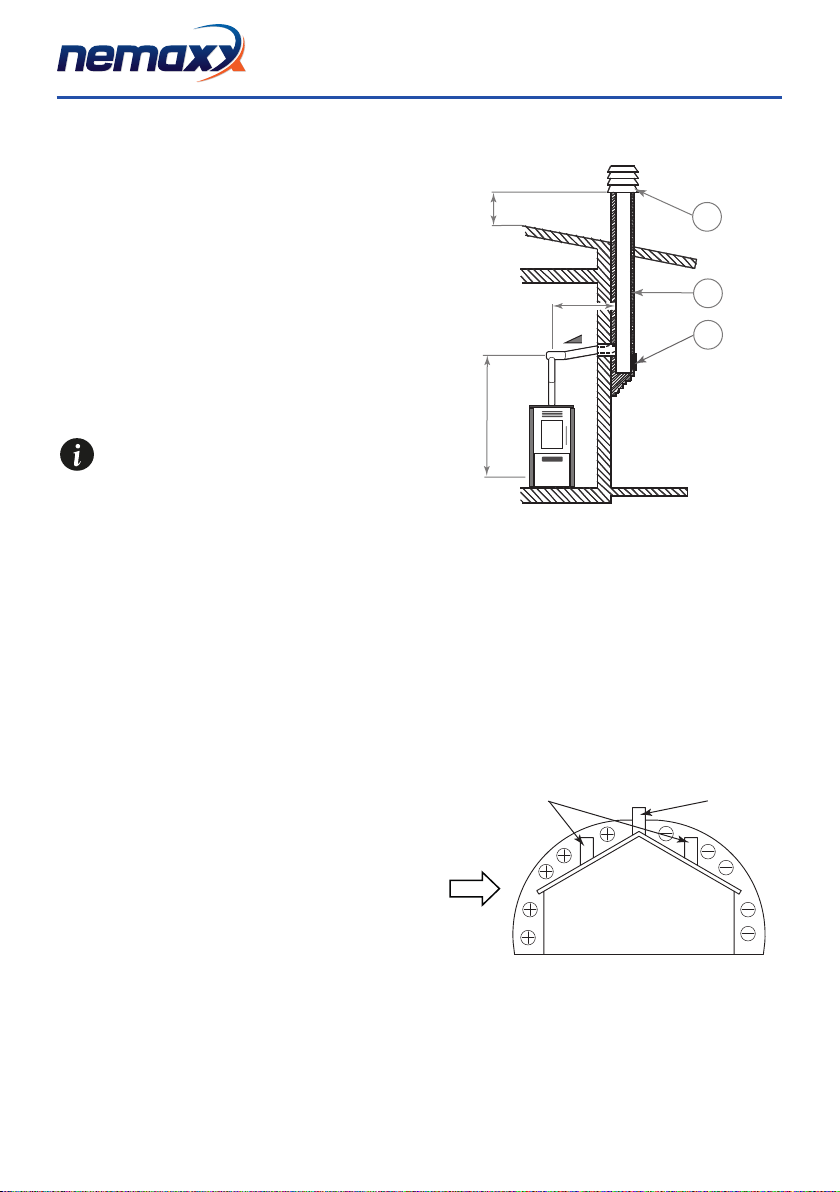
2.5 CONNECTION OF SMOKE DISCHARGE PIPE
Whenmakingtheholefortheuepipeitmustbetaken
intoaccountthepossiblepresenceofinammable
materials. If the hole has to go through a wood wall or
otherthermolabilematerial,theinstallerMUSTusethe
Industrial insulated pipe (with min thermal conductivity
of 0.07 W/m°K). The same applies if the stove pipe
mustgoverticalorhorizontalsectionsremainnear
(min.20cm)toaheat-labilewall.
Thecombustionchamberworksindepression,sothe
exhaustductfortheexhaustfumeswillbelinkedto
depressionwheneffectivechimneyasprescribed.
It should always use pipes and ttings with
appropriate seals to ensure airtightness in
order to avoid possible harmful CO fumes
into the environment.
All sections of the exhaust duct must be
inspectable and removable to allow for
periodic cleaning of the interior, which is necessary
for the proper functioning of the system (T-piece
with inspection). Position the stove strict accordan-
ce with all regulatory requirements and attention to
highlighted date
All changes direction 90 degrees of the ue gas channel must be prepared if possible, with the appro-
priate ttings to "T" with inspection. It is absolutely forbidden to use a net at the end of the hose as it
can cause serious problems for the proper and safe operation of the stove.
In connection do not use the chimney sections of pipe horizontally, but always the same place at an
angle of 5° minimum to rise, possibly avoiding the use of a 90-degree (you can use up to 3) and use
preferably 45° curves. It is recommended to not use a total length of the pipe diameter 80 mm, greater
than 6 m in total.
IMPORTANT!
2 - 3 m max
3-5%
H > 4 m
H > 1,5 m
example of pellet stove installation

Version: 2.0
KEN002PW18 25.11.2019
[ EN ● 10 ]
2.6 CONNECTION TO THE CHIMNEY
The chimney must have inside dimensions of no more
than cm. 20X20 or 20 cm diameter. In the case of
larger or poor condition of the chimney (ie: cracks, poor
insulation, etc.) it is recommended to insert stainless
steeltubeinthechimneyofaofsuitablediameterfor
its entire length, to the very top. Check with suitable
instruments that there is a minimum draft. Gua-
ranteed 15 Pa. Atthebottomofachimneyinspection
forperiodicinspectionandcleaning,whichmustbe
done annually. You must ensure that a chimney top is
installed according to regulations for wind force.
This type of connection must guarantee of 15
Pa, allows the correct discharge of smoke with
a natural draft even if there is no electricity.
1. Windproof cowl
2. Flue pipe
3. Inspection
The external pipe must have minimum internal
dimensions of cm. 10X10 or 10 cm diameter. cm,
and maximum. 20X20 or 20 cm diameter. Check with
appropriate tools that there is a draw of 10 Pa. It must
useonly,andonlypipesinsulated(doublewall)within
thesmoothstainlesssteel(stainlesssteelexibletubes
arenotallowed)xedtothewall,toprevent,and/or
minimizecondensationproblems.Atthebottomof
the outer vertical duct an inspection tap for periodic
inspectionsandcleaningtobedoneannually.Youmust
ensure that the chimney is installed according to wind
force.
This type of connection, even in case of mo-
mentary power failure, ensuring the evacuation
of the fumes.
1. Windproof cowl
2. Flue pipe
3. Inspection
2.7 CONNECTION TO AN EXTERNAL FLUE PIPE WITH ISOLATED OR DOUBLE WALL
1
2
3
0,5 m
1
2
3
0,5 m
Version: 2.0
KEN002PW18 25.11.2019
[ EN ● 11 ]
Theconnectionbetweenstoveandchimneyoruefor
theproperoperationmustnotbelessthan5%slope
inthehorizontalsectionswhosetotallengthshould
notexceed1.5meters.andtheverticalbya"T"to
another(changingdirection)mustnotbelessthan1.5
meters.Checkwithsuitableinstrumentsthatthereisa
minimumdraft.of10Pa.Atthebottomofthechimney
inspected for periodic inspections and cleaning, which
mustbeconducted annually.
You must ensure that a chimney is installed according
to wind force.
This type of connection, even in case of mo-
mentary power failure, ensuring the evacuation
of the fumes.
1. Windproof cowl
2. Flue pipe
3. Inspection
2.8 CONNECTION TO THE FLUE PIPE
3
2
1
0,5 m
3 - 5 %
2 - 3 m max
H > 1,5 m
2.9 OPERATING PROBLEMS CAUSED BY DRAUGHT DEFECTS IN THE FLUE
Of all the meteorological and geographical factors that
affecttheoperationofaue(rain,fog,snow,altitude
abovesealevel,periodofinsulation,exposuretothe
cardinal points, etc.) the wind is certainly the most de-
cisive.Infact,besidesthethermaldepressioncaused
bythedifferenceintemperaturebetweentheinside
and the outside the chimney, there is another type of
depression (or overpressure): the dynamic pressure
inducedbythewind.Anascendingwindalwayshas
the effect of increasing depression and then the draft.
Ahorizontalwindincreasesdepressionforproperins-
tallation of the chimney. A descending wind always has
the effect of relieving depression, sometimes inverting
it. In addition to the direction and force of the wind, the
positionoftheueandthechimneyfromtheroofofthe
house and the surrounding landscape is important.
+= HIGH PRESSURE ZONE
-= LOW PRESSURE ZONE
A= LESS FAVOURABLE POSITION
B= MOST FAVOURABLE POSITION
AB
WIND

Version: 2.0
KEN002PW18 25.11.2019
[ EN ● 12 ]
Thewindaffectstheoperationofthereplacealsoindi-
rectlybycreatingzonesoverpressureanddepression
aswellastheoutsidebutinsidethehome.Inareas
directly exposed to the wind (2) can create an internal
overpressure which can promote the draft of stoves and
replaces,butmaybecounteredbyexternaloverpres-
sure if the chimney is placed on the side exposed to the
wind (1). In contrast, in areas opposite to the direction
of the wind (3) can create a dynamic depression that
comes into competition with the natural thermal depres-
siondevelopedbythereplace,butcanbecompensa-
ted(sometimes)byplacingtheexhaustductfromthe
side opposite to the direction of the wind (4)
1
23
4
1-2 = ZONE IN OVER PRESSURE
3-4 = ZONE IN DEPRESSION
WIND
The operation of the pellet stove is noticeably sensitive to the conformation and position of the ue
which is adopted. Hazardous conditions can only be overcome by suitable setting-up of the stove
carried out by qualied personnel.
IMPORTANT!
The connection of the stove to the hydraulic system must be made ONLY by qualied personnel and
can perform the installation in "ART" and in compliance with all statutory and regulatory provisions
in force and not in the country of installation. If the installation of the stove requires interaction with
another existing facility complete with another heater (gas boiler, gas boiler, oil boiler, etc...), is recom-
mended for more qualied personnel who can then be challenged to answer the Full compliance of the
system, per the applicable law, and issuing the certicate. Nemaxx disclaims any liability for damage
to persons or property or in the event of failure or improper operation, if not complied with the above
warnings, and issued the necessary certicates of compliance enforcement work in an appropriate
manner. It is absolutely necessary that the network is designed properly sized to dispose of all the heat
ux produced by the stove to avoid raising the temperature inside the boiler.
IMPORTANT!
2.10 HYDRAULIC CONNECTION
Version: 2.0
KEN002PW18 25.11.2019
[ EN ● 13 ]
3. INSTALLATION AND ASSEMBLY
3.1 DRAWINGS AND SPECIFICATIONS
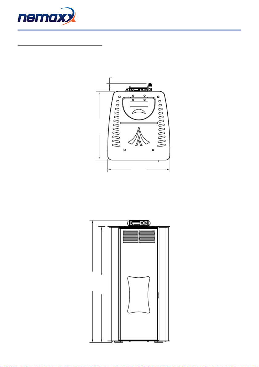
3.1.1 Dimensions of hydro stove
69 mm
546,0 mm
603,0 mm
1074,0 mm
1017,5 mm

Version: 2.0
KEN002PW18 25.11.2019
[ EN ● 14 ]
3.1.2 Technical data sheet
Model Nemaxx PW18
Ratingvoltageandfrequenzy V/HZ 230V/50Hz
Maximum water pressure Bar 1.5
Electronic consumption MAX W / H 380
COemissionat13%oxygen(mg/m3) Max mg / m3185
COemission3%oxygen(mg/m3) Min mg / m3250.1
EfciencyMax % 93.9
EfciencyMin % 92.4
Heat area m3280
Rating power Max / Min kW 18 / 10
Rating power (water) Max / Min kW 12.5 / 6.1
Thermal power to the environment Max / Min kW 4 / 3.9
Ø pellet mm 6
Length of pellet mm 30
Hopper capacity kg 40
AutomaticburningtimeMax/Min H 18 / 11
Weight kg 150
Size(WxHxD) mm 545x1017x682
Ø Air outlet pipe mm 80
Temperature of the smoke output Max / Min °C 89.5 - 80
Flue draught pressure Pa 0.1 - 15
Product data sheet in accordance to regulation EU 2015/1186 Annex IV ProduktdatenblattgemäßVerordnungEU2015/1186AnhangIV
Name or trademark supplier Nemaxx
Model Nemaxx PW18
Energyefciencyclass A+
Direct heat output in kW 5.4
Indirect heat output in kW 16
EEIEnergyEfciencyIndex 123
Usefulenergyefciencyatnominalheatoutputin% 90,8
Usefulenergyefciencyatminimumheadoutputin% 93,3
Specialprecautionsforassembly,installationor
maintenance of the room heater
●Before commissioning, please read and strictly follow the operating instructions
● Thereprotectionandsafetydistancestocombustiblebuildingmaterialsmust
becomplied!
● Thecombustionchambermustalwaysbeabletosupplysufcientcombustion
air.Airsuckingsystemscaninterferewiththecombustionairsupply!
● Heaterswithwatertechnology/boilerstovesmayonlybeputintooperationif
allsafetyequipmentisreadyforoperationandfunctional!
●Use only permited fuels
● Theproductmaynotbechanged
● Theproductmustbecleanedregulary
● Allinstructionsandrulesinthemanualinstructionsmustbeobserved.
AllthedatashavebeenmeasuredusingapprovedpelletsincompliancewithENISO17225-2.
Comply with the warnings and instructions concerning installation and routine maintenance provides in this manual

Version: 2.0
KEN002PW18 25.11.2019
[ EN ● 15 ]
3.2 PREPARATION AND UNPACKING
Openthebox,unloadthestovefromtheplatformwithextremecaution,andplacethedesiredlocation,making
sure that it complies with the requirements.
Thebody,orblockshouldalwaysbehandledexclusivelybytruckinanuprightposition.Youshouldpay
particularattentiontothedooranditsglasstobeshieldedfromshocksthatmightcompromisetheirintegrity.
However,thehandlingoftheproductsmustbedonewithextremecaution.Unpackthestovenearthearea
whereitwillbeinstalled.
The materials that make up the package are neither toxic nor harmful, thus do not require special disposal pro-
cesses. So, the storage, disposal or recycling is eventually complete recovery from the end user in accordance
withapplicablelaws.
Donotstorethereplaceandcoveringswithouttheirpackaging.
Positionthestove,inthecorrectpositionthatrespectsfaithfullyaspreviouslydescribedabove,andproceed
with the connection to the chimney.
Ifyouconnectyourstovetoadischargepipethatrunsthroughthebackwall(totakeinthechimney)pay
extreme caution not to force the entrance in any way.
Iftheueofthestoveisforcedorimproperlyusedtoliftorplacedintoposition,itwillcompromisebeyond
repair,theoperation,andmanufacturerisnotconsideredinanywayresponsibleforsuchamaladroitand/or
neglect in the work, so in these conditions any Recovery operations are excluded from warranty.
3.3. HYDRAULIC CONNECTION DIAGRAM
A1 = Heating water delivery 3/4" M
A2 = Heating water return 3/4" M
C=Safevalve3bar-1/2"F
Ø 50 Ø 80
102
191
89 546 262 197 175
430
331 331
A
B
C

Version: 2.0
KEN002PW18 25.11.2019
[ EN ● 16 ]
3.3.1 CONNECT TO THE SYSTEM
Carry out the connections to the connections illustrated in the diagram corresponding to the previous page
takingcaretoavoidtensioninthepipeandundersizingofthepipes.
IT IS NECESSARY TO PROVIDE THE PROPER CLEANING THE WHOLE SYSTEM BEFORE YOU
CONNECT THE STOVE TO ELIMINATE WASTE AND DEPOSITS
IMPORTANT!
C
D
A
B
A = TAP
B = DOMESTIC SYSTEM
C = PRESSURE DISCHARGE
D = FLEXIBLE PIPES
Always install the heater upstream of the valve gate valve to isolate the same water system or move it move
it if necessary, to perform routine maintenance and / or extraordinary. Connect the heater hoses for not using
theover-constrainthestovetoallowtheplantandthelightshifts.Thepressurereliefvalve(C)mustalwaysbe
connectedtoadrainhose.Thepipemustbesuitabletowithstandthehightemperatureandpressure.
3.3.2 FILLING THE WATER NETWORK
Toloadoftheheater,theheatermustbeequippedwithatap(optional)withanon-returnvalve(D)inorderto
manuallyllthenetwork,youcanusetheloadtapalreadyontheboileronthestove.
Duringthatoperation,theoutletofanyairinthesystemisguaranteedbythepresentautomaticventunderthe
top. To guarantee that the valve discharges air, it is recommended to loosen the grey tap and leave the red tap
locked(refertog.).
Grey plug loosened
- 1 turn
Redplugblocked
Vent valve under the top

Version: 2.0
KEN002PW18 25.11.2019
[ EN ● 17 ]
3.5. EXAMPLE OF INSTALLATION DIAGRAMS
Thediagramsbelowaremerelyindicative.Foraproperconnection,alwaysfollowthenotesoftheplumbingandheatinginstallerwith
proven experience. The hydraulic system must meet the mandatory regulations of the place, region or state. The installation, testing and
certicationofoperationmustbeperformedonlybyauthorizedpersonnel,withtheissueofcerticationthattheworkhasbeencompleted
in a "state of art" performance, attesting the conformity of the work in compliance with laws and regulations. The manufacturer disclaims
anyresponsibilityincaseofnon-compliancetotheabove,especiallyintheabsenceofproofofcerticationworkina"STATEOFART"
execution.
3.5.1 INSTALLATION DIAGRAM FOR HEATING SYSTEM WITH DOMESTIC HOT WATER KIT (SUITE/CLUB/MUSA)
SE Electronic card VD One-way valve
SAutomativ vent TMeasurement of boiler temperature
M Pressure gauge VE Expansion tank 1.5 bar of 6 l.
VS Vent valve 3 bar W3-way motorized valve
VValve SC Plate heat exchanger
P Pump F Flow switch
C Mezhane gas boiler A Pounding absorber
B Boiler RP Pressure reduction valve
BA Storage boiler VSC Boiler / system discharge valve
RA Radiators FIT System lter
PR Radiant panels ADD Softener
PS Solar panels
The lling pressure during cold status should be 1 bar.
If during operation the system pressure drops (due to evaporation of the gas dissolved in water) to values less than the
minimumindicatedabove,theUsershall,actingonthevalvefromtheloadbacktotheinitialvalue.
Foroptimaloperationofthestoveinoperation(hot),theboilerpressuremustbe1.5bar.Donotexceed2bar.Attheendof
theoperationalwaysclosethellingtap.
3.3.3 WATER CHARACTERISTICS
Thecharacteristicsofthewaterforllingtheplant,areveryimportanttoavoidthedepositionofmineralsandthecreationof
depositsalongthepipingwithintheboilerandheatexchangers.Therefore,itisadvisedtocheckwithyourplumber/tterthe
following characteristics:
● Hardnessofwatercirculatinginthesystemtoremedyanyproblemsandlimestonedepositsespeciallyinthehotwater
heat exchanger. (> 25° French)
●Installing a water softener (if the water hardness is > 25° French)
● Fillthesystemwithtreatedwater(demineralized)
●Any set of a circuit condensation.
● Installationofhydraulicshockabsorberstoavoidthephenomenonof"waterhammer"alongthettingsandpipes.
For those with very large systems (with large water content) or who require frequent replenishment of the plants in
the plant to install water softeners, especially because the scale signicantly reduce the thermal conductivity!
3.3.4 KIT WATER PRODUCTION
AllthermostovesareequippedwithHANKSkitfortheproductionofhotwatercharacterizedby:
●Plate heat exchanger
●3-way diverter valve, electric motor-driven
●Electrical Flow meter
● Stainlesssteelnnedpipesandttingsforconnecting
●Pressure valve
Thekithasthetaskofheatinghotwaterfromthewaterlineofthehouse.Atatimewhenthereishotwaterdemandbyopeningatap,
theinternalow-metercommandsthedivertervalvetoconveythehotwatercontainedinsidetheboiler,totheplateheatexchanger.
Thehotwatertemperaturewilldependentonthewatertemperatureinsidetheheater,withapproximation,iscalculatedbyremoving
10°-15°Ctothevaluereadonthecontrolpaneloftheheater(boilerwatertemperature).Forproperlifetimeoperationoftheheat
exchangerplates,itisnecessarytoknowthehardnessofyourwatertopreventfouling,andtoblocktheexchange.
Version: 2.0
KEN002PW18 25.11.2019
[ EN ● 18 ]
Conguration: stare/ego/suite/club/musa/ with domestic hot water kit system of system with closed tank only
for heating by means of radiators
SYSTEM DELIVERY
PRESSURE SAFETY DISCHARGE
SE
SYSTEM RETURN
SYSTEM REFILL
SVS P
V
MV
V
T
VE Vsc
RP
RA RA
RARA
AFlt
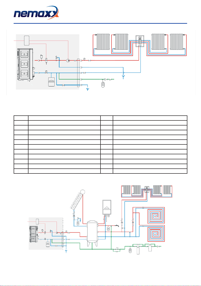
3.5.2 HEATING INSTALLATION IN COMBINATION WITH A STORAGE TANK
SE Electronic card VD One-way valve
SAutomativ vent T Measurement of boiler temperature
M Pressure gauge VE Expansion tank 1.5 bar of 6 l.
VS Vent valve 3 bar W3-way motorized valve
VValve SC Plate heat exchanger
P Pump F Flow switch
C Mezhane gas boiler A Pounding absorber
B Boiler RP Pressure reduction valve
BA Storage boiler VSC Boiler / system discharge valve
RA Radiators FIT System lter
PR Radiant panels ADD Softener
PS Solar panels
Conguration: stare/ego/suite/club/musa/ without domestic hot water kit combined with storage system of system with boiler
and solar panels. System diagram with closed tank for heating with radiators or radiant panels and for the production of
domestic hot water.
PERFORMANCE: HEATING WITH STORAGE SYSTEM PRODUCTION OF DOMESTIC HOT WATER WITH STORAGE SYSTEM
230V 50Hz
230V 50Hz
RA RA
RARA
SYSTEM DELIVERY
PRESSURE SAFETY
DISCHARGE
SYSTEM RETURN
SYSTEM
REFILL
SE
SVS P
T
M
V
VE
Vsc
PS
BA
C
A Add Flt
RP
PR
PR
HOT DOMESTIC
WATER OUTLET
COLD DOMESTIC
WATER INLET

Version: 2.0
KEN002PW18 25.11.2019
[ EN ● 19 ]
3.5.2 HEATING INSTALLATION DIAGRAM IN COMBINATION WITH A BOILER
SE Electronic card VD One-way valve
SAutomativ vent T Measurement of boiler temperature
M Pressure gauge VE Expansion tank 1.5 bar of 6 l.
VS Vent valve 3 bar W3-way motorized valve
VValve SC Plate heat exchanger
P Pump F Flow switch
C Mezhane gas boiler A Pounding absorber
B Boiler RP Pressure reduction valve
BA Storage boiler VSC Boiler / system discharge valve
RA Radiators FIT System lter
PR Radiant panels ADD Softener
PS Solar panels
PERFORMANCE: HEATING WITH STOVE. PRODUCTION OF DOMESTIC HOT WATER WITH BOILER.
Conguration: stare/ego/suite/club/musa/ without domestic hot water kit combined with boiler. Heating with strage production
of domestic hot water with storage system.
COLD DOMESTIC
WATER INLET
HOT DOMESTIC
WATER OUTLET
SYSTEM DELIVERY
SYSTEM RETURN
SYSTEM REFILL
PRESSURE SAFETY DISCHARGE

Version: 2.0
KEN002PW18 25.11.2019
[ EN ● 20 ]
4. OPERATIONS INSTRUCTIONS - QUICK REFERENCE GUIDE
Start / Stop
Auto / Manual
Power Level
Thermostat Temperature
Start
Stop Automatic
Schedule
Power
Level
Skip the process
to stablition
Thermostat
Temperature
Check
Temperature
Press
Start/Stop
Display turns on so you
can change settings with
other buttons
Display turns off after 10
seconds of inactivity
Press &
hold 3
seconds
Start Up Process
commences
Press &
hold 3
seconds
Shutdown Process
commences
Press &
hold 3
seconds
Increase or
decrease the
set point
Press Pellet
Feed Rate
to cycle
through P1,
P2, P3 or P4
Press to
toggle
between
Auto and
Manual
Press to show
current room
temperature
(R)
Press to show
current
Exhaust
temperature
(S)
Press to show
current
Protectiontem-
perature
(P)
Table of contents
Languages:
Other Nemaxx Stove manuals


