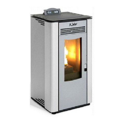
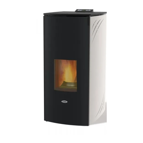
Kalor 24B User manual

USER MANUAL
Ilaria/Nadia 24B/24BDD
Boiler Stoves
Instructions for the correct use and maintenance of
your Kalor wood pellet boiler stove
Distribution and warranty in Ireland by:

A note from the distributor:
Congratulations and thank you for choosing a Kalor wood pellet stove. Kalor is a leading
wood pellet stove brand worldwide, offering leading combustion efficiencies and superior
reliability. You have chosen well!
Kalor stoves are distributed in Ireland by Wood Pellet Stoves.ie, through a network of
Authorised Dealers. We are a company, totally dedicated to wood pellet stoves and our
priorities are quality not just of product but also of installation and maintenance.
We also offer a nationwide network of Authorised Technicians who are specially trained on
Kalor wood pellet stoves. This ensures that your stove can be correctly installed,
commissioned, maintained and repaired by competent personnel and that you receive the
best possible service, all the way from purchasing your stove to the end of it’s life-cycle.
Please refer to the notes on the inner back cover of this manual for further details
regarding the installation, commissioning and warranty for your stove.
We wish you all the best with your new Kalor stove and hope it serves you well for many,
many years.
Yours sincerely,
_____________________________
Fergus Mc Manamon
General Manager
Wood Pellet Stoves.ie

41
GB
oilerB LCD - Stoves
Cod. 001121
Dear Customer,
We thank you for having chosen one of our products, the fruit of technological experience and of continual research for
a superior quality product in terms of safety, dependability, and service.
In this manual you will nd all the information and useful suggestions to use your product with the maximum safety
and efciency.
• Incorrect installation, incorrectly performed maintenance, improper use of the product release the manufacturer from
every eventual damage derived from the use of the stove.
• The unit cannot be used as an incinerator. Do not use fuels other than pellets.
• This manual has been realized by the manufacturer and constitutes an integral part of the product and must remain
with it during its entire lifetime. If the product is sold or transferred, be sure that the booklet is present since the
information contained in it are addressed to the buyer, and to all those persons of various titles who complete the
installation, use and maintenance.
• Carefully read the instructions and the technical information contained in this manual, before proceeding with the
installation, use, and any operation on the product.
• The observance of the indications contained in the present manual guarantees the safety of people and the product,
the economy of use and a longer functioning lifetime.
• Although the carefully studied design and the risk analysis done by our company has permitted the realization of a
safe product, in any case, before effecting any operation on the stove, it is recommended to keep said manual avail-
able and pay scrupulous attention to the instructions written therein.
• Be very careful when moving the ceramic details where present.
• Check the precise atness of the pavement where the product will be installed
• The wall where the product will be placed must not be constructed in wood, or in any case, made of an inammable
material, and in addition it is necessary to maintain a safety distance.
• While the stove is in operation, several parts of the stove (door, handle, sides) can reach high temperatures. Therefore
pay attention and use the proper precautions, above all in the presence of children, elderly or disabled persons, and
animals.
• Assembly must be performed by authorized persons (Authorized Assistance Center).
• Diagrams and drawings are furnished for the purpose of illustration; the manufacturer, with the intent of pursuing a
policy of constant development and renewal of the product can, without any notice, make any modications that are
believed opportune.
• When the stove is working at its maximum speed, it is strongly suggested to wear gloves while handling with the door
for pellets loading and the door handle.
• It is prohibited to install in bedrooms or in explosive environments.
• Only use replacement parts recommended by the supplier.
In the event of a fire, disconnect the power supply, use an extinguisher and call the fire fighters if necessary.
After that contact the Authorized Assistance Center.
Never cover the body of the stove in any way or obstruct the openings placed on the upper side
when the device is operating. All our stoves are trial lighted on the construction line.
This instruction booklet is an integral part of the product: make sure that it always accompanies the appliance, even in
case of transfer to another owner or in the case of transfer to another place. In the event of damage or loss, request a
copy from the area technician.
These symbols indicate specific messages in this booklet:
ATTENTION:
This warning sign indicates that the message to which it refers should be carefully read and understood,
because failure to comply with what these notices say can cause serious damage to the stove and
put the user’s safety at risk.
INFORMATION:
This symbol is used to highlight information which is important for proper stove operation. Failure to
comply with these provision will compromise use of the stove and its operation will not be satisfactory.
We highly recommend to turn to our Authorized Service Centre for the installation and the first
ignition of the device as it not only carries out the installation perfectly but also verifies the
regular operation of it.

42
GB
Our company declares that the stove conforms to the fol-
lowing norms for the EC European Directive labelling:
• 2014/30 UE (regulation EMCD) and following
amendments;
• 2014/35 UE (Low Voltage Directive) and following
amendments;
• 2011/65 UE (RoHS 2 directive);
• The New Rules of Construction Products (CPR-Con-
struction Products Regulation) No. 305/2011 regarding
the construction world;
• For installations in Italy, please refer to UNI 10683/98 or
following changes. For the water-thermo-sanitary equip-
ment, let the installer give you the conformity declaration
in compliance with L. 37/2008. While installing the unit
respect the local, national and Europen rules;
• EN 55014-1; EN 55014-2; EN 61000-3-2; EN 61000-3-3;
EN 60335-1; EN 60335-2-102; EN 62233, EN 50581.
Safety information
Please carefully read this use and maintenance manual
before installing and operating the stove!
If clarication is needed, please contact the dealer or the
Authorized Assistance Center.
• The pellet stove must only be operated in living envi-
ronments. This stove, being controlled by an electronic
board, permits a completely automatic and controlled
combustion; the exchange, in fact, regulates the lighting
phase, 5 power levels and the shut down stage, guaran-
teeing the safe operation of the stove.
• The basket used for combustion allows most of the ash
produced by the combustion of the pellets to fall into
the collection compartment. Nevertheless, check the
basket daily, given that not all pellets have high qual-
ity standards (use only quality pellets recommended by
the manufacturer).
Responsibility
With the delivery of the present manual, we decline all
responsibility, both civil and penal, for accidents deriving
from the partial or total lack of observance of the instruc-
tions contained herein.
We decline every responsibility derived from improper
use of the stove, from incorrect use by the user, from un-
authorized modications and/or repairs, from the use of
replacement parts that are not original for this model.
The manufacturer declines every civil or penal, direct or
indirect responsibility due to:
• Lack of maintenance;
• Failure to observe the instructions contained in the
manual;
• Use in non-conformity with the safety directives;
• Installation in non-conformity with the norms in force in
the country;
• Installation by unqualied or untrained personnel;
• Modications and repairs not authorized by the
manufacturer;
• Use of non-original replacement parts;
• Exceptional events.
Norms and declarations of conformity
• Use only wood pellets;
•Keep / store the pellets in a cool dry
place;
• Never pour pellets directly on the hearth;
• The thermostove must only be fed with quality
6 mm diameter pellets of the type recommend-
ed by the manufacturer;
• Before making the electrical connection of the
thermostove the discharge tubes must be con-
nected with the flue;
• The protective grill placed inside the pellet con-
tainer must never be removed;
• The environment where the stove is installed
must have a sufficient exchange of air;
• It is forbidden to operate the thermostove with
the door open or the glass broken;
• Do not use the thermostove as an incinerator;
the thermostove should be used only for the in-
tended purpose;
• Any other use is considered improper and
therefore dangerous. Do not put in the hopper
other than wood pellets;
• When the thermostove is operating, the surfac-
es, glass, handle and tubes become very hot:
during operation do not touch these parts with-
out adequate protection;
• Keep the fuel and other inflammable materials
off the thermostove.
43
GB
Charge pellet
Fuel is loaded from the upper part of the stove by opening
a door.
Pour the pellets in the hopper; vacuum contains about
42 kg of pellets.
This is easier if performed in two steps:
• Pour half of the contents of the bag into the hopper and
wait for the fuel to settle on the bottom.
• Then pour in the second half;
• Keep the cover closed , after loading the pellets , the lid
of the fuel tank;
The thermostove is a product by heating, presents the
external surfaces particularly hot. For this reason, we
recommend extreme caution when operating in particular:
• Do not touch the stove body and the various components,
do not approach the door , it could cause burns;
• Do not touch the exhaust fumes;
• Do not perform any type of cleaning;
• Do not dump the ashes;
• Do not open the ash tray;
• Be careful that children do not come near;
• The device can be used by children that are not less than
8 years old and people with reduced physical, sensory or
mental capabilities, or lack of experience or knowledge,
provided being under supervision of someone respon-
sible or after having received instructions relating to the
safe use of the device and to the understanding of the
dangers inherent to it. Children should not play with the
device. Cleaning and maintenance to be performed by the
user should not be made by children without supervision;
• Do not use the thermostove as a ladder or scaffold;
• Do not put clothes to dry on the thermostove.
Any clothes hangers and suchlike must be kept a suitable
distance from the stove. - Risk of re
• Carefully explain that the thermostove is made from ma-
terial subjected to high temperatures for the elderly , the
disabled, and in particular for all children, keeping them
away from the thermostove during operation
• Do not touch the thermostove with wet hands: the ther-
mostove has electrical components that could produce
sparks if handled incorrectly.
• Never open the glass door of the pellet stove while the
thermostove is in operation.
• The thermostove must be connected to an electrical
system equipped with an earthing conductor in accord-
ance with regulations 73/23 and 93/98 EEC;
• The system must be of adequate electrical power de-
clared the thermostove;
• Do not wash the inside of the thermostove with water.
The water could damage the electrical insulation, causing
electric shock;
• Do not expose your body to hot air for a long time. Do
not overheat the room you are in and where the ther-
mostove is installed.
This can damage the physical conditions and cause
health problems;
• Do not expose to direct the ow of hot air plants or
animals;
• The pellet thermostove is not a cooking element;
• External surfaces during operation can become very
hot. Do not touch them except with the appropriate pro-
tection.
• The plug of the device power cable must be connect-
ed only after installation and assembly of the device and
must remain accessible after installation, if the unit is not
provided of a double-pole switch suitable and accessible.
Never remove the protection grille in the
hopper. When filling, do not let the sack
of pellets touch any hot surfaces.
Instructions for safe and efficient use

44
GB
Operating area
For proper functioning and a good temperature distribution,
the stove shoul be positioned in a location where it is able
to take in the air necessary for combustion of the pellet
(about 40 m3/h must be available), as laid down in the
standard governing the installation and in accordance with
local national standards.
The volume of the room must not be less than 30 m3.
The air must come in through permanent openings made
in walls (in proximity to the stove) which give onto the
outside, with a minimum cross-section area of 100 cm2.
These openings must be made in such a way that it is not
possible for then to be obstructed in any way. Alternatively,
the air can be taken from rooms adjacent to the one which
needs ventilating, as long as they are provided with an air
intake from the outside, and are not used as bedrooms or
bathrooms, and provided there is no re risk such as there
is for example in garages, woodsheds, and storerooms,
with particular reference to what is laid down in current
standards.
It is not permissible to install the ther-
mostove in bedrooms, bathrooms, or in a
room where another heating appliance is
installed (fireplace, stove etc.) which does not have
its own independent air intake.
Locating the thermostove in a room with an explo-
sive atmosphere is prohibited.
The floor of the room where the thermostove is
to be installed must be strong enough to take its
weight. If walls are flammable, maintain a minimum
distance of 10 cm at the rear (A), of 40 cm at the
side (B) and 100 cm at the front.
If the room contains objects which are believed to
be particularly delicate, such as drapes, sofas and
other furniture, their distance from the thermostove
should be considerably increased.
40 cm
Min.
100 cm2
Connection to the external air intake
It is essential that at least as much air must be able to
ow into the room where the thermostove is installed as
is required for proper combustion in the appliance and for
the ventilation of the room.
This can be effected by means of permanent openings in
the walls of the room to be ventilated, which give onto the
outside, or by single or collective ventilation ducts.
For this purpose, on the external wall near the thermostove,
a hole must be made with a minimum free cross-section
of 100 cm2. (equivalent to a round hole of 12 cm diameter
or a square hole 10x10 cm) protected by a grille on the
inside and the outside.
The air intake must also: communicate directly with the
room where the thermostove is installed be protected by
a grille, metal mesh or suitable guard, as long as this does
not reduce the area below the minimum.
Be positioned in such a way as to be impossible to
obstruct.
In the presence of wood floors, install a
floor protection surface in compliance
with the rules in force in the country

45
GB
Connection to the flue pipe
The ue pipe must have internal dimensions not larger
than 20x20 cm, or diameter 20 cm. In the event of larger
dimensions, or of the ue pipe being in poor condition ( for
example cracks, poor insulation, etc.), it is advisable to t
a stainless steel pipe of suitable diameter inside the ue
pipe throughout its length, right up to the top.
Check with suitable instruments that there is a draught
between 5 Pa and 10 Pa. This type of connection ensures
the evacuation of the fumes even in the event of a
temporary power cut.
At the bottom of the ue pipe, provide an inspection cap
to allow periodic checking and cleaning, which must be
done annually. Make a gas-tight connection to the ue
pipe, using pipes and connectors as recommended by us.
You must ensure that a windproof cowl should be tted
which complies with the standards in force
Connection to an external flue with insulated or
double-wall pipe
The only type of pipe which is permissible is insulated
(double-walled) stainless steel, smooth on the inside,
xed to the wall. Flexible stainless steel pipe must not be
used. At the bottom of the ue pipe, provide an inspection
cap to allow periodic checking and cleaning, which must
be done annually. Make a gas-tight connection to the ue
pipe, using pipes and connectors as recommended by us.
You must ensure that a windproof cowl should be tted
which complies with the standards in force.
Check with suitable instruments that there is a draught
between 5 Pa and 10 Pa.
Connection to the flue pipe
For proper functioning, the connecting pipe between the
stove and the chimney or ue duct must have a slope of
not less than 3% in the horizontal stretches, the length of
which must not exceed 2 metres and the vertical distance
between one tee connector and another (change of
direction) must not be less than 1,5 m.
Check with suitable instruments that there is a draught
between 5 Pa and 10 Pa. At the botton of the ue pipe,
provide an inspection cap to allow periodic checking and
cleaning, which must be done annually.
Make a gas-tight connection to the ue pipe, using pipes
and connectors as recommended by us. You must ensure
that a windproof cowl should be tted which complies
with the standards in force. Fig. 3: connection to an
external ue with insulated
or double-wall pipe.
Fig. 2: connection to the
ue pipe.

46
GB
Fireplace flue gas
Avoid contact with combustible materials (example:
wooden beams) and in any case provide for their insulation
with ame retardant material. In case of pipe penetrations
through roofs or walls is recommended to use special
kits crossing, certicates, are available commercially. In
the event of a chimney re, turn off the stove, disconnect
from the network and never open the door. Then call the
authorities.
The chimney cap
The chimney cap must respect the following requirements:
• It must have the equivalent diameter and internal form
of the ue.
• It must have a useful outlet diameter of not less than
double that of the ue.
• The chimney cap on the roof or that remains in contact
with the outside (for example, in case of open lofts or
attics), must be covered with elements in brick or tile
and must, in any case, be well insulated.
• It must be constructed to prevent rain, snow, and
extraneous bodies from entering the ue and so that
the discharge of the products of combustion is not
inhibited by wind from any quarter or strength (wind-
proof chimney cap).
• The chimney cap must be positioned in such a way as
to guarantee the adequate dispersion and dilution of the
products of combustion and in any case, must be out of
the reux zone. This zone has different dimensions and
forms according to the angle of inclination of the roof so
it is necessary to adopt minimum heights (Fig. 2).
• The chimney cap must be a wind-proof type and must
be above the ridge.
• Eventual structures or other obstacles that are higher
than the chimney cap must not be too close to the
chimney cap itself.
Fig. 5: Characteristics of chimney
YES NO
REMARKS:
- the appliance must be installed by a qualied technician in
possession of the technical and professional requirements
according to the DM37/2008 that, under its responsibility,
to ensure compliance with the rules of good technique.
- the thermostove must be connected to a heating system
and/or to a network of production of sanitary hot water,
consistent with its performance and its power
- you need to keep in mind all laws and national, regional,
provincial and municipal laws of the country in which you
installed the device
- check that the oor is not ammable: if necessary use a
suitable platform
- in the room where the generator must be installed to
heat must not pre-exist or be installed with an extractor
hood or ventilation ducts of the collective type.
Should these devices be located in adjacent rooms
communicating with the installation, and ‘prohibited the
simultaneous use of the heat generator, where there is a
risk that one of the two rooms being placed in depression
than the other
- it is not permissible to install in bedrooms or bathrooms
- for hydraulic connections (see next chapter) it is advisable
to use where possible of hoses
Distance to objects
The thermostove should be inspected on all sides, so you
have to keep a distance of at least 40 cm at the back and
sides. It is also recommended to keep the pellets and all
ammable materials at a suitable distance
40 cm
100 cm
40 cm

47
GB
Technical Specification
N.B.: measures with a tolerance of about 10 mm
The remote control (Fig. 3) used to adjust water temperature
power and the on/off functions for the pellet thermostove.
To start the thermostove, press key and the stove will
automatically enter the starting phase.
Press keys +(1) and -(2) to adjust temperature, and
use keys +(6) and -(5) to adjust operating power.
To turn off the thermostove, hold down key .
To replace the 3 volt battery located on the back of the
remote control, pull the centre of the cover and the lever
on the side of the same, replace the battery observing the
correct polarity (Fig. 4)
Remote Control
TOLLERANZE GENERALI DI LAVORAZIONE
DIMENSIONI LINEARI
± 0,15± 0,05
3,2 ± 0,1
DIMENSIONI ANGOLARI
PRECISIONE
12
GRADO DI
FINO A
± 0,15
± 0,1
6
± 0,3
± 0,25
120
± 0,2
± 0,15
60
660
± 0,3± 0,2 ± 0,5
4000
± 0,8
± 0,6
1000
400
± 0,5
± 0,4
400
120
± 2
± 1,5
4000
2000
± 1
± 1,2
2000
1000 DA
A
± 2.5
± 3,5
OLTRE
CAMPO TOLLERANZA
LUNGH. LATO CORTO
± 3°
FINO A 10
± 2°
DA 10 A 50
± 1°
DA 50 A 150
± 30'
OLTRE 150
AAAAA
DADADADADA
36030 San Vito di Leguzzano(VI) - ITALIA
Il presente disegno rimane di proprietà di AMG S.p.A.
Ci riserviamo di tutelare i nostri diritti a termini di legge
Spessore
Peso
Materiale
Colore
Scala Data
Disegnato Approvato
Rev. Data Dis.
A
DESCRIZIONE
Modifica
B
C
D
E
F
G
MZ
ASSIEME TERMOSTUFA 17 BOMBATA
0 g
11/03/2016
Via delle Arti e dei Mestieri 1/3
Errore: Nessun riferimento
H
I
Trattamento
Codice Rev.
94
200
314
148
82 79
139
O
50
G3/4
G3/4
O
80
G1/2
627
1113
511
1088
627
520
575
520
Attenzione
Le posizioni dei tubi quotate nella vista posteriore sono
puramente indicative e con tolleranza di +/- 10mm

48
GB
GB
PARAMETER M. UNITS TH17
Heat input kW 18,03
Nominal heat output kW 17,14
Reduced heat output kW 4,00
Water heat output kW 13,70
Reduced water heat output kW 3,10
CO concentration at nominal reference (13% O2)
mg/m348,23
CO concentration at reduced reference (13% O
2
)
mg/m3345,4
Nominal efciency % 94,90
Reduced efciency % 97,54
Pellet consumption (min-max) Kg/h 0,84 - 3,79
Heated surface mc 430
Flue gas ow rate (min-max) g/s 3,02 - 11,04
Draft (min-max) Pa 3 - 8
Flue gas temperature (min-max) °C 51,1 - 103
Boiler water litri 31
Maximum working pressure Bar 2,5
Tank capacity Kg 33
Smoke outlet tube mm 80
Diameter air intake mm 50
Connecting heating Inch 3/4
Connecting health Inch 1/2
Nominal voltage V 230
Nominal frequency Hz 50
Power consumption max W 370
Thermostove weight Kg 230
N° Test Report K 1969 2016 T1
EEI 130
Ambiental decree n.186
Energetic class A++

49
GB
The pressure relief valve (C) must always be connected
to a water drain pipe. The tube must be capable of
withstanding high temperature and pressure.
Directions for use
If the installation of the thermostove provides interaction
with another existing system complete with a heater
(gas boiler, gas boiler, oil boiler, etc..) consult qualied
personnel who can then answer the compliance of the
system, as envisaged by the law in force.
Flushing the system
In accordance with the UNI-CTI 8065 is strongly
recommended to wash the entire system before
connecting it in order to get rid of residues and
deposits. After ushing the system to protect it against
corrosion and deposits, it is recommended the use of
inhibitors.
Upstream from the stove, always install shutters so as
to disconnect it from the plumbing system should it be
necessary to move it, or when it requires routine and/or
special maintenance. Connect the stove using hoses so
that the stove is not too strictly connected to the system,
and to allow slighht movement.
Diagram connection kit without hot water
thermostove
Plumbing system connection
There are 2 different types of systems:
- Closed vessel system
- Open vessel system.
Closed vessel system
This product has been designed and built to work with
closed vessel systems. In general, the closed vessel sys-
tem has the following expansion as the expansion ves-
sel pre-loaded. In addition to the expansion device, the
closed vessel system must be provided in accordance
with current Italian UNI 10412-2 (2009) by:
•safety valve
•thermostat control of the circulator
•device alarm sounds
• temperature Indicator
•pressure indicator
•audio alarm
•automatic adjustment
•safety thermostat with manual reset
•circulation system
The connection of the stove to the plumb-
ing system must be made ONLY by spe-
cialized personnel who are capable of car-
rying out installation properly, in compliance with
current standards in the country of installation.
The manufacturer will not be held responsible for
damage to persons or things in the event of failed
operation if the aforementioned warning is not
complied with.
A2 A1
C
WATER
RETURN
WATER
DELIVERY

50
GB
Filling of the system
Filling must be done slowly in order to allow the air bub-
bles to come out through the appropriate vents placed on
the heating system.
In Thermal systems with closed circulation the loading
pressure with cold boiler and the preloading pressure of
the expansion vessel must be equivalent.
• In Thermal systems with open circulation, it is possi-
ble the direct contact between the circulating liquid and
the air. During the heating season, the user must regularly
check the level of water circulating in the expansion tank.
The content of water in the recirculation system must be
kept constant.
Practical experience shows that a regular check of the
water level should be made every 14 days in order to
maintain a fairly constant water content.
In case it is necessary additional water it is necessary to
be made the lling process when the heater is cooled to
room temperature.
These are precautions to prevent the arising of thermal
stress of the steel body of the heating stove.
• In plants equipped with open vessel the water pressure
in the heating stove, (when the system is cold) , must not
be less than 0.3 bar;
• the water used for lling the heating system must be
decontaminated and without air.
When all the hydraulic connections are done, proceed to
test the pressure of the seals, through the lling of the
heating stove.
The loading valve is necessary and must be provided
in the hydraulic system.
This operation must be done with caution, respecting the
following steps:
• open the air vent valves, the heater and the plant;
• open gradually the system ller tap, checking that all
automatic purging air valves installed, are operating prop-
erly;
• close the radiators venting valves as soon as water
ows;
• check on the manometer placed on the system that the
pressure reaches about 1 bar (applies only to systems
with a closed vessel, to consult any local regulations or
standards that allows it); for open vessel, the reintegration
is automatic through the vessel itself;
• close the system ller cock and again release the air
through the vent valves of the radiators;
Do not mix the heating water with
antifreeze or corrosion substances in the
wrong concentrations.
It can damage the seals and cause the occurrence
of noise during operation. The manufacturer
declines all responsibilities if damage caused
to people, animals or property caused if above
instructions are not followed.
VENTING
SAFETY
VALVE
STOPPER BLOCKED
LOOSE STOPPER
ONE TURN

51
GB
Water Characteristics
The characteristics of the water used to ll the system are
very important to prevent the build-up of mineral salts and
the formation of incrustations along the pipes, in the boiler
and in the heat exchangers.
Therefore, please get your plumber’s advice concering:
• Hardness of water circulating in the system, to prevent
problems of incrustation and limescale, especially in the
domestic water heat exchanger (>25° French).
• Installation of a water softener (if water hardness >25°
French).
• Filling the system with treated water (demineralised).
If you have very extensive system, with a large amount of
water, or which require frequent relling, it is recommended
the installation of water softening system. It ‘should
be noted that the encrustations drastically reduce
performance because of their low thermal conductivity.
freshwater (0-12)
water medium (12-20)
hard water (20 - 30)
very hard water (over 30)
To guarantee the results of the certications (see technical table) it is necessary to have the same laboratory conditions
and to install the same parameters of the performance tests.
Only authorized technicians have these parameters and they will be able to install only after having veried that the
conditions of draft of the ue and of the combustion oxygen are the same of those of the tests.

52
GB
Configuration of the hydraulic diagram of the boiler
BY A SPECIALIZED TECHNICIAN
Before starting the boiler, it is necessary to congure the hydraulic scheme on which we want to work.The boiler is set up
to receive the clean contact of an external thermostat (open / closed, the thermostat must not give tension to the back. If
the thermostat carries voltage to the board causing faults, the warranty is void), two temperature probes and a motorized
valve . All these components can be connected via the terminal board on the back of the boiler.
Electrical diagram of the control unit
DISPLAY
SCA
ENC GND BLU N.PEL N.H2O N.AMB TERM -Tc1+
5+
ACC COC
V2/PO
AUX2 AL3 AL2
AL1
AUX1
AUX IN
FUMI
FUSE
1
N
NF
PE
JTAG
Cn11
Cn9
Cn15
Cn7
Cn6
Cn19 Cn4 Cn8
Cn2
SERIALE
Cn13
Cn14
Cn17
Cn21
Cn24
P.B.C N
Cn16
CONSOLLE E ACCESSORI
AGGIUNTIVI ONDE CONVOGLIATE
+12V GNDH
Cn22
RETE 230Vac
TERRA
RETE 230Vac
COCLEA
CANDELETTA
VENTILATORE
FUMI
ALF
ALC
ALF=termostato sicurezza generale
ALC=depressimetro
SCHEMA CONNESSIONI ELETTRICHE
UNIVERSALE IDRO CALDAIA
termostato
ext.
encoder ventilatore fumi
-
+
m
1.0 07.04.2017
P.B.C.
SCHEDA Q055
SCHEDA L023
LATO
RISC.
Cn2
P2 P4 F
P3
3VIE
LATO
SANIT.
N
N
TURBOLATORE
(OPZIONALE)
F
PULITORE
COMPATTATORE
COCLEA 2
sonda NTC S2
puffer superiore
sonda NTC
caldaia
sonda NTC
ambiente
sonda TCJ
fumi
sonda NTC S1
puffer inferiore
CONTATTO
SANITARIO
TRASDUTTORE
DI PRESSIONE
Per il tecnico specializzato:
To congure the hydraulic diagram, press the SET key and then scroll to the “Technical settings” menu with the
power key. PPress the SET key again to enter the menu and enter the access key in possession of only the technician
authorized by the manufacturer. Conrm the password using the set key and the key of the power go to menu 3
“hydraulic scheme”. Conrm with the SET key and use the and keys to select the required hydraulic scheme
number.
For end user:
It is possible to change the boiler operating principle according to the season by choosing between summer and winter.
To select the season press SET, the season selection will appear on the display.Then press the set key again and select the
season with keys 1 and 2. Once selected, press the ON / OFF key to exit.
The choice of season changes the boiler operation, see next chapter.

53
GB
Following the principles of operation of the various hydraulic diagrams.
Important considerations:
• healthcare will always have priority
• There are three types of stand-by:
Type 01: the ambient temperature detected by the probe on the board has reached the SET AIR set
Type 02: the water temperature in the boiler has reached the SET H2O set
Type 03: the external thermostat has detected that the desired temperature has been reached and therefore the
contact is open.
In this specic case the boiler behaves as follows:
If the thermostat carries voltage to the card causing faults, the warranty will expire.
To congure the thermostat, simply remove the jumper on the THERM terminal (see the tab on page 16) and connect our
room thermostat, OPERATION BY A SPECIALIZED TECHNICIAN.
How to select the type of Stand-by (OPERATION BY A SPECIALIZED TECHNICIAN):
Press the SET button; press button to go to menu 09. Press the SET button again. Enter the access key and conrm
it by pressing the SET key again. Press the key to go to menu 9-5.
The display will show the different stand-by modes mentioned above, choose the mode using the and keys.
NOTE: The hydraulic scheme 00 is set by default, the WINTER season with stand-by mode 02.
When the stove is switched off manually or by programming, automatic ignitions exit from a stand-by state will not be
possible.
How to enable or disable the stand-by mode:
Press the SET button.With the ., key, go to menu 05 and conrm with the SET key. Use key sto select whether
to enable (ON) or disable (OFF) the boiler stand-by function.
Press the ON / OFF button to exit
Let’s see specically the behavior of the boiler according to the hydraulic scheme, the presence and the
stand-by mode and the chosen season

54
GB
Scheme 00 :Boiler connected to the heating circuit and to a sanitary kit equipped with a ow switch.
Defeated scheme, the absence of the sanitary kit does not cause problems to the functioning of the boiler
a) To set the water temperature in the boiler, press the . Increase or decrease degrees with the keys e .
b) To set the desired temperature in the room (using the probe on the board) press the key.
Increase or decrease degrees with the and keys.
c) To set the work power, press the key and adjust it with the e
Reaction from the stand-by state is when a heat increase is required to return to a chosen stand-by condition (when it is set to ON) or when there is a health risk.
II
I
I = Valve motorization (4-5-6 )
II = External thermostat On / OFF for
stand-by type 3 (optional) (1)
the scheme is indicative and wants to
demonstrate only the components that can
be managed by the boiler. Any relay pumps
must be controlled separately from the boiler
6
3 vie
3 way
comune - N
common - N
Lato sanitatio
DHW side
Lato riscaldam.
heating side
Sonda
sup. puffer
Puffer upper
probe
Termostato
esterno
External
thermostat
Sonda accumulo
sanitario o sonda inf. puffer
DHW probe or puffer
lower probe
1 2 3 4 5

55
GB
55
GB
hydraulic scheme stand-by stand-by type season boiler circulator status boiler status
HEATING + SANITARY SANITARY DOES NOT CALL OFF 01 (AMB.) WINTER ON IF H2O > PARAM.25 MODULE IF PROBE H2O> SET H2O (a)
OR IF AMB PROBE. > AIR SET (b)
HEATING + SANITARY HEALTH CALL OFF 01 (AMB.) WINTER ON IF H2O > PARAM.25 MODULE IF PROBE H2O> 80 ° C
HEATING + SANITARY SANITARY DOES NOT CALL ON 01 (AMB.) WINTER ON IF H2O > PARAM.25 STAND-BY IF AMB PROBE > SET AMB. (B);
MODULE SE H2O> SET H2O;
HEATING + SANITARY HEALTH CALL ON 01 (AMB.) WINTER ON IF H2O > PARAM.25 MODULE IF PROBE H2O> 80 ° C
HEATING + SANITARY SANITARY DOES NOT CALL OFF 02 (H2O) WINTER ON IF H2O > PARAM.25 MODULE IF PROBE H2O> SET H2O (a)
HEATING + SANITARY HEALTH CALL OFF 02 (H2O) WINTER ON IF H2O > PARAM.25 MODULE IF PROBE H2O> 80 ° C
HEATING + SANITARY SANITARY DOES NOT CALL ON 02 (H2O) WINTER ON IF H2O > PARAM.25 STAND-BY IF PROBE H2O> SET H2O (a)
HEATING + SANITARY HEALTH CALL ON 02 (H2O) WINTER ON IF H2O > PARAM.25 MODULE IF PROBE H2O> 80 ° C
HEATING + SANITARY SANITARIO NON CHIAMA OFF 03 (TERM. ES.) WINTER ON IF H2O > PARAM.25 MODULE SE TERM. ES. SATISFIED OR IF
H2O PROBE> SET H2O (a)
HEATING + SANITARY HEALTH CALL OFF 03 (TERM. ES.) WINTER ON IF H2O > PARAM.25 MODULE SE PROBE H2O> 80 ° C
HEATING + SANITARY SANITARY DOES NOT CALL ON 03 (TERM. ES.) WINTER ON IF H2O > PARAM.25 STAND-BY TERM. ES. SATISFIED;
MODULE SE H2O> SET H2O; (B)
HEATING + SANITARY HEALTH CALL ON 03 (TERM. ES.) WINTER ON IF H2O > PARAM.25 MODULE IF PROBE H2O> 80 ° C
HEATING + SANITARY SANITARY DOES NOT CALL OFF ONLY 2 (H2O) SUMMER ON IF H2O > PARAM.25 STAND-BY IF H2O PROBE> SET FORWARD
STAND-BY IN (a)
HEATING + SANITARY HEALTH CALL OFF ONLY 2 (H2O) SUMMER ON IF H2O > PARAM.25 MODULE SE PROBE H2O> 80 ° C
HEATING + SANITARY SANITARY DOES NOT CALL ON ONLY 2 (H2O) SUMMER ON IF H2O > PARAM.25 STAND-BY IF PROBE H2O> SET H2O (a)
HEATING + SANITARY HEALTH CALL ON ONLY 2 (H2O) SUMMER ON IF H2O > PARAM.25 MODULE IF PROBE H2O> 80 ° C

56
GB
Diagram 01: the boiler is connected to a domestic hot water tank and to the heating circuit.
The boiler is switched off when the contact (thermostat) is satised. The boiler is switched on when the contact (thermostat) detects a temperature
below SET ACS - ΔT (ΔT can be set by technical parameters).
a) To set the water temperature in the boiler, press the key. Increase or decrease degrees with keys and .
b) To set the desired temperature in the room (using the probe on the board) press the key.
Increase or decrease degrees with keys and .
c) To set the work power press the key and adjust it with the and keys.
The rinsing from the stand-by state occurs automatically when a heat increase is required to return to satisfy the chosen stand-by condition (when this is set to ON)
or when there is a health risk.
II
I
III
I = Valve motorization (4-5-6)
II = External thermostat On / OFF for stand-
by type 3 (optional) (1)
III = ON / OFF thermostat on DHW tank (2)
the scheme is indicative and wants to
demonstrate only the components that can be
managed by the boiler. Any relay pumps must
be controlled separately from the boiler
6
3 vie
3 way
comune - N
common - N
Lato sanitatio
DHW side
Lato riscaldam.
heating side
Sonda
sup. puffer
Puffer upper
probe
Termostato
esterno
External
thermostat
Sonda accumulo
sanitario o sonda inf. puffer
DHW probe or puffer
lower probe
1 2 3 4 5

57
GB
57
hydraulic scheme stand-by stand-by type season boiler circulator status boiler status
HEATING + SANITARY SANITARY DOES NOT CALL OFF 01 (AMB.) WINTER ON IF H2O > PARAM.25 MODULE IF PROBE H2O> SET H2O (a)
OR IF AMB PROBE. > AIR SET (b)
HEATING + SANITARY HEALTH CALL OFF 01 (AMB.) WINTER ON IF H2O > PARAM.25 MODULE IF PROBE H2O> 80 ° C
HEATING + SANITARY SANITARY DOES NOT CALL ON 01 (AMB.) WINTER ON IF H2O > PARAM.25 STAND-BY IF AMB PROBE > SET AMB. (B);
MODULE SE H2O> SET H2O;
HEATING + SANITARY HEALTH CALL ON 01 (AMB.) WINTER ON IF H2O > PARAM.25 MODULE IF PROBE H2O> 80 ° C
HEATING + SANITARY SANITARY DOES NOT CALL OFF 02 (H2O) WINTER ON IF H2O > PARAM.25 MODULE IF PROBE H2O> SET H2O (a)
HEATING + SANITARY HEALTH CALL OFF 02 (H2O) WINTER ON IF H2O > PARAM.25 MODULE IF PROBE H2O> 80 ° C
HEATING + SANITARY SANITARY DOES NOT CALL ON 02 (H2O) WINTER ON IF H2O > PARAM.25 STAND-BY IF PROBE H2O> SET H2O (a)
HEATING + SANITARY HEALTH CALL ON 02 (H2O) WINTER ON IF H2O > PARAM.25 MODULE IF PROBE H2O> 80 ° C
HEATING + SANITARY SANITARIO NON CHIAMA OFF 03 (TERM. ES.) WINTER ON IF H2O > PARAM.25 MODULE SE TERM. ES. SATISFIED OR IF
H2O PROBE> SET H2O (a)
HEATING + SANITARY HEALTH CALL OFF 03 (TERM. ES.) WINTER ON IF H2O > PARAM.25 MODULE SE PROBE H2O> 80 ° C
HEATING + SANITARY SANITARY DOES NOT CALL ON 03 (TERM. ES.) WINTER ON IF H2O > PARAM.25 STAND-BY TERM. ES. SATISFIED;
MODULE SE H2O> SET H2O; (B)
HEATING + SANITARY HEALTH CALL ON 03 (TERM. ES.) WINTER ON IF H2O > PARAM.25 MODULE IF PROBE H2O> 80 ° C
HEATING + SANITARY SANITARY DOES NOT CALL OFF ONLY 2 (H2O) SUMMER ON IF H2O > PARAM.25 STAND-BY IF H2O PROBE> SET FORWARD
STAND-BY IN (a)
HEATING + SANITARY HEALTH CALL OFF ONLY 2 (H2O) SUMMER ON IF H2O > PARAM.25 MODULE SE PROBE H2O> 80 ° C
HEATING + SANITARY SANITARY DOES NOT CALL ON ONLY 2 (H2O) SUMMER ON IF H2O > PARAM.25 STAND-BY IF PROBE H2O> SET H2O (a)
HEATING + SANITARY HEALTH CALL ON ONLY 2 (H2O) SUMMER ON IF H2O > PARAM.25 MODULE IF PROBE H2O> 80 ° C

58
GB
Diagram 01: the boiler is connected to a domestic hot water tank and to the heating circuit.
The boiler is switched off when the contact (thermostat) is satised. The boiler is switched on when the contact (thermostat) detects a temperature
below SET ACS - ΔT (ΔT can be set by technical parameters).
a) To set the water temperature in the boiler, press the key. Increase or decrease degrees with keys and .
b) To set the desired temperature in the room (using the probe on the board) press the key.
Increase or decrease degrees with keys and .
c) To set the work power press the key and adjust it with the and keys.
The rinsing from the stand-by state occurs automatically when a heat increase is required to return to satisfy the chosen stand-by condition (when this is set to ON)
or when there is a health risk.
II
I
III
I = Valve motorization(4-5-6)
II = External thermostat On / OFF for stand-
by type 3 (optional) (1)
III = ON / OFF thermostat on DHW tank (2)
the scheme is indicative and wants to
demonstrate only the components that can be
managed by the boiler. Any relay pumps must
be controlled separately from the boiler
6
3 vie
3 way
comune - N
common - N
Lato sanitatio
DHW side
Lato riscaldam.
heating side
Sonda
sup. puffer
Puffer upper
probe
Termostato
esterno
External
thermostat
Sonda accumulo
sanitario o sonda inf. puffer
DHW probe or puffer
lower probe
1 2 3 4 5
This manual suits for next models
3
Table of contents
Other Kalor Stove manuals

Kalor
Kalor Paola 13-13D User manual

Kalor
Kalor Angela 10 User manual

Kalor
Kalor Ada 28B User manual

Kalor
Kalor Paola 13 User manual

Kalor
Kalor Francesca 17B User manual

Kalor
Kalor Cloe 17B User manual

Kalor
Kalor Denia 14 Operation and installation manual

Kalor
Kalor Alessia User manual

Kalor
Kalor Lara 12D User manual

Kalor
Kalor Petite 6 Operation and installation manual
Popular Stove manuals by other brands

Morso
Morso 8140 Installation and operating instructions

hergom
hergom E-20 N Installation, use and maintenance instructions

Extraflame
Extraflame Marilena Plus AD user manual

FRANCO BELGE
FRANCO BELGE The Belfort 54 05 06 Technical manual

Bronpi
Bronpi Londres-V instruction manual

KNsing
KNsing EF-22A quick start guide