Neomeris D200 User manual
BA_D200_110201EN
01.02.2011
Gebr. Heyl Vertriebsgesellschaft für
für innovative Wasseraufbereitung mbH
Operating Instructions
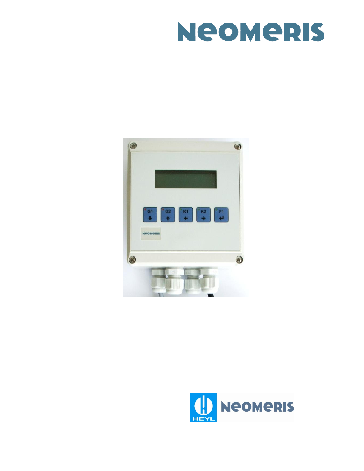
Conductivity Transmitter D200
Order codes:
D200 0-20/200/2000 µS/cm for wall mounting installation: 880204

D200 Description
Gebr. Heyl Vertriebsgesellschaft für innovative Wasseraufbereitung mbH 2
Table of contents
1.
Description.................................................................................3
2.
Technical Data...........................................................................3
3.
Dimensional drawings................................................................6
4.
Display, operation and front side settings..................................7
5.
Back side settings and terminal connections.............................9
6.
Further operating conditions....................................................10
7.
Conductivity measuring cells for standard transmitters ...........11
8.
Product range HEYL-NEOMERIS and contact details ............14

D200 Description
Gebr. Heyl Vertriebsgesellschaft für innovative Wasseraufbereitung mbH 3
1. Description
Device for the measurement of the electrical conductivity of aqueous solutions using a two-electrode
conductivity cell. Designed for wall mounting installation.
Applications: Demineralisation, reverse osmosis, desalination, cooling water recirc., phase separation
Operation at 230 V AC or 24 V DC.
2 potential-free relays – changeover switch for limit values (5 % hysteresis – fixed setting).
Alphanumeric display with 2 x 16 digits.
Temperature measurement and display between 0.0 °C and 100.0 °C if using a Pt100.
Temperature compensation with 2.2 % / K at 90 °C; can be disengaged.
Temperature sensor is monitored for sensing element fracture (error message in display).
Reversible mode of action for relay outputs.
Analogue output for the measured conductivity value: 0 – 10 V and 4 – 20 mA.
2. Technical Data
Measuring ranges: 0 – 20 / 200 / 2000 µS/cm,
depending on measuring cell and amplification
Temperature compensation: Linear 2.2 % / K, can be disabled; Reference temperature 25 °C
Indication of limit values: Optical via 2 LEDs, 2 limit values can be set within
0 and 100 % of the measuring range
Limit value outputs: 2 potential-free relay contacts, max. 6 A / 250 V AC each
Analog outputs: 0-10 V, Ra > 1 kOhm and 4-20 mA, Ra < 500 Ohm;
corresponding to 0 – 20 / 200 / 2000 µS/cm
Power supply: 22 - 26 V DC, protected against voltage reversal, potential-separated,
1000 V isolation voltage; or 230 V 50/60 Hz
Power consumption: Approx. 3 W / 3 VA
Protection class: IP 65
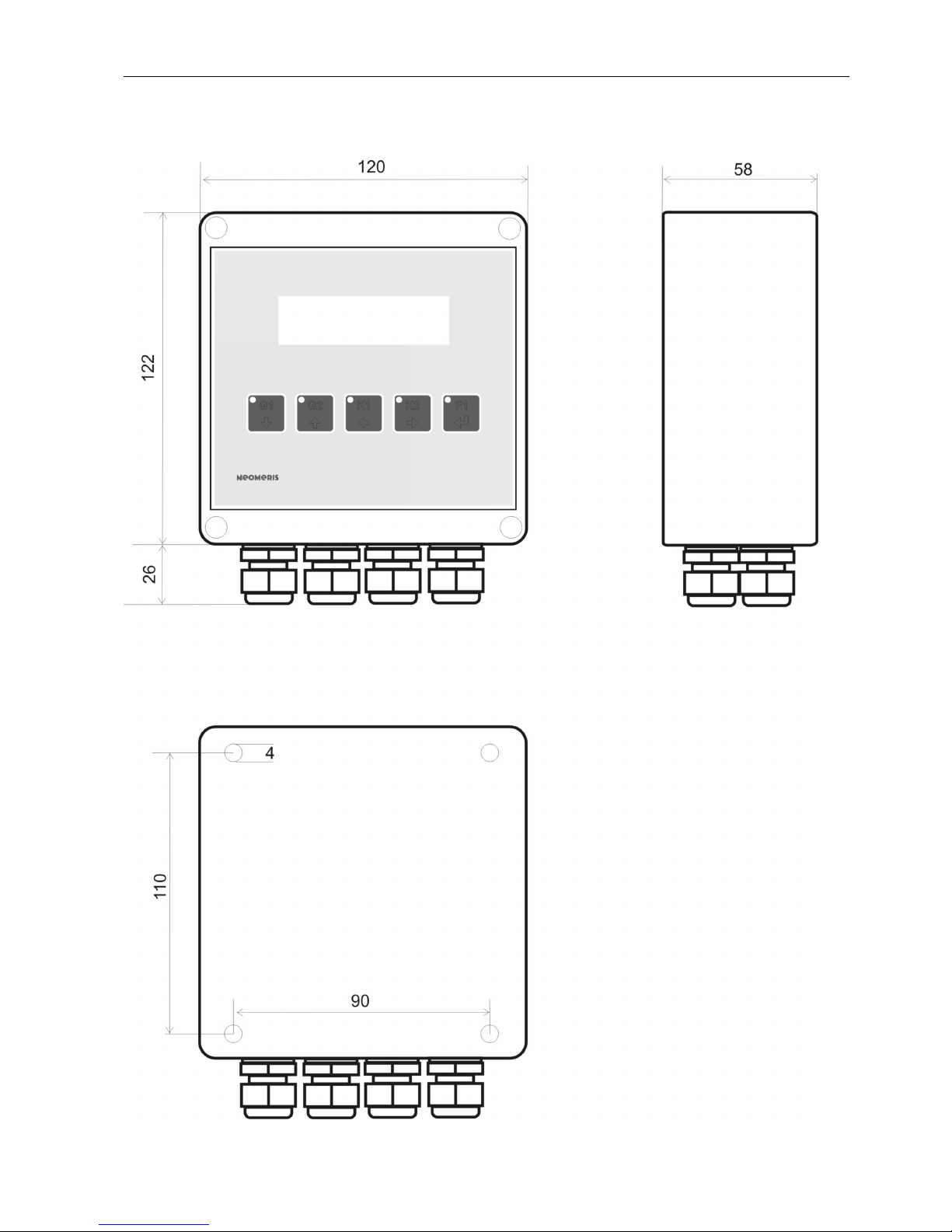
Housing: Wall mounting housing (Polycarbonate) 120 x 122 x 57 mm
Connections: 4 x PG9 cable glands at bottom side of housing

D200 Technical Data
Gebr. Heyl Vertriebsgesellschaft für innovative Wasseraufbereitung mbH 4

D200 Technical Data
Gebr. Heyl Vertriebsgesellschaft für innovative Wasseraufbereitung mbH 5
D200 Dimensional drawings
Gebr. Heyl Vertriebsgesellschaft für innovative Wasseraufbereitung mbH 6
3. Dimensional drawings

D200 Display, operation and front side settings
Gebr. Heyl Vertriebsgesellschaft für innovative Wasseraufbereitung mbH 7
4. Display, operation and front side settings
Display:
Display top line: Conductivity in µS/cm
Display bottom line:
Without temperature compensation: Limit values 1 and 2
With connected Pt100 sensor and enabled
temperature compensation: Sensor temperature or
actuating G1 or G2: Display of limit values 1 and 2 for 5 sec.
In case of fracture, disconnection or short-circuit of
Pt100 sensor
and enabled temperature compensation:
! T-Sensor !
Exceedance of the permitted measuring range: ! LF > MB !
LEDs:
F1 green Operation indicator, flashing in programming mode
K1 green Relay 1 triggered
K2 green Relay 2 triggered
G1 red Conductivity limit value 1 exceeded
G2 red Conductivity limit value 2 exceeded
D200 Display, operation and front side settings
Gebr. Heyl Vertriebsgesellschaft für innovative Wasseraufbereitung mbH 8
Relay settings:
The relay output modes of operation is switchable via DIP switch 6 at the back side (see chapter
Back side settings and terminal connections).
DIP switch position off (bottom):
Relays drop at limit value exceedance
DIP switch position on (top): Relays are triggered at limit value exceedance
K1 Manual control of relay 1 (The buttons for the relay control invert the respective
switching state for the actuation time.)
K2 Manual control of relay 2 (The buttons for the relay control invert the respective
switching state for the actuation time.)
Limit value settings:
Push buttons F1, G1 and G2 simultaneously for 3
sec. As a result the programming mode is active and
LED F1 flashes.
Push buttons F1 and G1 simultaneously, then
limit value 1 can be changed.
Push buttons F1 and G2 simultaneously, then
limit value 2 can be changed.
Approx. 5 seconds after the last activation both limit values are being saved and the adjustment
mode will be locked.
Both limit values can be adjusted to any value between 0 % and 100 % of the measuring range.
Calibration:
Zero point and measuring range of the instrument are pre-calibrated. A correction is normally not
necessary.

D200 Back side settings and terminal connections
Gebr. Heyl Vertriebsgesellschaft für innovative Wasseraufbereitung mbH 9
5. Back side settings and terminal connections
Terminal connections:
1 Shield Sensor cable shield
2 MG1 Conductivity measuring cell
3 MG1 Conductivity measuring cell
4 MG2 Pt100
5 MG2 Pt100
6 0-10 V Output 0 – 10 V
7 4-20 mA Output 4 – 20 mA
8 Ground Ground for outputs 0 – 10 V and 4 – 20 mA, respectively
9 K1 Ein Relay 1, Input, root
10 K1 Ö Relay 1, Break contact
11 K1 S Relay 1, Make contact
12 K2 Ein Relay 2, Input, root
13 K2 Ö Relay 2, Break contact
14 K2 S Relay 2, Make contact
15 24 V - Input 24 V DC, Ground
16 24 V + Input 24 V DC, +Pole
17 BR1 internally bridged to terminal 18, potential-free
18 BR1 internally bridged to terminal 17, potential-free
19 BR2 internally bridged to terminal 20, potential-free
20 BR2 internally bridged to terminal 19, potential-free
21 230 V AC Input 230 V AC
22 230 V AC Input 230 V AC
1 2 3 4 5 6 7 8 9 10 11 12 13 14 15 16 17 18 19 20 21 22
Temp. range
Temp. zero point
Cond. range
Cond. zero point

D200 Further operating conditions
Gebr. Heyl Vertriebsgesellschaft für innovative Wasseraufbereitung mbH 10
Potentiometer settings (all are pre-adjusted!):
Zero point conductivity measurement
Range conductivity measurement
Setting for temperature measuring at 0 °C (Pt 100 = 100.0 Ohm)
Setting for range, e.g. at 95 °C (Pt100 = 136.8 Ohm)
DIP switch settings: S1 S2 S3 S4 S5 S6 Sensor required
Measur. range 0 – 20 with TC off on on off off ** K = 0.1, Pt100
Measur. range 0 – 20 without TC off on on off on ** K = 0.1
Measur. range 0 – 200 with TC on off off on off ** K = 0.1, Pt100
Measur. range 0 – 200 without TC on off off on on ** K = 0.1
Measur. range 0 – 2000 with TC on off on on off ** K = 1.0, Pt100
Measur. range 0 – 2000 without TC on off on on on ** K = 1.0
For DIP switch position S5: ** For DIP switch position S6:
With Temp. compensation: bottom Relay triggered at conductivity < limit value: on
Without Temp. compensation: top Relay triggered at conductivity > limit value: off
Only one power supply connection is permitted; either 230 V AC or 24 V DC. The 24 V DC input
is protected against voltage reversal. AC voltage at the 24 V DC input oder DC voltage at the
230 V AC input destroy the instrument immediately and completely.
The measuring cell connection cable must be a shielded type for usage in industrial
environments at lengths above 1 meter.
The terminals ground and shield are internally connected to the common housing ground
(Voltage isolation of 1000 V to the power transformer and to the 24 V DC connection,
respectively). Under no circumstances these terminals should be bridged to another terminal
or connected to an existing ground connection. Otherwise the potential isolation of
measuring cell and electronics will be overruled.
6. Further operating conditions
The operation of the measuring instrument above the permitted measuring range and constant
short-circuit, respectively, can lead to instrument damage!

D200 Conductivity measuring cells for standard transmitters
Gebr. Heyl Vertriebsgesellschaft für innovative Wasseraufbereitung mbH 11
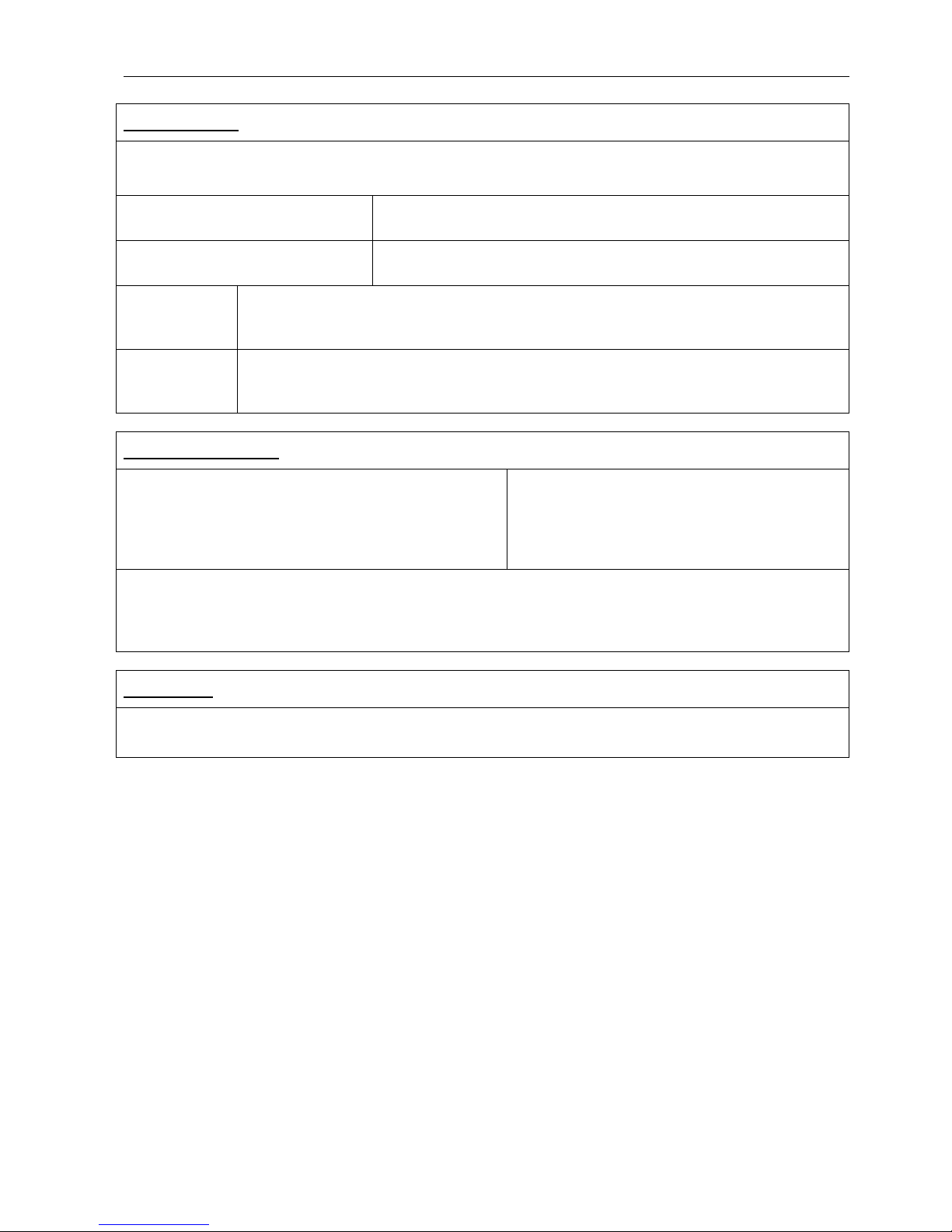
7. Conductivity measuring cells for standard transmitters
Conductivity measuring cells, ½“ and ¾“:
•Cell constant K: 0.1 or 1.0 (±5%), depending on type
•Electrode body material: PP (M101, M110, M201, M210) oder PVDF
(M401, M410)
•Electrode pin material: 1.4404
•Electrode pin sealing: NBR 70 (optionally EPDM / VITON; max. 130°C)
•Max. operating pressure: 6 bar
•Max. temperature: 80 °C
•Plug protection class: IP 65
•Temperature sensor Pt100: Optionally for M201, M210, M401, M410
(Pt1000 upon request)
•Immersion depth: Depending on type
Plug connections: 2 and = Electrodes 1 and 3 = Temperature sensor
Operation conditions: Sensors must be fully immersed.
½ M101 K=0
.
1
with
Screw-in
thread
½“
and
magnetic valve plug
880206
½ M110 K=1
.
0
with
Screw-in
thread
½“
and
magnetic valve plug
880207
¾ M201 K=0
.
1
with
Screw-in
thread
¾“
and
magnetic valve plug
880208
¾ M201
/ Pt100
K=0
.
1
with
Pt100
.
Screw-in thread
¾“
and magnetic valve
plug
880210
¾ M210 K=1
.
0
with
Screw-in
thread
¾“
and
magnetic valve plug
880209
½ M101
½
M110
¾
M201
D200 Conductivity measuring cells for standard transmitters
Gebr. Heyl Vertriebsgesellschaft für innovative Wasseraufbereitung mbH 12
¾ M210
/ Pt100
K=1
.
0
with
Pt100
.
Screw-in thread
¾“
and magnetic valve
plug
880211
½ M401 K=0
.
1
with
Screw-in
thread
½“
and
magnetic valve plug
880262
½ M401
/ Pt100
K=0
.
1
with
Pt100
.
Screw-in thread
½“
and magnetic valve
plug
880263
½ M410 K=1
.
0
with
Screw-in
thread
½“
and
magnetic valve plug
880264
½ M410
/ Pt100
K=1
.
0
with
Pt100
.
Screw-in thread
½“
and magnetic valve
plug
880265
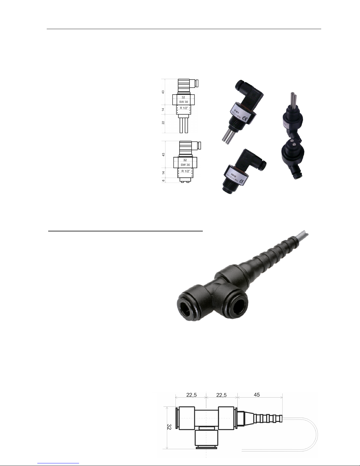
Conductivity measuring cell M301, John Guest 8 mm:
•Cell constant K: 0.1 (± 5 %)
•Electrode body material: POM
•Electrode pin material: 1.4404
•Max. operating pressure: 6 bar
•Max. temperature: 60 °C
•Without temperature sensor
Electrical connection:
brown: Electrode, Outer sheath
white: Electrode, inside
blue: Shield
Water connection:
John Guest – 8 mm
Inlet preferably at bottom, and outlet in lateral position.
Including safety clips for protection against accidental removal.
M301 K=0
.
1 in John
Guest T-piece
PM0208E
with
3m
fixed cable
880212
¾ M210 / Pt100
½
M401
½
M4
10
M301
D200 Conductivity measuring cells for standard transmitters
Gebr. Heyl Vertriebsgesellschaft für innovative Wasseraufbereitung mbH 13
Combinations overview: Conductivity measuring cells and transmitters
* only with external measuring cell. ** not with M301
References overview: Conductivity measuring cells
½ M101 K=0
.
1
with
Screw-in thread
½“
and magnetic valve plug
880206
½ M110 K=1
.
0
with
Screw-in thread
½“
and magnetic valve plug
880207
¾ M201 K=0
.
1
with
Screw-in thread
¾“
and magnetic valve plug
880208
¾ M201 / Pt100 K=0
.
1
with
Pt100
.
Screw-in thread
¾“
and magnetic valve plug
880210
¾ M210 K=1
.
0
with
Screw-in thread
¾“
and magnetic valve plug
880209
¾ M210 / Pt100 K=1
.
0
with
Pt100
.
Screw-in thread
¾“
and magnetic valve plug
880211
½ M401 K=0
.
1
with
Screw-in thread
½“
and magnetic valve plug
880262
½ M401 / Pt100 K=0
.
1
with
Pt100
.
Screw-in thread
½“
and magnetic valve plug
880263
½ M410 K=1
.
0
with
Screw-in thread
½“
and magnetic valve plug
880264
½ M410 / Pt100 K=1
.
0
with
Pt100
.
Screw-in thread
½“
and magnetic valve plug
880265
M301 K=0
.
1 in John Guest T-piece PM0208E
with
3m fixed cable 880212
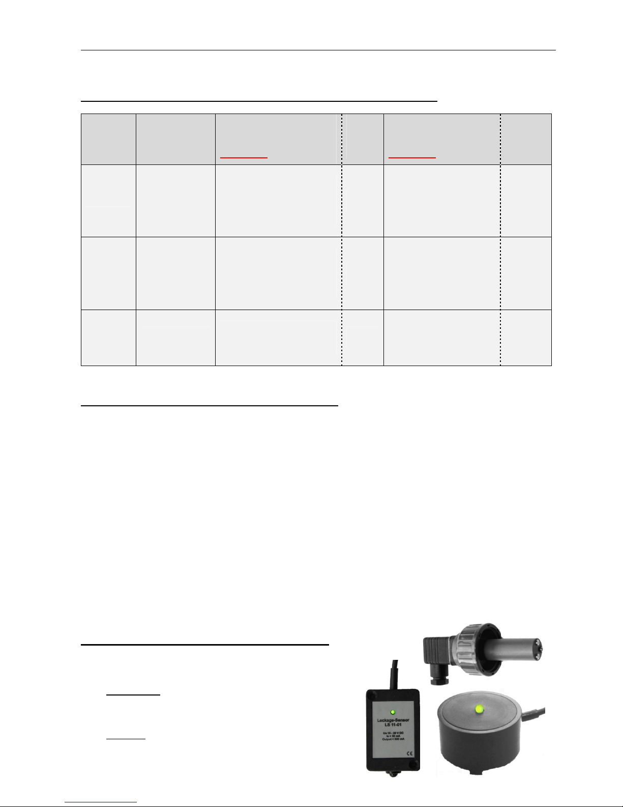
Special designs and leak detectors upon request:
- For example conductivity cells with screw connection:
- Leak detectors:
Applications: Detection of liquid leakages in building
services engineering, archives, large-scale IT facilities,
emergency power systems, hydraulic systems,
laboratories, etc.
Function: Infrared spot detector. Works with any liquid
Cell
constant
(± 5 %)
For
measuring
range
Measuring Reference
cell
with Pt100
For
Instru
ments
Measuring Reference
cell
with Pt100
For
Instru
ments
0.1 0 – 20 µS/cm
(0-10: D10)
¾ M201 / Pt100 880210
½ M401 / Pt100 880263
D200
D300
½ M101 880206
¾ M201 880208
M301 880212
½ M401 880262
LED5*
D10*
/
**
D200
D300
0.1 0 – 200 µS/cm
(0-100: D100)
¾ M201 / Pt100 880210
½ M401 / Pt100 880263
D200
D300
½ M101 880206
¾ M201 880208
M301 880212
½ M401 880262
D100*
/
**
D200
D300
1.0 0 – 2000 µS/cm
(0-1000: D1000)
¾ M210 / Pt100 880211
½ M410 / Pt100 880265 D200
D300
½ M110 880207
¾ M210 880209
½ M410 880264
D1000*
/
**
D200
D300
D200 Product range HEYL-NEOMERIS and contact details
Gebr. Heyl Vertriebsgesellschaft für innovative Wasseraufbereitung mbH 14
and reacts already at thin films. Does not depend on
conductivity, consistency or draught in the environment.
8. Product range HEYL-NEOMERIS and contact details
ONLINE ANALYSIS TESTOMAT® Instruments, TITROMAT® Instruments
INSTRUMENTS Accessories and spares TESTOMAT®-/ TITROMAT®-Instuments
Reagents TESTOMAT®-/TITROMAT®-Instruments, Reagents BOB Instruments
CONTROLLERS Controllers-MMP for Softening Plants
Controller MMP 83 for Softening Plants
Controller ROE Mini for Reverse-Osmosis-Plants
Controllers-ROE for Reverse-Osmosis-Plants
Controllers MVE / MVD for Full-Demineralisation
Controllers for Cooling Circuits and Air Washers
Desalination Plates with Controller MSK 101
Pilot Distributors
Accessories SOFTMASTER®
PROCESS MEASURING Process Measuring Instruments for Conductivity, pH and Redox
INSTRUMENTS Conductivity Probes
Accessories
Neomeris Conductivity Measuring Instruments & Cells
Remote Control SOFTMASTER® / EcoControl
ANALYSIS SYSTEMS Multi-Parameter Handheld Photometer, Industry Solutions for Boiler House / Cooling
Tower, Swimming Pools / Disinfection, Reverse Osmosis Measuring Parameters
Analysis Sets
DUROGNOST® Limit Value Test Kits
DUROVAL® Titration Kits
TESTOVAL® Colorimetric Test Kits
Bioresin®
Accessories Chemicals
UV-TECHNOLOGY UV-Systems STANDARD
UV-Systems FOODSTUFF
UV-Systems PHARMA
UV-Systems for DRINKING WATER DISINFECTION
UV-Systems for TOC Destruction
Medium Pressure UV-Systems for Swimming Pool
UV-Monitoring Units and Accessories
OZONE-TECHNOLOGY Ozone Generator Systems for Swimming Pools
Ozone Generators for Laboratory, Industry and Water Treatment
Electrolytic Ozone Generators for Pure Water Disinfection
Ozone Measuring Equipment
Residual Ozone Destructors
Accessories for Ozone Generators
MEASURING TECHNOLOGY DEPOSENS® Biofilm Online Measuring System
Gebr. Heyl Vertriebsgesellschaft für
innovative Wasseraufbereitung mbH
Montoirestr. 6
31135 Hildesheim, Deutschland
Tel: +49 (0) 5121 7609-0
Fax: +49 (0) 5121 7609-44
Internet: www.heyl-vertrieb.de
Table of contents
Popular Transmitter manuals by other brands


Badger Meter
Badger Meter Recordall RET Installation & operation manual

Spektrum
Spektrum DX5e quick start guide

RKI Instruments
RKI Instruments 65-2641RK-05-04 Operator's manual

ADN pesage
ADN pesage T200F Series Installation and user manual

Orno
Orno OR-SH-1753 quick guide

KROHNE
KROHNE OPTIBAR DP 7060 Supplementary instructions


