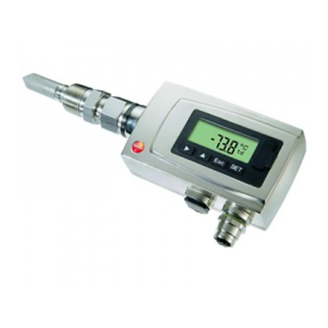
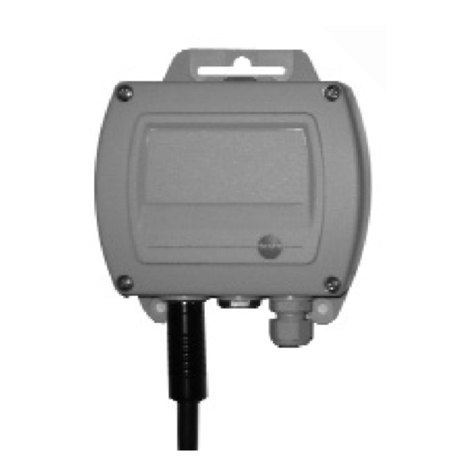
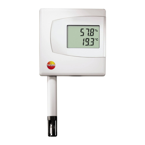
TESTO 6740 User manual

Instruction manual
testo 6740
GB

Preface/Copyright
2General information 3
Preface/Copyright
Preface
Dear Testo Customer
Congratulations for choosing a Testo product. We hope that you will enjoy many years
of using the product and that it will help you in your work.
If problems should occur which you cannot rectify yourself, please consult our service
department or your dealer. We will endeavour to provide fast and competent assistance
to save you long periods out of operation.
Copyright
This documentation is subject to the copyright of Testo AG. Reproduction and
employment contrary to the justified interests of Testo AG are prohibited without the
prior, written consent of the company.
We reserve the right to modify technical details from the descriptions, specifications and
illustrations contained in this documentation.
testo AAG
Postfach 11 40
79849 Lenzkirch
Germany
General information
This Instruction manual contains important information about the features and use of the
product. Please read this document through carefully and familiarise yourself with the
operation of the product before putting it to use. Keep the Instruction manual to hand so
that you can refer to it when necessary.
Pictograms
This product could be dangerous if operated incorrectly. Information that requires
particular attention is identified in this Instruction manual by pictograms:
Warnings are identified by means of a warning triangle. The relevant signal wword!
indicates the degree of risk:
Warning! means: Serious physical injury could occur if you do not take
the precautionary measures indicated.
Caution! means: Slight physical injury or material damage could occur if
you do not take the precautionary measures indicated.
Pay particular attention to warnings and take the precautionary measures
indicated in order to avoid danger.
Notes on special cases and peculiarities in the handling of the product are indicated
by an exclamation mark.
Standards/Approvals
According to the conformity certificate, this product fulfills all
89/336/EEC guidelines.
Signal wword!

1. Basic safety information 5
1. Basic safety information
Avoid electrical hazards:
Never take measurements with the instrument and its probes on or near live
components unless the instrument is expressly approved for current and voltage
measurements.
Protect the instrument:
Never store the unit together with solvents (e.g. acetone).
Preserving product safety/warranty entitlement:
Operate the instrument only within the parameters specified in the Technical data.
Handle the instrument appropriately and according to its intended purpose.
Never apply force!
Temperature data on sensors/probes refer only to the measurement range of the
sensors. Do not subject handles and lines to temperatures greater than 70°C if they
are not expressly approved for higher temperatures.
Open the instrument for maintenance and repair purposes only if specifically
described in the Instruction Manual.
Maintenance work should only be carried out if described in the Instruction Manual.
Please adhere to the steps described. For safety reasons, please only use spare
parts from Testo.
Any additional work should only be carried out by authorised trained personnel.
Otherwise Testo does not accept responsibility for the functioning of the instrument
following maintenance and for the validity of approvals.
Dispose of carefully:
Dispose of defect rechargeable batteries as well as empty batteries responsibly.
Once its service life has come to an end, return the instrument to us and we will
dispose of it.
Contents
4
Contents
Preface/Copyright ....................................................2
General information ..................................................3
Contents....................................................................4
1. Basic safety information ............................................5
2. Intended use ............................................................6
3. Product description ..................................................7
3.1 System components ................................................7
3.2 Operating elements ..................................................7
3.3 Settings ..................................................................8
4. Initial operation ..........................................................9
4.1 Mechanical assembly ..............................................9
4.2 Electric connection ..............................................10
4.3 Analog output/ Limit signal outputs ........................12
5. Menu guide (0555.6743 /0555.6744 only) ..............14
6. Adjustment on site ..................................................16
7. Care and maintenance ............................................17
8. Troubleshooting ......................................................18
9. Technical data ........................................................19
9.1 Measurement ranges and accuracies ....................19
9.2 Additional instrument data ....................................19
10. Accessories /Spare parts ........................................20
Warranty ................................................................21
Customer service/Calibration service ......................22
Notes ......................................................................23
Testo worldwide ......................................................26

3. Product description
3.1 System components 7
2. Intended use
6
3. Product description
3.1 System components
To
process
Cooling
coil 1
0554.3304
Measurement
chamber 22
0554.3303
G½, without display
0555.6741
NPT½“, without display
0555.6742
G½, with display
0555.6743
NPT½“, with display
0555.6744
Standard plug, 4 to 20mA
(included with all instruments)
Accessories:
0554.3302 plug (4 to 20mA,
2 switch contacts, 2 LEDs)
1Only required for process
temperatures > 50°C, cooling coil
only in connection with measurement
chamber
2Measurement chamber only required
if
- incoming flow is to be increased
(measurement chamber guarantees
a minimum incoming flow of 1l/min
at a positive pressure of 6bar).
- fast assembly/dismantling of
transmitter without interrupting
process is required.
To
PLC/control/
analysis unit
3.2 Operating elements
The instruments with the article numbers 0555.6741
and 0555.6742 do not have any additional operating
elements.
The instruments with the article numbers 0555.6743
and 0555.6744 have a keypad and a display to input
and read off settings (See 5. Menu guide, p. 12).
Standard quick-release device
G½ thread
Max. positive pressure: 15bar
Max. overpressure: 50bar
2. Intended use
The instrument is intended for use in the following applications:
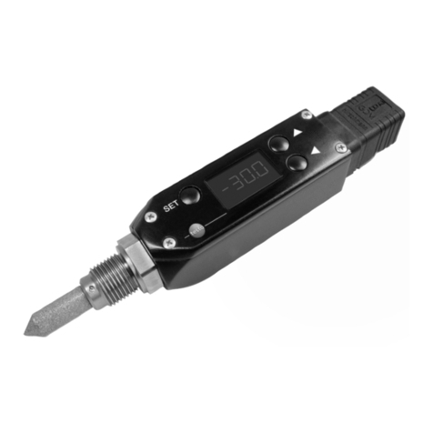
The testo 6740 instrument is a pressure dew point transmitter for measuring trace
humidity. It is used in the following areas:
- Monitoring trace humidity in compressed air systems and gas networks
(e.g. pipeline and container drying).
- Controlling and monitoring (compressed air) driers.
- Monitoring compressed air humidity in vehicles.
- Monitoring humidity and temperature in medical compressed air or
granulate driers.

4. Initial operation
4.1 Mechanical assembly 9
3.3 Settings
The parameters in the instrument are assigned the
following values in the factory:
3. Product description
3.3 Settings
8
Parameter Pressure dew point 1Atmospheric dew point 1Relative humidity Temperature Absolute humidity
Unit °Ctp °Ftp °CtA °FtA %rF, %rh, %Hr °C °F ppmvmg/m3(Abs)
4mA -60 -75 -60 -75 0 0 32 0 0
20mA 30 85 30 85 100 50 120 30000 230000 2
LS 4 40 4 40 30 10 50 8400 7000
US 12 55 12 55 50 30 85 13000 9600
1With dew point temperatures <0°Ctp /<0°CtA/<32°Ftp/<32°FtA the frostpoint temperature (dewpoint upon ice)
is displayed
2Display is shown to the power of ten: 30E3 (corresponds to 30 x 103= 30 x 1000 = 30000)
4.1 Mechanical assembly
We recommend you wrap the thread of the process
connection in sealing tape (e.g. Teflon) or place it in a
copper gasket (inner diameter: 21mm).
Force should only be applied to the Allen screw .
There are 3 different options for assembly depending
on the application:
Without measurement chamber and cooling coil
Compressed air!
Risk of injury!
Depressurise pipe sections (e.g. compressor
off or use bypass) and aerate before opening.
1Screw process connection (G½ or NPT½“) into the
matching thread.
The housing can be rotated by 350°. Do not use force
when aligning.
2Set up housing so that the display can be easily
read.
3Complete aeration of pipe section and apply
pressure to pipe section.
4. Initial operation
Assembly Application
Without measurement chamber - Process temperatures 0 to 50°C
and cooling coil - It is possible to attach sensor directly in process
- No quick assembly/dismantling of testo 6740 required and
flow on sensor is sufficient (1l/min)
With measurement chamber - Process temperatures 0 to 50°C
- Fast assembly/dismantling of testo 6740 required and/or
flow on sensor is insufficient (1l/min)
With measurement chamber - Process temperatures 50 to 200°C
and cooling coil
Warning

4. Initial operation
4.2 Electric connection 11
4. Initial operation
4.1 Mechanical assembly
10
With measurement chamber (max. 15bar)
1Screw in process connection (G½) of the
testo 6741/ 6743 transmitter in measurement
chamber thread.
2Snap quick-release lock of measurement chamber
in standard socket of compressed air line.
With measurement chamber and cooling coil
(max. 15bar)
1Screw in process connection (G½) of testo 6741/
6743 transmitter into thread of measurement
chamber.
2Snap quick-release lock of measurement chamber
in the quick-release lock of the cooling coil.
3Snap second quick-release lock of the cooling coil
into the standard socket of the compressed air line.
4.2 Electric connection
Standard plug
We recommend an 8 wire cable with a tightly braided
screen and a core cross-section of 0.2 to 0.5mm2.
1Loosen and remove screw at the back of the
plug and remove plug from transmitter .
2Remove plug socket from the plug housing. To do
this apply a small screwdriver to the point marked
with “lift“ and press out carefully .
3Screw on the cable positioning device and guide
the cables through the plug housing .
4Connect cable ends to the screw terminals of the
plug socket :
Plug socket terminals
1: + (4 to 20mA), power: 12...30VDC
2: - (4 to 20mA)
3: Not assigned
4: Measuring earth (cable screen)
1
3
2
lliifftt
5Insert plug socket into plug housing again until it
snaps into place and screw on cable fixing unit.
6Attach plug to transmitter and secure with screw
.
0554.3302 plug (with 2 switch outputs)
We recommend an 8 wire cable with a tightly braided
screen.
1Loosen and remove screw at the back of the
plug and remove plug from transmitter .
2Tilt the cover of the plug housing at an angle and
remove .
3Remove plug socket from the front and the relay
board from the back out of the plug housing.
4Screw on cable positioning device and guide
cables through the plug housing.
5Connect cable ends to the screw terminals of the
relay board or the plug socket :
1 2 3 4 5 6
I+
Flexible lead of relay board
Screen
on PE
I-
1
3
2
Plug socket terminals
1: I + (4 to 20mA)
2: I - (4 to 20mA)
3: (connected to relay
board in factory)
: Put on screen
Relay board terminals
1: 20 to 28 VDC
2: LS+
3: LS-
4: US+
5: US-
6: 0VDC
Current
signal and
supply 20 to
28VDC
Plug
socket
Relay board
The supply lines need
to be galvanically
connected, so connect
either - or - !

4. Initial operation
4.3 Analog output/ Limit signal outputs 13
4. Initial operation
4.2 Electric connection
12
6Push plug socket and plug board into the plug
housing (pay attention to alignment) and close lid.
7Screw on cable positioning device.
8Attach plug to transmitter and screw into place
.
4.3 Analog output/ Limit signal
outputs
Standard plug/0554.3302 plug
Both plug variations have a 4 to 20mA analog output
available in two-wire technology.
Limit signal outputs with 0554.3302 plug
Two floating contacts (NO contact) are available.
LS
LS= On
LS= Off
US= On
US= Off
Switch contact closed
Switch contact open
TTrraacceehhuummiiddiittyy((ee..gg..aass
pprreessssuurreeddeewwppooiinntt,,
°°CCttppdd))
Switching point:
Lower Switch (LS),
default setting:
4°Ctpd
Switching point:
Upper Switch (US),
default setting:
12°Ctpd
}
}
Terminal 2
Terminal 3
US
Terminal 4
Terminal 5
MMaaxx..cciirrccuuiitt::
30VDC / 0.5A
RL
x
yPPoowweerr
Standard plug:
U = 12 to 30VDC
0554.3302 plug:
U = 20 to 28VDC
xx,,yyccoonnnneeccttiioonn::
Connection Standard 0554.3302
x Terminal 1 Terminal 1
y Terminal 2 Terminal 6
MMaaxx..llooaaddRRL((eexxtteerrnnaallllooaadd))::
U Standard 0554.3302
12V 50 Ohm -
24V 650 Ohm 650 Ohm
30V 950 Ohm - 4 to 20mA
HHYYSStt, default
setting: 2K HHYYSStt

1514 5. Menu guide
Set lower operating point
(LS) 6
= +1
= Next digit
Set upper operating
point (US) 6
= +1
= Next digit
Set hysteresis value
(HYSt)
= +1
= Next digit
Test limit signal outputs
(tESt)
-0- = Both operating
points off
-1- = Lower operating
point on
-2- = Upper operating
point on
Select with
Activate with
Enter reference value
(rEF) 9
= +1
= Next digit
Carry out reset (rES)
nor = No reset
rS = Reset (return to
default setting))
Select using
Signs and symbols:
Press button briefly.
Keep button pressed for 2s.
Change menu using button specified.
Save input using and change menu oorr
change menu using without saving input.
Notes:
1If there are breaks in the input, the system returns automatically to
the display mode after approx. 1min.
2In the case of the units ppm and Abs (mg/m3), values are
displayed/entered to the power of ten. Examples:
15E1 corresponds to 15 x 10 = 150, 02E2 corresponds to
2 x 100 = 200, 21E3 corresponds to 21 x 1000 = 21000
3Keep button pressed (1s/ 3s /5s/ 10s, corresponding to setting
in , default setting: 5s).
4Only with deactivated code (can be set in Prog - UCod menu).
5Absolute pressure (can be set in Prog - Pres menu) is included in
the calculation for absolute humidity (Abs) and atmospheric dew
point (°Ctp/ °Ftp).
6For negative values: select “-“ at left digit position.
7To deactivate codes: Enter 0000.
8Can only be used together with the 0554.3302 plug.
9Menu is only available if one of the following units is set: °Ctp, °Ftp,
%rF, %Hr or %rh (can be set in Unit menu). Also see 6. Adjustment
on site, p. 16.
10 General password (always valid): 6810
ALAr 8AdJ rST
Return to ALAr
Return to AdJ
Return to rSt
Return to UNIT
5. Menu guide
5. Menu guide (0555.6743/0555.6744 only)
Set unit (Unit)
Pressure dew point °Ctp/
°Ftp, atm. dew point 5°CtA/
°FtA, rel. humidity %rF/%Hr/
%rh, absolute humidity
mg/m3(display: abs) 5/ppmv,
temperature °C, °F
Select with
Set 4mA value
(S-Lo) 2
Define lower limit of scale 6
= +1
= Next digit
Set 20mA (S-Hi) 2
Define upper limit of scale 6
= +1
= Next digit
Set delay menu query
(Pti)
1s / 3s / 5s / 10s
Select using
De/Activate (dS-1) “display
can be switched off”
ON = Display can be
switched off
OFF = Display cannot be
switched off
Select using
De/Activate (dS-
2)“Change value/unit”
ON = 6s value, 2s unit
OFF = Value continuously
Select using
Set absolute pressure in
bar (PrES)5
= +1
= Next digit
Test analog output
(AtES)
-- = No signal
4 = 4mA
12 = 12mA
20 = 20mA
Select using
Activate using
ProG
Display: Min. value (Lo)
Display: Max. value (Hi)
Set code (UCod) 7
= +1
= Next digit
Display mode 1,2
Reading and unit alternately / Reading continuously (see)
Unit
Return to Unit
Return to ProG
3
Display from (see)
CodE
Enter code 10
4 digit password, default
setting: 6810
= +1
= next digit
4

1716 7. Care and Maintenance
7. Care and Maintenance
Filter, measurement chamber, cooling coil
If process conditions are oily or dusty, the stainless
steel sintered filter should be cleaned and also the
measurement chamber and cooling coil should be
cleaned if used.
Unscrew/remove filter, measurement chamber and
cooling coil, purge with compressed air or place in
an ultrasonic bath.
Sensor cleaning
Unscrew the filter and rinse the sensor carefully
with water or ethanole. Let dry well.
6. Adjustment on site
One point adjustment by inputting one reference
value
Using one point adjustment, you can enter a reference
value for a working point (e.g. -10°Ctpd) specified by
you. In this way you will achieve a minimum
target/actual deviation from this working point.
As a reference, you will need a dew point mirror or a
reference measuring instrument (e.g. testo 400,
testo 650) with a pressure dew point probe.
The Adj menu in which the reference value is
entered is only available if one of the following units
is set: °Ctp, °Ftp, %rF, %Hr or %rh (See 5. Menu
guide, p. 14, Unit menu, Setting unit).
1Expose reference measuring instrument and
testo 6740 to identical, constant conditions and
await adjustment time.
2Measure reference value and compare with
testo 6740 reading.
3If there are deviations in the values, enter reference
value in Adj menu.

1918 9. Technical data
9.1 Measurement ranges and accuracies
9. Technical data
9.1 Measurement ranges and accuracies
Type of mreasurement Measurement range Accuracy
Pressure dew point -60 to +30°Ctpd ±1K at ±0°Ctp
temperature ±3K at -20°Ctp
(trace humidity) ±4K at -40°Ctp
(at 25°C)
atm. dew point -80 to -15°Ctd at 30barrel cf. pressure dew point temperature
-70 to +10°Ctd at 3barrel
-60 to +30°Ctd at 0barrel
Temperature ±0 to +50°C ±0.5K
9.2 Additional instrument data
Characteristic Values
Supply voltage 24VDC (standard plug: 12 to 30 VDC allowed, 0554.3302 plug: 20 to 28VDC allowed)
Max. load Standard plug: 12V: 50Ohm, 24V: 650Ohm, 30V: 950 Ohm
0554.3302 plug: 12V: not allowed, 24V: 650Ohm, 30V: not allowed
Ambient temperature -20 to +70°C
Storage/transport temperature -40 to +80°C
Protection classIP65 (with plug attached and cable connected)
Rotatability 350°
(display alignment)
Humidity sensor Testo humidity sensor with logged trace humidity-adjustment at -40°Ctp/6bar
Temperature sensor NTC
Sensor protection Stainless steel sintered cap
Pressure resistance -1barrel to +50barabs
Measurement chamber 0554.3303: max. 15barabs
Dimensions 199.5x 37x37 (with standard plug), 203.5x37x37 (with 0554.3302 plug)
Analog output
Signal 4 to 20mA, two-wire technology
Scaling Standard: 4 to 20mA = -60 to +30°Ctpd, with freely scalable display
Output parameters °Ctp, °Ftp, °CtA, °FtA, %RH, ppmv, mg/m3, °C, °F
Resolution 12bit
Accuracy ±40µA
Limit value outputs (optional, only with 0554.3302 plug)
Contacts 2 NO contacts, potential-free, max. circuit 30V/0.5A
Operating points: Standard: +4°Ctp/12°Ctp, freely programmable with display
8. Troubleshooting
8. Troubleshooting
Fault Possible causes Remedy
Analog output values - Incorrect scaling or unit Change scaling or unit in Unit menu
too low/too high
No signal - Connection interrupted Check cables
or
- Supply voltage too low Check power:
- Polarity incorrect Standard plug min. 12VDC
0554.3302 plug: min. 20VDC
Signal >21mA - Sensor defect (broken). Sensor must be replaced.
Contact your local distributor or
Testo´s Customer Service.
Singal <4mA - Sensor corroded Sensor must be replaced.
Contact your local distributor or
Testo´s Customer Service.
If the fault cannot be repaired by following the suggestions given in the above table,
please contact your local distributor or Testo`s Customer service department.
Warranty 21
10. Accessories/Spare parts
20
Warranty
Testo grants a warranty of 2 years from the date of the initial purchase for this product. The
warranty covers all material and manufacturer faults.
Faults occurring during the warranty time will be rectified by Testo AG, its authorised sales
subsidiaries or authorised dealers in accordance with the following conditions and without charge
for labour and material costs.
Either the defective components will be replaced with new spare parts or the entire product will be
replaced according to Testo`s estimation.
The following are excluded from the manufacturer’s warranty:
Wear parts (e.g. rechargeable batteries/batteries, printing mechanisms) and consumables (e.g.
printer paper).
- Damage caused by:
- use contrary to the intended purpose or failure to observe the instruction manual
and/or the safety instructions,
- lack of care, accidents or normal wear,
- external influences (e.g. damage during transport, damage caused by vibration,
excess heat, water, moisture or acids),
- use of unsuitable accessories.
This warranty expires if:
- the type or serial number of the product is changed, deleted, removed or made
illegible
- repairs or modifications are undertaken by third parties or unauthorised persons.
This warranty covers none of the following items:
- regular maintenance and repairs or the replacement of parts due to normal wear,
- the costs of packaging and transport,
- transport risks incurred directly or indirectly in connection with this warranty,
- the costs of repairs, adjustments or similar measures taken beyond the extent of this
warranty.
In the case of a warranty claim, consult your dealer or the sales subsidiary responsible for your
country. The addresses can be seen at www.testo.com.
Enclose a brief description of the fault and the purchase receipt, indicating the delivery and
purchase dates, together with the product. Please also give us your telephone number for any
inquiries.
Warranty repairs do not extend the period of warranty.
Further claims of any kind against Testo such as commercial transformation, price reduction or
compensation will not be processed.
Name Part no.
Basic instruments (incl. plug for analog signal output)
with process connection G1/2, without display 0555 6741
with process connection NPT1/2”, without display 0555 6742
with process connection G1/2, with display 0555 6743
with process connection NPT1/2”, with display 0555 6744
Accessories
Cable connection plug for power/analog output 4 to 20mA, with 2 floating switch contacts and 0554 3302
2 LEDs (limit signal output, alarm output)
Measurement chamber for optimum flow on humidity sensor, max. 15bar 0554 3303
Cooling coil for process temperatures above 50 °C (up to 200°C) 0554 3304
ISO calibration certificate for pressure dew point (-40° to 0°Ctp at 6bar), free choice of points 0520 0116
ISO calibration certificate for pressure dew point at -10°Ctp and -40°Ctp 0520 0136
10. Accessories/ Spare parts

Notes 23
Customer service/Calibration service
22
Please contact your nearest Testo office or distributor for more information.

Notes 25
Notes
24

27
Testo worldwide
26 Testo worldwide
MOROCCO
A.F.M.I.L. SARL
Belevedere-Casablanca
Tel. (22) 24 01 84
Fax (22) 24 01 8
NETHERLANDS
Testo B.V.
1314 BH Almere-Stad
Tel. (36) 5 48 0 00
Fax (36) 5 48 0 09
NEW ZEALAND
Eurotec Instruments Ltd.
Auckland
Tel. (9) 5 9 19 90
Fax (9) 5 25 33 34
NICARAGUA
Adolfo Gröber & Cía Ltda.
Managua
Tel. 2 66 51 36
Fax 2 66 51 39
NORWAY
Max Sievert A/S
0134 Oslo
Tel. (22) 1 30 85
Fax (22) 1 25 11
PERU
JJL Asociados S.A.
Lima 1
Tel. (1) 2 61 1 52
Fax (1) 2 61 46 0
PHILIPPINES
Keystone Industrial
Trading Corporation
Pasay City 1300,
Tel. (2) 8 31 95 1
Fax (2) 8 31 40 13
POLAND
Testo Sp. z.o.o.
02-362 Warszawa
Tel. (22) 8 63 4 22
Fax (22) 8 63 4 15
PORTUGAL
Testo Portugal Lda.
3830-23 Ribas (ILHAVO)
Tel. 2 34 08 3 11
Fax 2 34 08 3 08
ROMANIA
Test Line SRL
221 Bucharest
Tel. (21) 6 8 34 62
Fax (21) 2 42 68 24
SERBIA
YMC Laboratorija
1100 Belgrade
Tel. 11 316 2335
Fax 11 316 258
SINGAPORE / MALAYSIA /
INDONESIA
Futron Electronics PTE LTD
Singapore 329 14
Tel. (65) 62 50 24 56
Fax (65) 62 50 65 92
futron@cyberway.com.sg
SLOVAKIA
K - Test s.r.o.
042 60 Kosice
Tel. (1) 55 625 36 33
Fax (1) 55 625 36 33
SLOVENIA
Komplast d.o.o.
1356 Dobrova
Tel. (1) 5 44 11 30
Fax (1) 5 44 11 31
SOUTH AFRICA
Unitemp
Landsdowne, Cape Town,
9
Tel. (21) 62 89 95
Fax (21) 62 89 96
SPAIN
Instrumentos Testo S. A.
08348 Cabrils (Barcelona)
Tel. (93) 53 95 20
Fax (93) 53 95 26
SWEDEN
Nordtec Instrument
40241 Göteborg
Tel. (31) 04 10 0
Fax (31) 12 50 42
SWITZERLAND
Testo AG
8604 Volketswil
Tel. (1) 9 08 40 50
Fax (1) 9 08 40 51
SYRIA
Medical Business Center
Damascus
Tel. (11) 2 32 23 01
Fax (11) 2 32 23 02
TAIWAN, R.O.C.
Hot Instruments Co. Ltd.
Chungho City, 235
Tel. (2) 89 23 23 18
Fax (2) 89 23 23 1
THAILAND
Entech Associate Co. Ltd.
Bangkok 10210
Tel. (2) 9 54 54 99
Fax (2) 9 54 54 95
TUNISIA
Starepr
2000 Le Bardo
Tel. ( 1) 50 92 86
Fax ( 1) 58 49 20
TURKEY
Testo Elektronik ve Test Ölcüm
Cihazlari Dis Ticaret Ltd. STi
80290 Gayrettepe-Istanbul
Tel. (212) 2 1 01 55
Fax (212) 2 1 02 21
UNITED ARAB EMIRATES
Enviro engineering (W.L.L.)
General Trading
Dubai
Tel. (14) 2 2 0 20
Fax (14) 2 23 36 83
USA
Testo Inc.
Flanders, NJ. 0 836
Tel. (9 3) 2 52 1 20
Fax (9 3) 2 52 1 29
VENEZUELA
G & M International Service,
C. A.
San Antonio de los Altos,
Edo. Miranda
Tel. (2) 3 2 0
Fax (245) 5 1 6 4
gminter@cantv.net
Sermatic srl
Carabobo
Tel. (45) 1 36 35
Fax (45) 1 36 35
nugece@cantv.net
VIETNAM
MTC
Measuring and Testing
Equipment Company Ltd.
Hanoi
Tel. (4) 33 36 36
Fax (4) 33 21 03
SMICO
Scientific Equipment &
Measuring and Testing
Hanoi
Tel. (4) 8 53 26 92
Fax (4) 5 63 36
Stand 03.06.2003
Stets aktualisierte Adressdaten
unserer Töchter und Landes-
Vertriebspartner finden Sie im
Internet unter: www.testo.com
03.06.2003
The most up-to-date address
details of our subsidiaries and
agencies can be found in
Internet at: www.testo.com
ALGERIA
SNC COVAM
Bejaia 06000
Tel.: 34 20 6 23
Fax 34 20 6 23
covam_berri@yahoo.fr
ARGENTINA
Testo Argentina S.A.
C1440ACR - Buenos Aires
Tel. (11) 46 83 - 50 50
Fax (11) 46 83 - 50 50
ASIA
Testo (Asia) Ltd.
Shatin, N. T., Hong Kong
Tel. (2) 26 36 38 00
Fax (2) 26 4 23 39
AUSTRALIA
Testo Pty. Ltd.
Wantirna 3152
Tel. (3) 98 00 43 99
Fax (3) 98 00 46 99
AUSTRIA
Testo Ges. mbH
11 0 Wien
Tel. (1) 4 86 26 11- 0
Fax (1) 4 86 26 11 20
BELGIUM / LUXEMBURG
S. A. Testo N. V.
1 41 Ternat
Tel. (2) 5 82 03 61
Fax (2) 5 82 62 13
BOLIVIA
T.E.C.
Cochabamba
Tel. (4) 4 40 09 1
Fax (4) 4 28 60 02
Helios SRL
Santa Cruz
Tel. (3) 49 26 03
Fax (3) 12 5 45
BOSNIA-HERZIGOWINA
Tehnounion Sarajevo
Sarajevo
Tel. (33) 20 59 44
Fax (33) 44 40 00
BRAZIL
Testo do Brazil
13028-015 Campinas - SP
Tel. (19) 3 31 - 58 00
Fax (19) 3 31 - 58 19
BULGARIA
Global Test OOD
1408 Sofia
Tel. (2) 9 53 0 96,
Fax (2) 9 52 51 95
CHILE
ANWO S.A
Santiago
Tel. (2) 31 00 00
Fax (2) 2 3 04 04
CHINA
Testo Instruments International
Trading (Shanghai) Co., Ltd.
Shanghai 200031
Tel. (21) 54 56 - 14 48
Fax (21) 54 56 - 14 0
CIS
Global Export GmbH
105 023 Moscow
Tel. (0 95) 3 60 53 68
Fax (0 95) 3 60 53 68
COLOMBIA
Arotec Colombiana S. A.
Bogota D. E.
Tel. (1) 2 88 99
Fax (1) 2 85 36 04
COSTA RICA
Representaciones
Corelsa S. A.
Santo Domingo de Heredia
Tel. 2 44 25 50
Fax 2 44 30 90
CROATIA
"H.I.P." Zagreb d.o.o.
10090 Zagreb
Tel. (1) 3 3 40 0
Fax (1) 3 3 40 44
CYPRUS
Deksa Ltd.
Nicosia
Tel. (2) 2 45 55 55
Fax (2) 2 49 0 59
CZECH REPUBLIC
Testo s.r.o.
158 00 Praha 5
Tel. (2) 5 29 02 05
Fax (2) 5 29 04 10
DENMARK
Buhl & Bonsoe A/S
2830 Virum
Tel. 45 95 04 10
Fax 45 95 04 12
EGYPT
Future Plants Contractors
Heliopolis 11361, Cairo
Tel. (2) 4 18 6 9
Fax (2) 4 18 95 04
EL SALVADOR
Eco Control S.A de C.V.
San Salvador
Tel. 2 60 66 01
Fax 2 60 66 02
eco.control@sv.intercomnet.net
FINLAND
Humitec Oy
00300 Helsinki
Tel. (9) 5 30 84 00
Fax (9) 53 08 40 99
FRANCE
testo Sàrl
5 602 Forbach
Tel. 3 8 29 29 00
Fax 3 8 8 40 9
GREECE
Sigma Hellas Ltd.
18536 Piraeus
Tel. (210) 4 52 2 45
Fax (210) 4 51 90 20
Sigma Hellas Ltd.
54644 Thessaloniki
Tel. (23 10) 98 80 40
Fax (23 10) 98 92 2
GREAT BRITAIN / IRELAND
Testo Ltd.
Alton, Hampshire GU34 2QJ
Tel. (14 20) 54 44 33
Fax (14 20) 54 44 34
HUNGARY
Testo Kft.
1139 Budapest
Tel. 23 1 4
Fax 23 1 48
ICELAND
Rafn Jensson, Mechanical
Engineers ehf
110 Reykjavik
Tel. 5 6 80 30
Fax 5 6 80 15
INDIA
Siskin Instruments Co. Ltd.
Bangalore 560 054
Tel. (80) 3 60 25 60
Fax (80) 3 60 36 9
WAAREE Instruments Ltd.
Mumbai 400 093
Tel. (22) 26 8 4 8
Fax (22) 26 8 36 13
IRAN
Mehr Kanaz Sanat Co.
Tehran
Tel. (21) 2 26 26 89
Fax (21) 2 22 3
ISRAEL
Manoraz Ltd.
Azur 58001
Tel. (3) 5 59 33 99
Fax (3) 5 58 44 95
ITALY
Testo S.p.A.
20019 Settimo Milanese (Mi)
Tel. (02) 3 35 19 - 1
Fax (02) 3 35 19 - 200
JAPAN
Testo K.K.
Yokohama 222-0033
Tel. (45) 4 6 22 88
Fax (45) 4 6 22
JORDAN
Al-Masar Technique Est.
Sahab 115-12
Tel. (6) 4 02 95 22
Fax (6) 4 02 35 64
KOREA (Republic of)
Testo (Korea) Ltd.
Seoul 150-102
Tel. (2) 26 2 2 00
Fax (2) 26 9 98 53
MALTA
Technoline Ltd.
Gzira GZR 06
Tel. (21) 34 23 66
Fax (21) 34 39 52
MACEDONIA
Pharmachem Skopje
1060 Skopje
Tel. (2) 33 11 93
Fax (2) 33 14 34
MEXICO
Grupo de Instrumentación y
Medición Industrial de México,
S.A. de C.V.
08920 Mexico, D.F.
Tel. (55) 56 34 04 02
Fax (55) 56 33 04 01

0971.6740/T/dr/08.03
Other manuals for 6740
1
Table of contents
Other TESTO Transmitter manuals
Popular Transmitter manuals by other brands

PCB Piezotronics
PCB Piezotronics 682B03 Installation and operating manual

Absolute Process Instruments
Absolute Process Instruments APD 44 Series quick start guide

Nautel
Nautel ND500II-113-x21 manual

M-system
M-system B3VS/2 instruction manual

NIVELCO
NIVELCO NIPRESS D-700 Series user manual

Sony
Sony Walkman WLA-NWB1K operating instructions