LoRa Alliance MCF-LW13MIO User manual

2023/04/19 13:39 1/2 manual_mcf-lw13mio
e n g i n k o . s u p p o r t . c e n t e r - https://www.enginko.com/support/
Table of Contents
MCF-LW13MIO Operating Manual 1 ...............................................................................................
1. Description 1 ................................................................................................................................
2. Overview 2 ....................................................................................................................................
2.1 Technical data 2 .........................................................................................................................
2.2 Installation 3 ..............................................................................................................................
2.3 Power supply 4 ...........................................................................................................................
2.4 Configuration 5 ..........................................................................................................................
2.5 System leds 6 .............................................................................................................................
2.6 Firmware update 6 .....................................................................................................................
3 I/O 7 .................................................................................................................................................
3.1 Input 7 ........................................................................................................................................
3.2 Output 9 .....................................................................................................................................
4 LoRaWAN® network 11 ................................................................................................................
4.1 Activation 11 ..............................................................................................................................
5 Configuration 12 ............................................................................................................................
5.1 I/O settings 13 ............................................................................................................................
5.2 Other settings 14 .......................................................................................................................
5.3 Diagnostic 15 .............................................................................................................................
6 Passwords 15 .................................................................................................................................
7 Configuration file 16 .....................................................................................................................
7.1 Multi devices configuration 17 ...................................................................................................
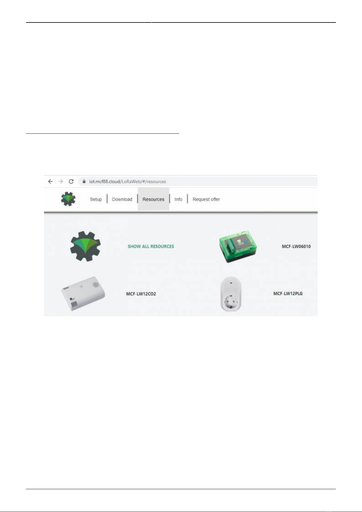
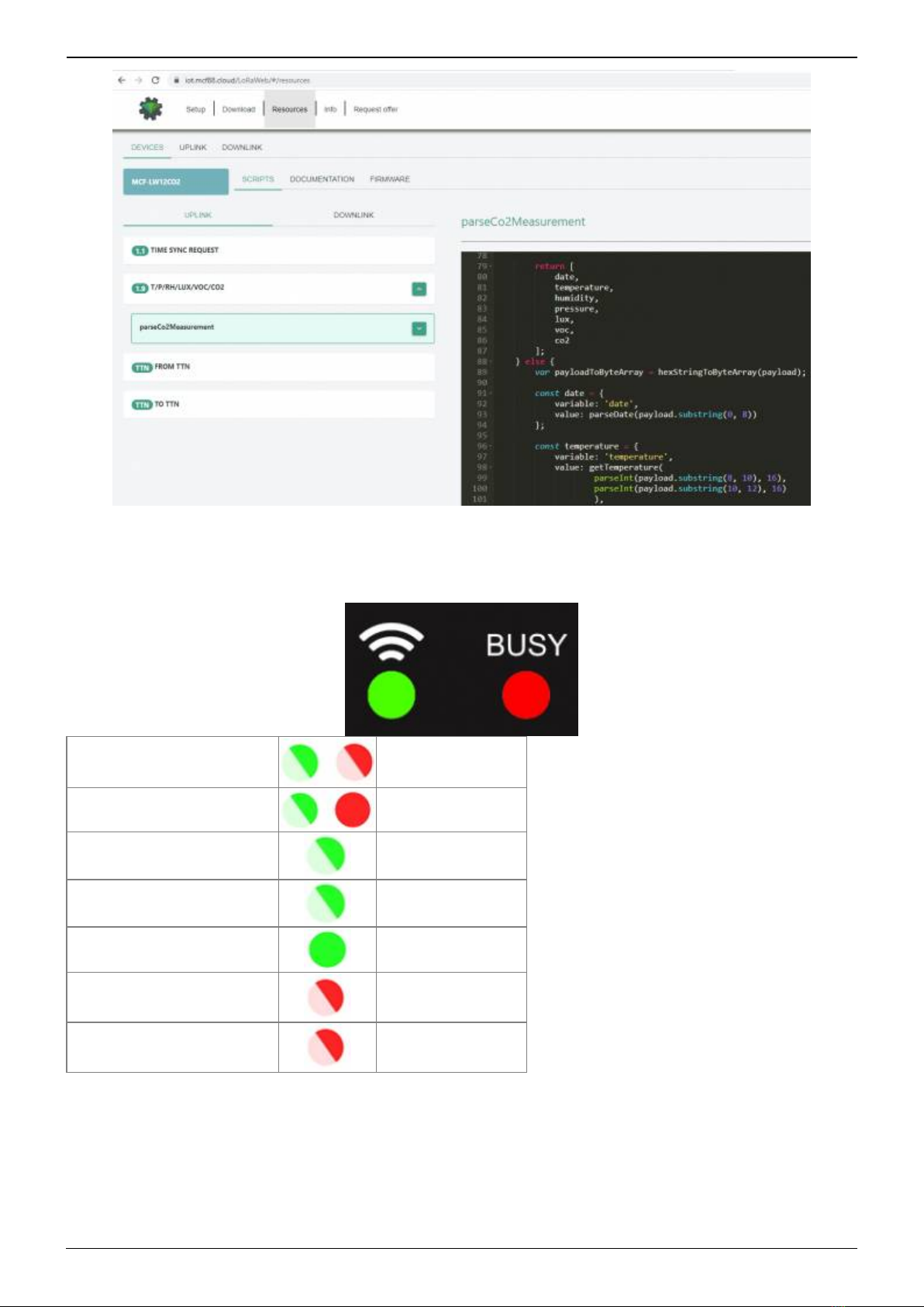
8 LoRaWEB Tool 18 ...........................................................................................................................
9 Payload 18 ......................................................................................................................................
10 Ordering code 19 ........................................................................................................................
11 Declaration of conformity 19 ....................................................................................................
12 Contacts 19 ..................................................................................................................................

Last update: 2023/04/17 08:30 manual_mcf-lw13mio https://www.enginko.com/support/doku.php?id=manual_mcf-lw13mio
https://www.enginko.com/support/ Printed on 2023/04/19 13:39

2023/04/19 13:39 1/19 manual_mcf-lw13mio
e n g i n k o . s u p p o r t . c e n t e r - https://www.enginko.com/support/
MCF-LW13MIO Operating Manual
Important safety information
Read this manual before attempting to install the device! Failure to observe
recommendations included in this manual may be dangerous or cause a violation of the
law. The manufacturer will not be held responsible for any loss or damage resulting from
not following the instructions of this operating manual.
Do not dismantle or modify in any way.
Avoid mechanical stress
Do not use any detergent or alcohol to clean the device.
Do not mount in horizontal position.
Disposal information for users
Pursuant to and in accordance with Article 14 of the Directive 2012/19/EU of the
European Parliament on waste electrical and electronic equipment (WEEE).
The barred symbol of the rubbish bin shown on the equipment indicates that, at the end of its useful
life, the product must be collected separately from other waste.
1. Description
This class C device transmits the state of its 16 inputs (12-24Vac/dc) and controls 8 outputs (5A -
230Vac) through the LoRaWAN® network. All these inputs and outputs are galvanically isolated. It
can be used for industrial process control, home automation, water treatment, agriculture irrigation
and similar applications.

Last update: 2023/04/17 08:30 manual_mcf-lw13mio https://www.enginko.com/support/doku.php?id=manual_mcf-lw13mio
https://www.enginko.com/support/ Printed on 2023/04/19 13:39
2. Overview
2.1 Technical data
CPU Cortex M0+
EEProm 32KB
Flash 96KB
Real time clock
Encryption AES 128 bit
Class C LoRaWAN® stack EU868, AS923, AU915, US915
EU868 version CE certified according to 2014/53/EU – Radio Equipment Directive (RED)
Transmission band (EU version): 868 MHz
Transmission Power (EU version): 14dBm max
Power supply 24Vac/dc
Maximum power consumption 8W
16 opto-isolated input AC-DC, range 5-24Vac/dc
8 relay output with COM, NO, NC contacts carrying 5Amp@230Vac~
USB for node setup ad FW upgrade
Storage temperature range -20°C ÷+80°C
Working temperature range -10°C ÷+70°C
DIN (EN 60715) mounting enclosure, 9 modules

2023/04/19 13:39 3/19 manual_mcf-lw13mio
e n g i n k o . s u p p o r t . c e n t e r - https://www.enginko.com/support/
2.2 Installation
The installation has to be done by a qualified electrician.
The device is intended as subassembly (component).
It is responsibility of the assembler of equipment incorporating to ensure that the overall equipment is
safe.
The MCF-LW13MIO must be mounted in vertical position.
2.2.1 Antenna
The magnetic antenna must be positioned on a metal body. It should preferably be vertical and at
least 30 cm away from other metal bodies. The installation must take place in a place where the
LoRaWAN® signal coverage is good (SF=7 optimal, SF=12 weak).

Last update: 2023/04/17 08:30 manual_mcf-lw13mio https://www.enginko.com/support/doku.php?id=manual_mcf-lw13mio
https://www.enginko.com/support/ Printed on 2023/04/19 13:39
2.3 Power supply
Name Description
VSS Vss reference, power supply dc (-)
VAC1 Power supply ac and dc (+)
VAC2 Power supply ac only
Valid range is 24Vac/dc ± 10%
Maximum power consumption: 8W
Connect the power supply to pins 11 and 12 of J3 if ac, pins 11 (+) and 10 (-) if dc.
Power can also be supplied by USB, only for configuration, not for normal use.
Dip Switches must be OFF.

2023/04/19 13:39 5/19 manual_mcf-lw13mio
e n g i n k o . s u p p o r t . c e n t e r - https://www.enginko.com/support/
2.4 Configuration
To deploy the sensor, use LoRaWEB online tool, to setup LoRaWAN® credentials and other
preferences (only available for Windows®) :
LoRaWEB Tool (iot.mcf88.cloud/LoRaWeb)
Before connect the device the first time, please install LoRaBridge applications and drivers:
https://iot.mcf88.cloud/LoRaWeb/#/download
Validate your settings reading data after the write.
enginko provides user manuals, javascript examples, downlink generator, uplink decoder, different
tools and, upon free registration, firmware updates :

Last update: 2023/04/17 08:30 manual_mcf-lw13mio https://www.enginko.com/support/doku.php?id=manual_mcf-lw13mio
https://www.enginko.com/support/ Printed on 2023/04/19 13:39
2.5 System leds
LoRaWAN® not configured Slow flashing
Joining Quick flashing
Sending Quick flashing
Receiving Quick flashing
Steady state Fixed
Data error Flashing 2 seconds
Connection error Flashing 1 second
2.6 Firmware update
Save the new firmware file (.exe) on the PC, run the file, select the USB FW port and start the update:

2023/04/19 13:39 7/19 manual_mcf-lw13mio
e n g i n k o . s u p p o r t . c e n t e r - https://www.enginko.com/support/
and waiting for the end message.
3 I/O
As default, the device sends a message every time an input or an output changes.
A downlink with new output status forces the device to send back an unplink with the new status. If
the output status is the same of current one, the sensor will not send back any message.
Downlink examples (hex):
turn ON the output 1: 0400 0100 0000 0000 0000
turn off the output 1: 0400 0000 0000 0100 0000
receive the current status: 0400 0000 0000 0000 0000
Is possible to set a period (in minutes) to receive a recurrent periodic message with the I/O status.
3.1 Input
Off voltage 0÷2Vac/dc
On Voltage >5Vac/dc
Maximum input voltage 28Vac/dc
Input current 5mA typ
Max frequency (as counter) 2Hz
Optoinsulation 2500Vac (1 min)
In case of DC input, the positive terminal must be connected to the positive input.

Last update: 2023/04/17 08:30 manual_mcf-lw13mio https://www.enginko.com/support/doku.php?id=manual_mcf-lw13mio
https://www.enginko.com/support/ Printed on 2023/04/19 13:39
Connector Pin Name Description
J1
1 I+1 Digital input 1 positive
2 I-1 Digital input 1 negative
3 I+2 Digital input 2 positive
4 I-2 Digital input 2 negative
5 I+3 Digital input 3 positive
6 I-3 Digital input 3 negative
7 I+4 Digital input 4 positive
8 I-4 Digital input 4 negative
9 I+5 Digital input 5 positive
10 I-5 Digital input 5 negative
11 I+6 Digital input 6 positive
12 I-6 Digital input 6 negative
Connector Pin Name Description
J2
1 I+7 Digital input 7 positive
2 I-7 Digital input 7 negative
3 I+8 Digital input 8 positive
4 I-8 Digital input 8 negative
5 I+9 Digital input 9 positive
6 I-9 Digital input 9 negative
7 I+10 Digital input 10 positive
8 I-10 Digital input 10 negative
9 I+11 Digital input 11 positive
10 I-11 Digital input 11 negative
11 I+12 Digital input 12 positive
12 I-12 Digital input 12 negative
Connector Pin Name Description
J3
1 I+13 Digital input 13 positive
2 I-13 Digital input 13 negative
3 I+14 Digital input 14 positive
4 I-14 Digital input 14 negative
5 I+15 Digital input 15 positive
6 I-15 Digital input 15 negative
7 I+16 Digital input 16 positive
8 I-16 Digital input 16 negative
Input can be used as pulse counters (see settings chapter).

2023/04/19 13:39 9/19 manual_mcf-lw13mio
e n g i n k o . s u p p o r t . c e n t e r - https://www.enginko.com/support/
3.2 Output
Contact mode SPDT
Max. power commutable 1250VA
Maximum switching voltage 250Vac~
Minimum switching load mW 500mW (10V/5mA)
Min. Number of operation 100.000
Max. current 5A
If driving an inductive load in AC, a Snubber must be provided in parallel to the
contacts formed by a RC resistance network = 100Ohm 2w in series with a 100nF
400Volt polyester capacitor. In the case of a DC-controlled load, an anti-parallel diode
must be placed on the load (ex. 1N4007). Each line must be protected with a suitable fuse
(FUSE).
Connector Pin Name Description
J4
1 NC_1 Normally closed 1
2 COM_1 Common output 1
3 NO_1 Normally open 1
4 NC_2 Normally closed 2
5 COM_2 Common output 2
6 NO_2 Normally open 2
7 NC_3 Normally closed 3
8 COM3 Common output 3
9 NO_3 Normally open 3

Last update: 2023/04/17 08:30 manual_mcf-lw13mio https://www.enginko.com/support/doku.php?id=manual_mcf-lw13mio
https://www.enginko.com/support/ Printed on 2023/04/19 13:39
Connector Pin Name Description
J5
1 NC_4 Normally closed 4
2 COM_4 Common output 4
3 NO_4 Normally open 4
4 NC_5 Normally closed 5
5 COM_5 Common output 5
6 NO_5 Normally open 5
7 NC_6 Normally closed 6
8 COM6 Common output 6
9 NO_6 Normally open 6
Connector Pin Name Description
J6
1 NC_7 Normally closed 7
2 COM_7 Common output 7
3 NO_7 Normally open 7
4 NC_8 Normally closed 8
5 COM_8 Common output 8
6 NO_8 Normally open 8
The output has pulse capability (minimum pulse duration is 100ms, maximum around 100
minutes), so, instead to send two different commands (one to turn on and one to turn off the
ouput), is possible to send a duration command.
As application example, to safely turn on an output, send a ON-pulse command for a defined time (for
example, for the maximum allowed interval), and before the expiring time, another ON-pulse
command (making a kind of watchdog) if the output still needs to be ON, or a simply OFF command if
you want to turn it off.
3.2.1 Time schedule
It is possible to program the device with a weekly calendar, based on day of the week and time, to
turn ON and OFF the output at a defined time:

2023/04/19 13:39 11/19 manual_mcf-lw13mio
e n g i n k o . s u p p o r t . c e n t e r - https://www.enginko.com/support/
and generate and XLS file that can be downloaded by downlinks:
4 LoRaWAN® network
The sensor is compliant with LoRaWAN® specification 1.0.2, regional 1.0.2b.
4.1 Activation
The device supports the following activations on a LoRaWAN® network:
NONE: sensor not activated1.
OTAA: the JoinEUI and the AppKey not setted, must be written to the device;2.
OTAA MCF88: Over the air activation, fixed keys: JoinEUI = 904e915000000003, AppKey on3.
request;
OTAA ENGINKO: Over the air activation, fixed keys: JoinEUI = 904e915000000003, AppKey on4.
request;
ABP: requires writing to the device of NwkSkey, AppSkey, DevAddr.5.

Last update: 2023/04/17 08:30 manual_mcf-lw13mio https://www.enginko.com/support/doku.php?id=manual_mcf-lw13mio
https://www.enginko.com/support/ Printed on 2023/04/19 13:39
The device exits factory activated with NONE mode. On request devices can be shipped aleady
activated.
Note: in OTAA AppKey is write only, in reading the field will always be empty, even if set.
Network settings:
please keep “Any” settings. Change it only if Objenious network is used (default_ any).
Network type:
LoRa syncword can be setted as “private”(0x12) instead “public” (0x34), but the NS must be setted
accordingly (default: public).
LoRa Band:
select the right LoRaWAN ® band settings accodingly to country requirements.
5 Configuration

2023/04/19 13:39 13/19 manual_mcf-lw13mio
e n g i n k o . s u p p o r t . c e n t e r - https://www.enginko.com/support/
5.1 I/O settings
Status of the output at power on:
select the status of OUTPUT 1 at power-on (default: off).
I/O reading period [min]:
if different from 0, this is the interval (in minutes) between one I/O messages status and the next one.
Value can be between 1 and 255 minutes (default: 0 minutes - disabled). Period interval can be set
with LoRaWEB or with downlink command.

Last update: 2023/04/17 08:30 manual_mcf-lw13mio https://www.enginko.com/support/doku.php?id=manual_mcf-lw13mio
https://www.enginko.com/support/ Printed on 2023/04/19 13:39
Number of counter inputs:
Number of inputs used as pulses counters. Value = 1 means that input 1 is a pulses counter, value =
3 means the fist 3 inputs are pulses counter . (default: 0).
Counters reading period [min]:
if counter enabled, this is the interval (in minutes) between one measure and the next one. The
sensor sends one measures for every transmission. Value can be between 1 and 255 minutes
(default: 0 minutes).
Period interval can be set with LoRaWEB or with downlink command.
5.2 Other settings
Led working:
enable/disable status led (default: enabled).
Time Sync uplink:
enable/disable time synchronization request (default: enabled).

2023/04/19 13:39 15/19 manual_mcf-lw13mio
e n g i n k o . s u p p o r t . c e n t e r - https://www.enginko.com/support/
Normally sensor asks for a time sync at every power on (uplink starting with 01) or, if enabled, once a
week.
Please check chapter 2.1 DATA FRAME FORMAT.
Confirmed uplinks:
set for confirmed uplinks (default: confirmed uplink).
Single join/day:
set for to allow only one join per day (default: multiple join allowed).
USB:
change USB port function (default: Standard).
Timezone:
set to change DST (default: none).
5.3 Diagnostic
6 Passwords
The device can be protected by passwords, to avoid unauthorized persons to read data or modify
parameters.
As default passwords are equal to 0.
Allowed values range from 0 to 999999999 (only numbers).
To change the passwords, set the new values with LoRaWEB:

Last update: 2023/04/17 08:30 manual_mcf-lw13mio https://www.enginko.com/support/doku.php?id=manual_mcf-lw13mio
https://www.enginko.com/support/ Printed on 2023/04/19 13:39
Once the passwords are setted, to gain access from LoRaWEB to the sensor, set the right values
before reading from the device:
To bring back the sensor to factory default and reset the passwords, a reset code must be requested
to enginko (please provide the DevEUI of the sensor when you ask for that code).
7 Configuration file
With LoRaWEB is possible to configure the device using an XML file, instead to manually adjust the
parameters (for details about the file format please ask to enginko). This is very useful especially in
case of multiple devices configuration.
With “Save” button an XML file with the actual configuration of the sensor will be generated. This is
useful to store or clone the configuration, or to send it to enginko's support if needed.

2023/04/19 13:39 17/19 manual_mcf-lw13mio
e n g i n k o . s u p p o r t . c e n t e r - https://www.enginko.com/support/
7.1 Multi devices configuration
With LoRaWEB is possible to configure many devices in an easy way.
For multi-configuration is needed at least one XML file with the parameters to set.
Settings on this file will be applied to all the sensors.
With an additional XLS file is possible to load different LoRa configuration parameters (Activation
Type, AppKey, AppEUI, NetKey, DevAddress, Band, Private option) for each sensor, based on DevEUI.
XLS is prevailing on the XML, so if both files are enabled, if the DevEUI of the device matches one of
the DevEUIs in the XLS file, LoRa parameters will be setted from this one.
These configuration can be done in the in the Settings:
Use of the general configuration by file;
Use of the specific configuration by file.
For details on files format please ask to enginko.

Last update: 2023/04/17 08:30 manual_mcf-lw13mio https://www.enginko.com/support/doku.php?id=manual_mcf-lw13mio
https://www.enginko.com/support/ Printed on 2023/04/19 13:39
8 LoRaWEB Tool
enginko provides, upon free registration, LoRaWEB online tool, where for each sensor it is possible to
find documentation, javascript examples for parsing, downlink generator and uplink decoder:
LoRaWEB Tool (iot.mcf88.cloud/LoRaWeb)
9 Payload
For payload descriptions, uplinks and downlinks format and available commands please refer to this
Table of contents
Popular Transmitter manuals by other brands

ABB
ABB 2600T Series instruction manual

Ascon tecnologic
Ascon tecnologic H6 Series manual

Williams Sound
Williams Sound TGS 863 Manual and user guide

GE
GE MDS TD220MAX Technical manual

Absolute Process Instruments
Absolute Process Instruments API 7500 G quick start guide

dji
dji LIGHTBRIDGE quick start guide

Trine
Trine 018-4 Instruction sheet and troubleshooting guide

Epever
Epever WiFi-2.4G-RJ45-A quick start guide

Siemens
Siemens SITRANS Probe LU240 Compact operating instructions

Clas Ohlson
Clas Ohlson LHF-400 instruction manual

Vega
Vega VEGABAR 86 operating instructions

Vega
Vega VEGABAR 86 operating instructions