Neoway N20 User manual

N20 Demo Board User Guide
Version 1.0

N20 Demo Board User Guide
Copyright © Neoway Technology Co., Ltd
i
Copyright
Copyright © 2017 Neoway Technology Co., Ltd. All right is reserved.
No part of this document may be reproduced or transmitted in any form or by any means without
prior written consent of Neoway Technology Co., Ltd.
is the trademark of Neoway Technology Co., Ltd.
All other trademarks and trade names mentioned in this document are the property of their respective
holders.
Remarks
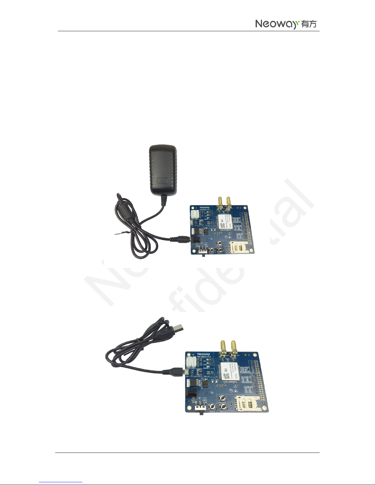
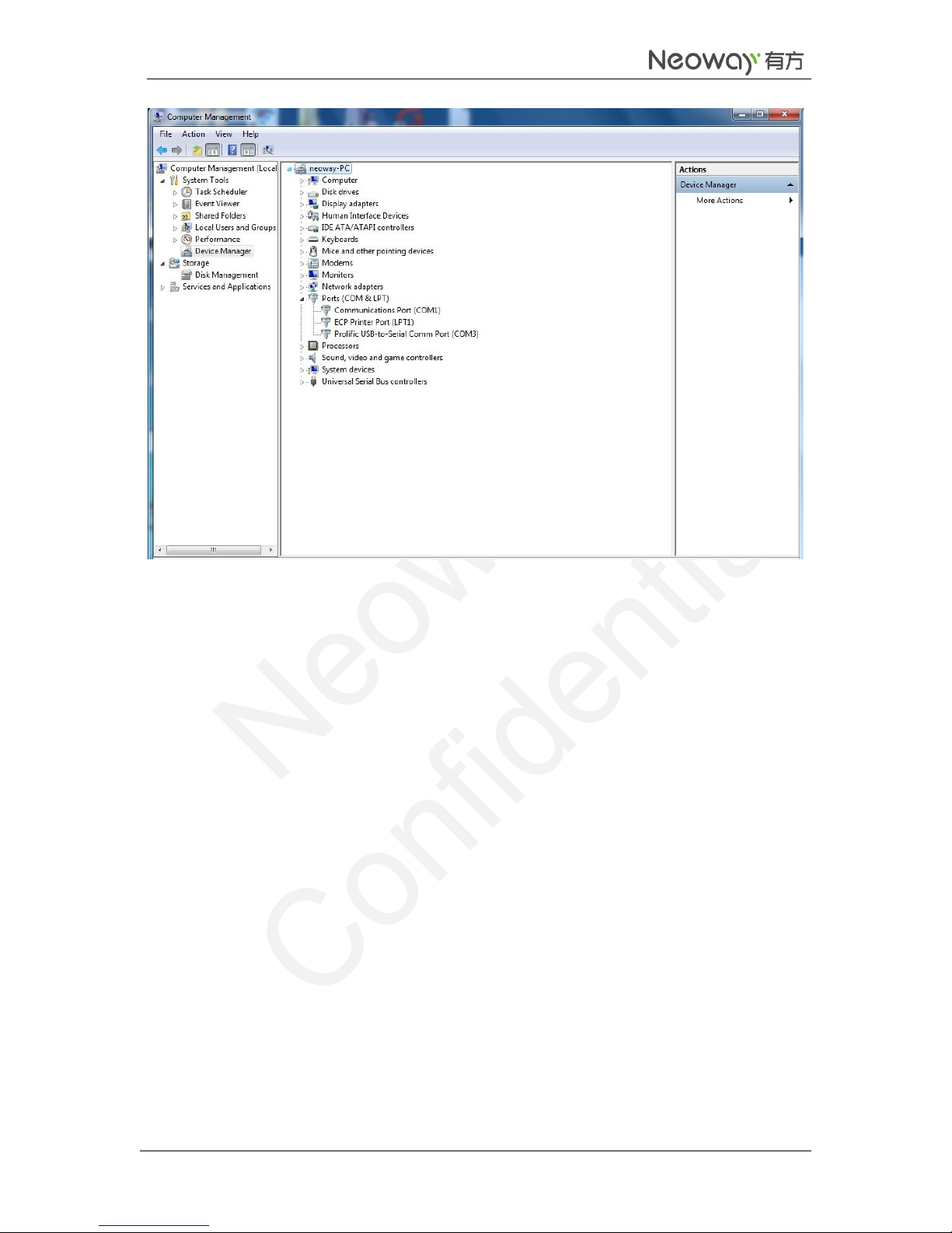
This document provides guide for users to use the N20 demo board.
This document is intended for system engineers (SEs), development engineers, and test engineers.
The information in this document is subject to change without notice due to product version update
or other reasons.
Every effort has been made in preparation of this document to ensure accuracy of the contents, but all
statements, information, and recommendations in this document do not constitute a warranty of any
kind, express or implied.
Neoway provides customers complete technical support. If you have any question, please contact
your account manager or email to
Website: http://www.neoway.com

N20 Demo Board User Guide
Copyright © Neoway Technology Co., Ltd
ii
Revision Record
Version
Changes
Revised By
Date
V1.0
Initial draft
Tian Yongshuang
2017-10

N20 Demo Board User Guide
Copyright © Neoway Technology Co., Ltd
1
Contents
1 Overview............................................................................................................................. 1
2 Board Interfaces ................................................................................................................. 1
3 Connections ........................................................................................................................ 2
3.1 Demo Board ....................................................................................................................................... 2
3.2 M5X0-PWR Board............................................................................................................................. 2
3.3 Power Supply ..................................................................................................................................... 3
3.3.1 5 V/2A Adapter.......................................................................................................................... 3
3.3.2 USB Cable................................................................................................................................. 3
3.4 Commissioning................................................................................................................................... 4
3.4.2 Commissioning Via UART........................................................................................................ 4
3.4.3 Commissioning Via USB .......................................................................................................... 6
4 Material List...................................................................................................................... 12

N20 Demo Board User Guide
Copyright © Neoway Technology Co., Ltd
1
1 Overview
N20 demo board is used for developers to evaluate the hardware and software functions. It provides
various peripheral interfaces, including power interface, USB, SIM card, antenna, PWRKEY, RESET, and
UART. Developers can commission the module though AT commands after connecting a power supply
and Micro USB.

N20 Demo Board User Guide
Copyright © Neoway Technology Co., Ltd
1
2 Board Interfaces
The following table lists the interfaces of N20 demo board.
Interface
Function
5 V power supply
Main power supply input, 3.3 V to 4.2 V
5 V power supply switch
Pull it to DC5V side to supply power if a DC adapter is used; pull it to
USB5V side to supply power if the board is supplied power through
USB.
SIM
Normal SIM card connector
UART0
Used to commission AT commands
UART1
Not supported
Antenna
Main antenna and GPS antenna
PWRKEY button
After supplying power to the module, hold this button for 1 second to
power up the module
RESET button
Hardware reset
USB
Used to supply power and transmit data & firmware upgrade
USB_BOOT
Force the module to enter download mode

N20 Demo Board User Guide
Copyright © Neoway Technology Co., Ltd
2
3 Connections
3.1 Demo Board
3.2 M5X0-PWR Board
GPS antenna
4G antenna
UART
USB
Power
supply
connector
Switch
PWRKEY
RESET
USB_BOOT
SIM connector

N20 Demo Board User Guide
Copyright © Neoway Technology Co., Ltd
3
3.3 Power Supply
N20 demo board supports two ways of power supply:
5V/2A DC power supply adapter
USB
3.3.1 5 V/2A Adapter
The demo board uses 5 V power supply. Plug the output end of the adapter to the DC connector on the
demo board. Pull the power supply switch to the DC5V side.
The following figure shows the recommended connection between 5 V/2A adapter and the demo board.
3.3.2 USB Cable
The following figure shows the Micro-USB cable used to connect the board to a computer for power
supply and data communication.

N20 Demo Board User Guide
Copyright © Neoway Technology Co., Ltd
4
3.4 Commissioning
The module can be commissioned through UART or USB.
Before commissioning, perform the following operations to get ready:
1. Connect antennas, including 4G antenna and GPS antenna.
2. Insert a SIM card.
3. Connect to the power supply and switch it on. Turn on the module.
The following sections describe the operations after the module is started.
3.4.2 Commissioning Via UART
Step 1 Insert the USB end of the M5X0-PWR cable to a computer.
The following figure shows how the board is connected to a computer via UART.
Step 2 Install the PL2303 USB-to-Serial driver.
Step 3 In Device Manager, check if Prolific USB-to-Serial Comm Port is displayed.

N20 Demo Board User Guide
Copyright © Neoway Technology Co., Ltd
5
Step 4 Start the UART commissioning tool.
Select the desired UART port and perform AT command commissioning.
For details about AT commands, see Neoway_N720_AT_Command_Mannual.

N20 Demo Board User Guide
Copyright © Neoway Technology Co., Ltd
6
3.4.3 Commissioning Via USB
Step 1 Connect the module to a computer though the USB and power on the module.
The following figure shows how the board is connected to a computer via USB.

N20 Demo Board User Guide
Copyright © Neoway Technology Co., Ltd
7
Step 2 Install the USB driver
1. Double-click the USB driver installation file Setup.
2. In InstallShield Wizard, click WWAN-DHCPis not used to get IPAddress and Next.
3. Click Next.

N20 Demo Board User Guide
Copyright © Neoway Technology Co., Ltd
8
4. Click I accept the terms in the license agreement and Next.
5. Click Install.

N20 Demo Board User Guide
Copyright © Neoway Technology Co., Ltd
9
Wait till the Status bar becomes green completely.
6. In the Windows Security dialog box, select Always trust software from "Qualcomm
Technologies,Inc.". and click Install.
Repeat this step for 5 times.
7. Click Finish.
The USB driver is installed completely.

N20 Demo Board User Guide
Copyright © Neoway Technology Co., Ltd
10
8. In Device Manager, check if the four ports are displayed.

N20 Demo Board User Guide
Copyright © Neoway Technology Co., Ltd
11
After the USB driver is installed, multiple serial ports are displayed. Modem 90B2 is the one used to
send AT commands.
Step 3 Start the UART commissioning tool.
Select the desired UART port and perform AT command commissioning.
For details about AT commands, see Neoway_N20_AT_Command_Mannual.

N20 Demo Board User Guide
Copyright © Neoway Technology Co., Ltd
12
4 Material List
N20 demo board (with/without module)
M5X0-PWR board
5 V power supply, 4G antenna, etc (Optional)
Other manuals for N20
2
Table of contents
Other Neoway Motherboard manuals