Neoway S720 User manual

EVB User Guide
Issue 1.0

S720 EVB User Guide
Copyright
Copyright © Neoway Technology Co., Ltd. All rights reserved.
ii
Copyright © Neoway Technology Co., Ltd. 2022. All rights reserved.
No part of this document may be reproduced or transmitted in anyform or by any means without prior written
consent of Neoway Technology Co., Ltd.
is the trademark of Neoway Technology Co., Ltd.
All other trademarks and trade names mentioned in this document are the property of their respective
holders.
Notice
This document provides a guide for users to use S720.
This document is intended for system engineers (SEs), development engineers, and test engineers.
THIS GUIDE PROVIDES INSTRUCTIONS FOR CUSTOMERS TO DESIGN THEIR APPLICATIONS.
PLEASE FOLLOW THE RULES AND PARAMETERS IN THIS GUIDE TO DESIGN AND COMMISSION.
NEOWAY WILL NOT TAKE ANY RESPONSIBILITY OF BODILY HURT OR ASSET LOSS CAUSED BY
IMPROPER OPERATIONS.
THE INFORMATION IN THIS DOCUMENT IS SUBJECT TO CHANGE WITHOUT NOTICE DUE TO
PRODUCT VERSION UPDATE OR OTHER REASONS.
EVERY EFFORT HAS BEEN MADE IN PREPARATION OF THIS DOCUMENT TO ENSURE ACCURACY
OF THE CONTENTS, BUT ALL STATEMENTS, INFORMATION, AND RECOMMENDATIONS IN THIS
DOCUMENT DO NOT CONSTITUTE A WARRANTY OF ANY KIND, EXPRESS OR IMPLIED.
Neoway provides customers complete technical support. If you have any question, please contact your
account manager or email to the following email addresses:
Sales@neoway.com
Support@neoway.com
Website: http://www.neoway.com

S720 EVB User Guide
Contents
Copyright © Neoway Technology Co., Ltd. All rights reserved.
iii
Contents
About This Document..................................................................................iv
Scope.................................................................................................................................................iv
Audience ............................................................................................................................................iv
Change History...................................................................................................................................iv
Conventions .......................................................................................................................................iv
Related Documents.............................................................................................................................v
1 S720 EVB Overview.................................................................................6
1.1 Accessories.................................................................................................................................. 6
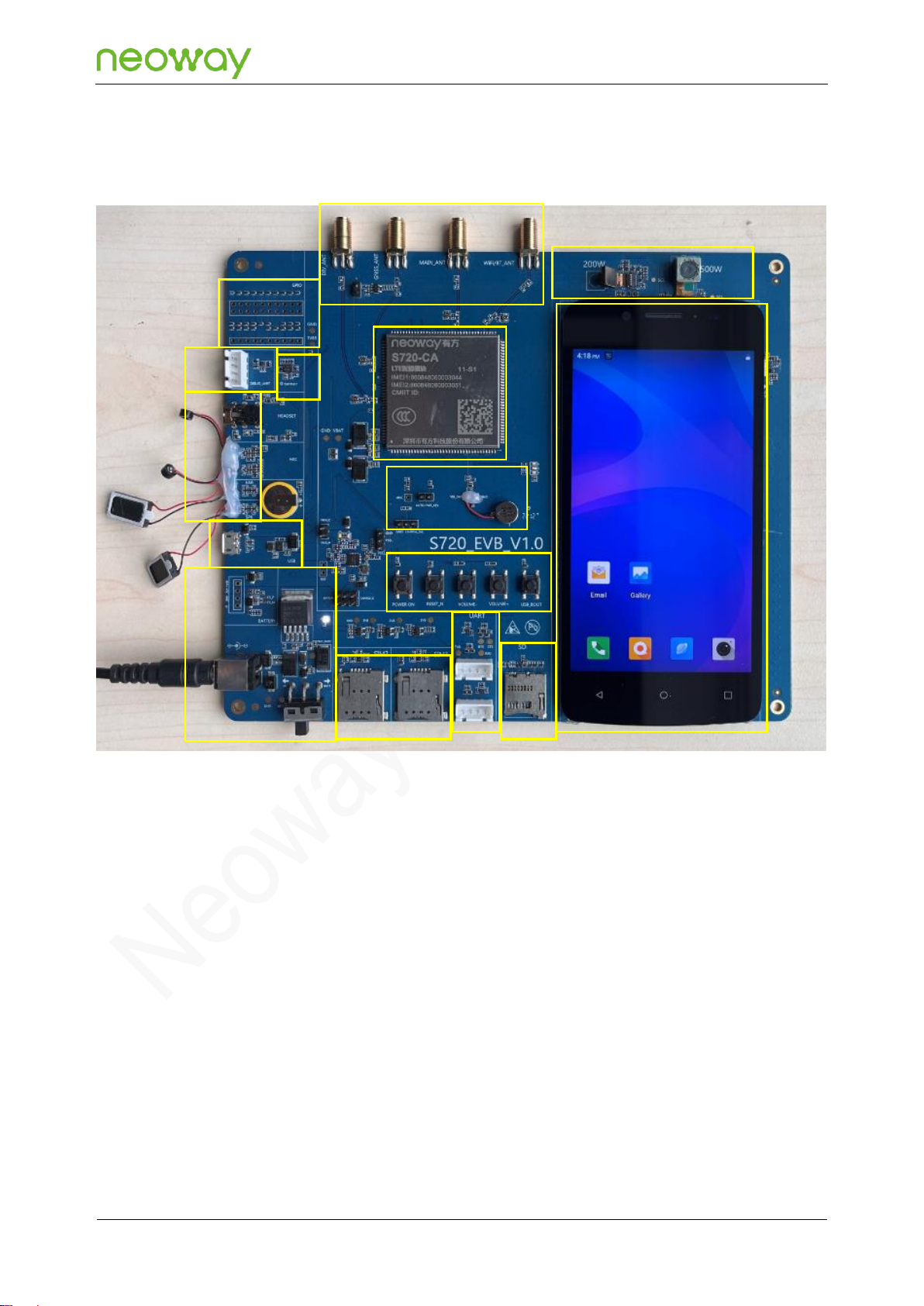
1.2 S720 EVB Introduction................................................................................................................. 7
2 Testing the S720 EVB ..............................................................................9
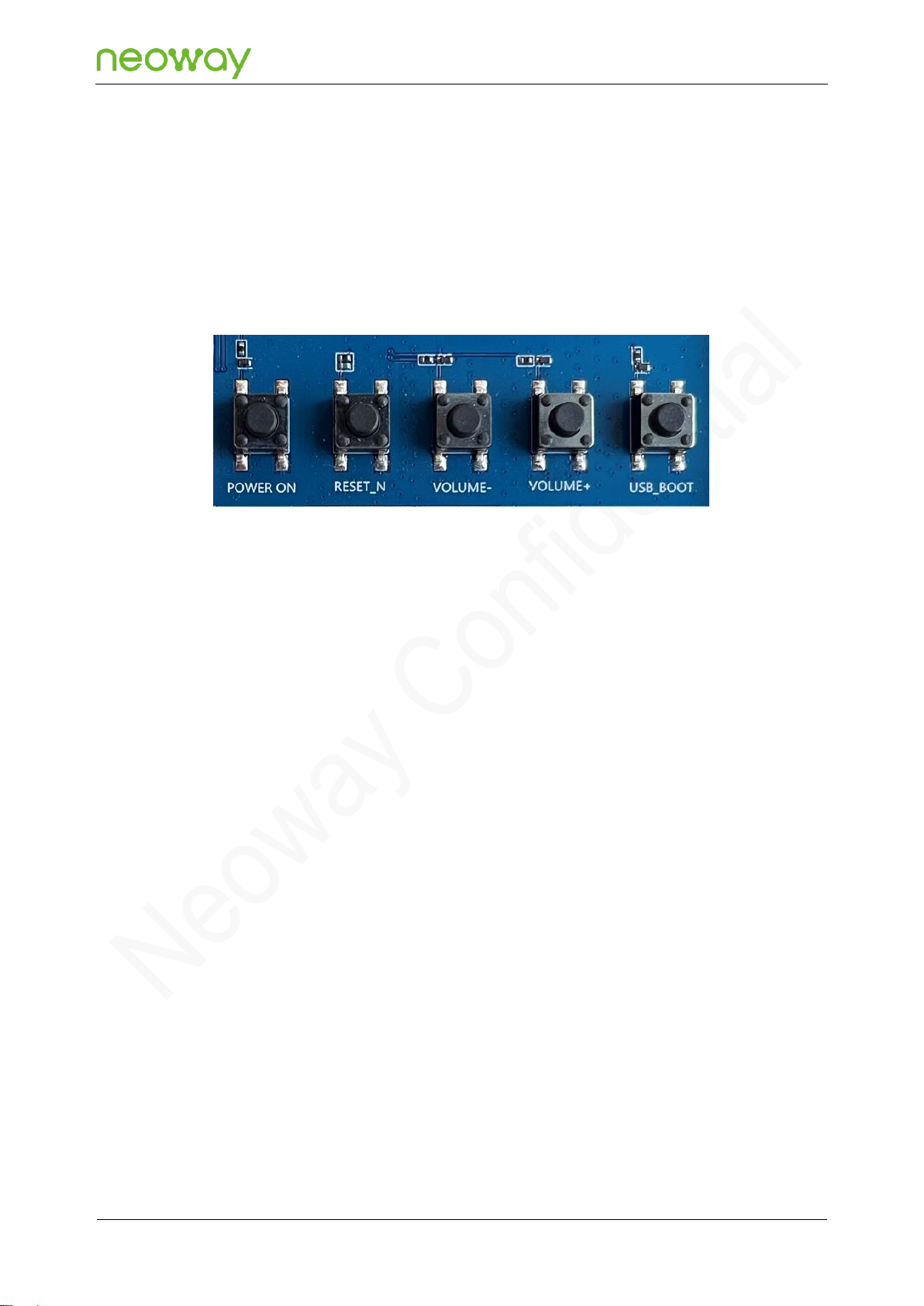
2.1 Button and Function Description.................................................................................................. 9
2.2 Power Supply and Power-on/Power-off Description.................................................................... 9
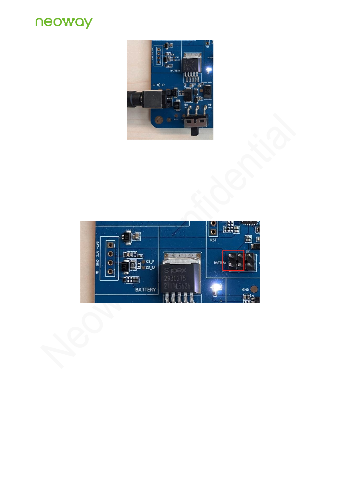
2.2.1 External DC Power Supply.................................................................................................. 9
2.2.2 Power Supply Using a Battery........................................................................................... 10
2.2.3 Power-on ............................................................................................................................11
2.2.4 Power-off ............................................................................................................................11
2.3 SIM Card Connectors................................................................................................................. 12
2.4 UART Interfaces......................................................................................................................... 12
2.5 SD Card Connector.................................................................................................................... 13
2.6 LCD and TP Interfaces............................................................................................................... 13
2.7 Camera Interfaces...................................................................................................................... 14
2.8 SMA Connector Interfaces......................................................................................................... 15
2.9 DEBUG_UART Interface............................................................................................................ 15
2.10 HEADSET, MIC, EAR, and SPK Interfaces ............................................................................. 16
2.11 USB Interface........................................................................................................................... 17
2.12 ADC and VIB_DRV Interfaces.................................................................................................. 18
2.13 Other Interfaces ....................................................................................................................... 18

S720 EVB User Guide
About This Document
Copyright © Neoway Technology Co., Ltd. All rights reserved.
iv
About This Document
Scope
This document is applicable to the S720 module. It provides a description of the relevant interfaces on
the EVB and how to use the S720 EVB.
Audience
This document is intended for system engineers (SEs), development engineers, and test engineers.
Change History
Issue
Change
Author
1.0
Initial issue.
Luo Jian
Conventions
Symbol
Description
Indicates danger or warning. This information must be followed. Otherwise, a
catastrophic module or user device failure or bodily injury may occur.
Indicates caution. This symbol alerts the user to important points about using the
module. If these points are not followed, the module or user device may fail.
Indicates instructions or tips. This symbol provides advices or suggestions that
may be useful when using the module.

S720 EVB User Guide
About This Document
Copyright © Neoway Technology Co., Ltd. All rights reserved.
v
Related Documents
Neoway_S720_Product_Specifications
Neoway_S720_Hardware_User_Guide

S720 EVB User Guide
Chapter 1 S720 EVB Overview
Copyright © Neoway Technology Co., Ltd. All rights reserved.
6
1 S720 EVB Overview
S720 provides a variety of peripheral interfaces, including power, USB, commissioning UART, GPIO,
and UART interfaces. Customers can connect the corresponding external devices to the S720 EVB for
commssioning according to their own needs.
1.1 Accessories
S720 EVB
Power adapter
LCD and TP
Primary/Secondary camera
USB-to-UART cable
USB data cable
Antenna

S720 EVB User Guide
Chapter 1 S720 EVB Overview
Copyright © Neoway Technology Co., Ltd. All rights reserved.
7
1.2 S720 EVB Introduction
Figure 1-1 S720 EVB front view
1
2
4
7
8
14
6
9
10
12
13
15
3
5
11

S720 EVB User Guide
Chapter 1 S720 EVB Overview
Copyright © Neoway Technology Co., Ltd. All rights reserved.
8
Table 1-1 Interface description
No.
Description
No.
Description
1
S720 module
9
Other module IO interfaces
2
DC power input, power switch, and
battery interfaces
10
DEBUG_UART interface
3
SIM1 and SIM2 card connectors
11
G-sensor
4
UART interface
12
HEADSET, MIC, EAR, and SPK
interfaces
5
SD card connector
13
USB interface
6
LCD and TP
14
ADC and VIB_DRV interfaces
7
Rear/front camera
15
POWER ON, RESET_N, VOLUME-,
VOLUME+, USB_BOOT buttons
8
Secondary SMA connector, GPS SMA
connector, primary SMA connector,
and Wi-Fi/BT SMA connector

S720 EVB User Guide
Chapter 2 Testing the S720 EVB
Copyright © Neoway Technology Co., Ltd. All rights reserved.
9
2 Testing the S720 EVB
2.1 Button and Function Description
POWER ON: module power-on/power-off button
RESET_N: module reset button
VOLUME-: volume down button
VOLUME+: volume up button
USB_BOOT: used for firmware download
Before powering on the S720 EVB, press and hold the USB_BOOT button and then power on the
module (the module startup is not required) to enter the download mode.
2.2 Power Supply and Power-on/Power-off Description
The S720 EVB has two power supply methods: external DC power supply and power supply using a
battery. Different power supply methods have different positions of the power supply switch.
2.2.1 External DC Power Supply
Step 1: Insert the matching 5 V power adapter into the DC power input interface.
Step 2: Turn the power supply switch to the "DC5V" position, as shown in the following figure.
After the DC power supply properly supplies power to the S720 EVB, the power indicator shown
in the following figure is on.

S720 EVB User Guide
Chapter 2 Testing the S720 EVB
Copyright © Neoway Technology Co., Ltd. All rights reserved.
10
2.2.2 Power Supply Using a Battery
It is recommended to use a 3.5 V to 4.2 V lithium battery for power supply. The battery interface is
shown as BATTERY in the following figure.
The S720 EVB reserves the battery 4-pin interfaces: BAT+, NTC, GND, and ID interfaces.
Step 1: Connect the battery to the 4-pin battery interfaces reserved by the EVB.
Using a battery to supply power requires the two pins on the left of the jumper cap.

S720 EVB User Guide
Chapter 2 Testing the S720 EVB
Copyright © Neoway Technology Co., Ltd. All rights reserved.
11
Step 2: Turn the power supply switch to the "BATT" position.
After the battery properly supplies power to the S720 EVB, the power indicator is on.
2.2.3 Power-on
The POWER ON button is the power-on/power-off button.After the S720 EVB is powered on, you can
press and hold the POWER ON button for about 3 seconds to start the module.
2.2.4 Power-off
If the S720 EVB is in the running state, press and hold the POWER ON button for about 3 seconds.A
pop-up prompt box is displayed on the main interface. Select the "Power off" option to power off the
module.

S720 EVB User Guide
Chapter 2 Testing the S720 EVB
Copyright © Neoway Technology Co., Ltd. All rights reserved.
12
2.3 SIM Card Connectors
SIM1 card connector, supporting 4G TDD-LTE, FDD-LTE, WCDMA, and GSM networks
SIM2 card connector, supporting 4G TDD-LTE, FDD-LTE, WCDMA, and GSM networks
2.4 UART Interfaces
Two UART interfaces, which can be connected to a UART interface device for commissioning.

S720 EVB User Guide
Chapter 2 Testing the S720 EVB
Copyright © Neoway Technology Co., Ltd. All rights reserved.
13
2.5 SD Card Connector
SD card connector on the S720 EVB. You can use an SD card to test an SD card connector.
2.6 LCD and TP Interfaces
LCD and TP interfaces can be used only after they are connected to the LCD and TP that match the
S720 EVB. LCD and TP interfaces cannot be used if they are connected to other models of display
and touch screens.

S720 EVB User Guide
Chapter 2 Testing the S720 EVB
Copyright © Neoway Technology Co., Ltd. All rights reserved.
14
2.7 Camera Interfaces
Camera interfaces can be used onlyif they are connected to matching cameras of the S720 EVB.They
cannot be used if they are connected to other models of cameras.

S720 EVB User Guide
Chapter 2 Testing the S720 EVB
Copyright © Neoway Technology Co., Ltd. All rights reserved.
15
Front camera, connected to a 200W pixel camera.
Rear camera, connected to a 500W pixel camera.
2.8 SMA Connector Interfaces
Wi-Fi/BT_ANT, supporting 2.4 GHz Wi-Fi. Wi-Fi/BT_ANT can be used after being connected to a
2.4 GHz antenna.
MAIN_ANT, which is a primary antenna interface. MAIN_ANT can be used after being connected
to a 4G full-band antenna.
GPS_ANT, which is a GPS antenna interface. GPS_ANT can be used after being connected to a
GPS passive antenna. If an active antenna needs to be used, use a jumper cap to connect the
pins next to it.
DIV_ANT, which is a secondary antenna interface. DIV_ANT can be used after being connected
to a 4G full-band antenna.
The antenna on the module is connected to the IPEX connector by default. If an SMA connector needs to be
used, connect the resistor on the antenna path to the SMA connector.
2.9 DEBUG_UART Interface
The DEBUG_UART interface is the default log printing interface. During commissioning, you can
connect the UART cable to print logs for commissioning.

S720 EVB User Guide
Chapter 2 Testing the S720 EVB
Copyright © Neoway Technology Co., Ltd. All rights reserved.
16
2.10 HEADSET, MIC, EAR, and SPK Interfaces
HEADSET interface, which can be connected to a headset for testing.
MIC interfaces. Two MICs on the EVB are separately connected to electret MICs.
SPK interface. The speaker interface output uses differential output and built-in class D power
amplifier. The maximum output power is 0.8 W when the load is 8 Ω.
EAR interface, which can be connected to an earpiece for testing.

S720 EVB User Guide
Chapter 2 Testing the S720 EVB
Copyright © Neoway Technology Co., Ltd. All rights reserved.
17
2.11 USB Interface
USB interface, which can be connected to a computer by using a USB cable for commissioning and
file transfer.

S720 EVB User Guide
Chapter 2 Testing the S720 EVB
Copyright © Neoway Technology Co., Ltd. All rights reserved.
18
2.12 ADC and VIB_DRV Interfaces
ADC interface, which can be used forADC testing.
VIB_DRV interface, which can be connected to a motor for testing.
2.13 Other Interfaces
The S720 EVB provides GPIO, I2C, UART, and other interfaces, as shown in the following figure. For
details about the pin description, see Neoway_S720_Hardware_User_Guide.
Other manuals for S720
2
Table of contents
Other Neoway Motherboard manuals