N10 Demo Board User Guide
Copyright © Neoway Technology Co., Ltd 4
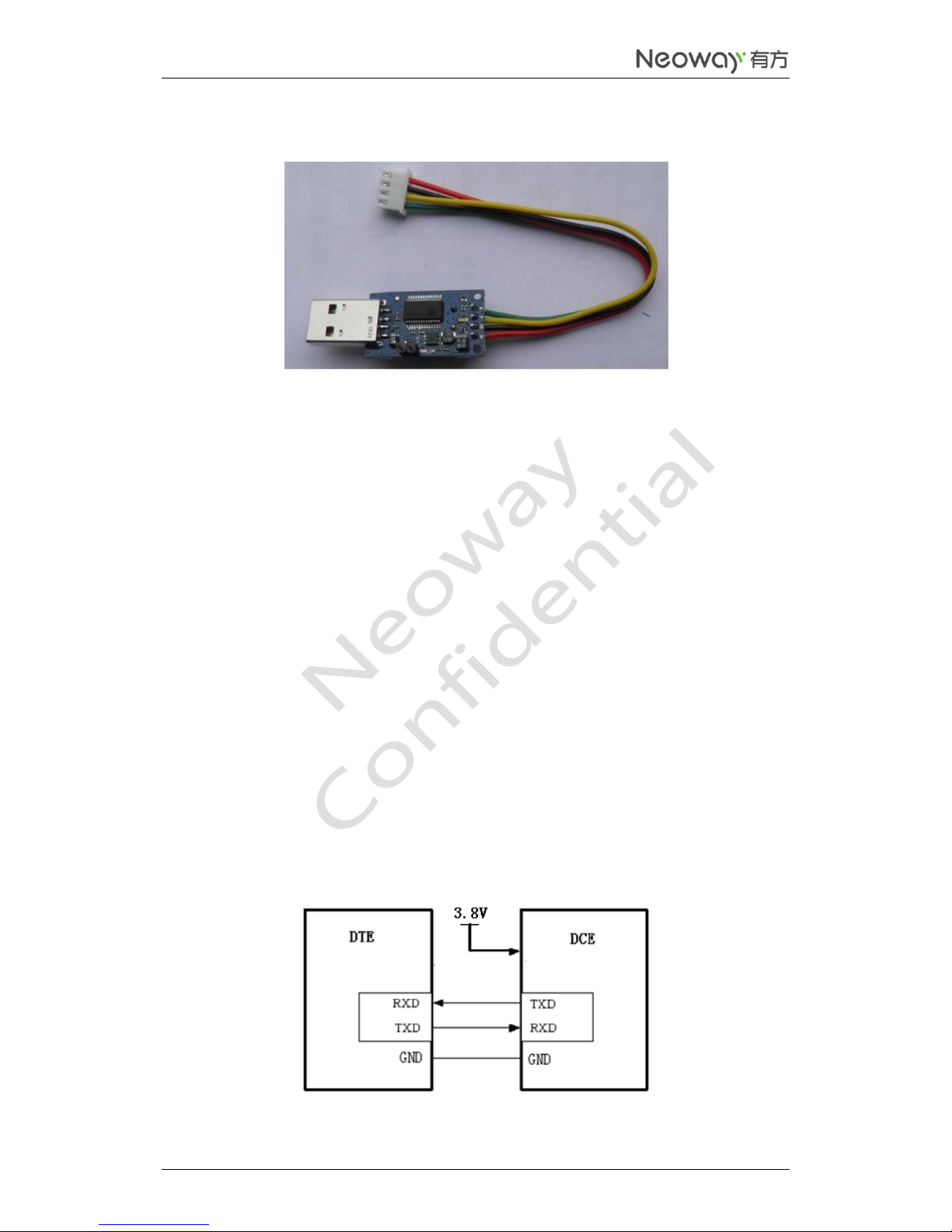
3.2.2 M5X0-PWR serial port board
The above picture is the M5X0-PWR serial port board, the main function is supply power to the module
via computer USB interface with the voltage of 3.8V / 0.6A, and through the USB to serial chip output
3.3V COMS logic level, TXD / RXD achieve computer and module to communicate. The connection with
the development board is through the supply of power and serial port cable connect line as red, black,
yellow, green order from bottom to top soldering to the power board, the other side plugged into the
development board socket. PWR board has two pins, through disconnect or short-circuit them to open or
close the supply power to the module.
M5X0-PWR board and the development board serial port connected to the 4pin socket as following:
Green: module send data (TXD), output, 2.85V CMOS logic level;
Yellow: module receive data (RXD), input, CMOS logic level, the maximum voltage it can withstand
is 3.3V
Black: main ground;
Red: VBAT, the main power input, 3.6 ~ 4.5V, recommended 3.8V.
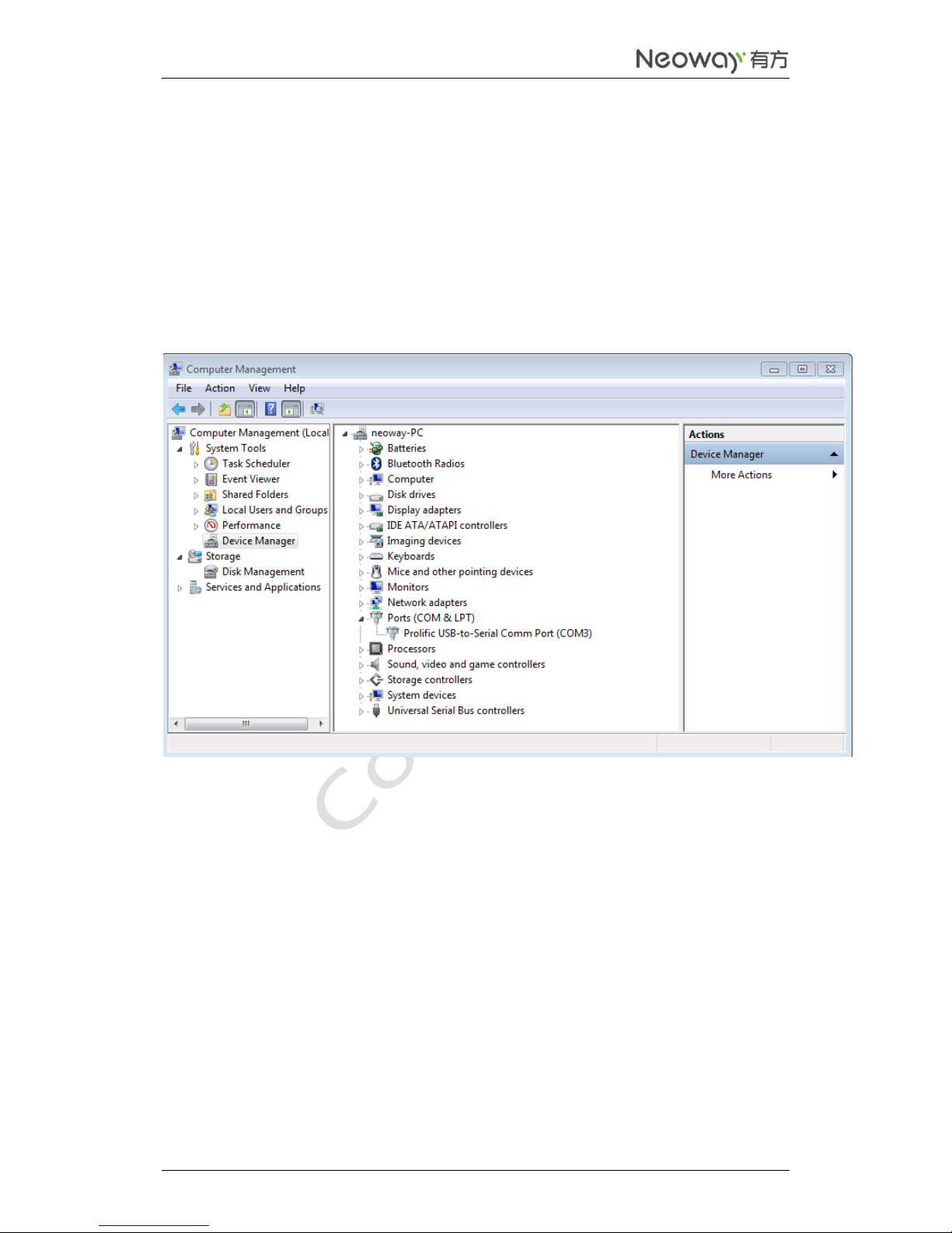
If you use the serial port function, you need to install the USB driver (PL2303); when using the MCU to
control the development of the module, you need to connect the above 4 lines, the connections are as
shown below: