Neslab Steelhead 1 Manual

-~
ARTISAN
®
~I
TECHNOLOGY
GROUP
Your definitive source
for
quality
pre-owned
equipment.
Artisan Technology
Group
Full-service,
independent
repair
center
with
experienced
engineers
and
technicians
on staff.
We
buy
your
excess,
underutilized,
and
idle
equipment
along
with
credit
for
buybacks
and
trade-ins
.
Custom
engineering
so
your
equipment
works
exactly as
you
specify.
•
Critical
and
expedited
services
•
Leasing
/
Rentals/
Demos
• In
stock/
Ready-to-ship
•
!TAR-certified
secure
asset
solutions
Expert
team
ITrust
guarantee
I
100%
satisfaction
All
tr
ademarks,
br
a
nd
names, a
nd
br
a
nd
s a
pp
earing here
in
are
th
e property of
th
e
ir
r
es
pecti
ve
ow
ner
s.
Find the Thermo / Neslab Steelhead 3 CHX at our website: Click HERE

Instruction and Operation Manual
Thermo Manual P/N U00206
Rev. 06/11/04
STEELHEAD 1 CE97
30°C to 130°C
Stainless Steel
Heat Exchanger
w/ M DIC MM RS-485 (CHX)
Serial Communication
Model 620099991707
Artisan Technology Group - Quality Instrumentation ... Guaranteed | (888) 88-SOURCE | www.artisantg.com

STEELHEAD HEAT EXCHANGER
PREFACE
Compliance ........................................................................................................ 2
Nameplate Data ................................................................................................. 2
Unpacking ........................................................................................................... 2
After-sale Support ............................................................................................... 2
SECTION I SAFETY
Warnings ............................................................................................................. 3
Material Safety Data Sheets ............................................................................... 3
SECTION II GENERAL INFORMATION
Description..........................................................................................................
Specifications .....................................................................................................
SECTION III INSTALLATION
Site ...................................................................................................................... 5
Electrical Requirements ..................................................................................... 5
Safety Control Requirements ............................................................................. 5
Plumbing Requirements .................................................................................... 6
Facility Water Requirements .............................................................................. 6
Fluids .................................................................................................................. 6
Front Panel Gauges ........................................................................................... 7
Front Panel Controls ........................................................................................... 7
Low Profile Membrane Key Functions ................................................................ 9
LED Indicators .................................................................................................... 10
Controller Loops ................................................................................................. 12
Error Messages .................................................................................................. 15
MODICOMM RS- 85 (CHX) ................................................................................ 16
Serial Communication Specifications ................................................................ 16
SECTION IV OPERATION
Pre Start Up & Filling Requirements .................................................................. 18
Start Up & Shut Down ......................................................................................... 19
Changing a Value ............................................................................................... 20
Remote Operation .............................................................................................. 20
Temperature Control .......................................................................................... 21
Flow Control ........................................................................................................ 21
Flow Monitors ...................................................................................................... 21
Low Level Monitors ............................................................................................. 21
Resistivity and Temperature Sensor .................................................................. 21
SECTION V PREVENTATIVE MAINTENANCE
Service Contracts ................................................................................................ 22
General Guidelines ............................................................................................ 22
Daily Preventative Maintenance .......................................................................... 2
Fluid Inspection/Draining ................................................................................... 25
Fluid pH ............................................................................................................... 25
Stainless Steel Particulate Filter ........................................................................ 26
Barnstead DI Filter .............................................................................................. 26
Culligan DI Filter ................................................................................................. 27
Pump Motor Ball Bearing Lubrication ................................................................ 27
Reservoir Cleaning ............................................................................................. 27
SECTION VI TROUBLESHOOTING
Facililitization Problem Troubleshooting ............................................................ 28
Error Message Troubleshooting ........................................................................ 30
SECTION VII DIAGRAMS
Flow Diagram ..................................................................................................... 33
Fork Lift Channel Dimensions ........................................................................... 3
Wiring Diagram ................................................................................................... 35
APPENDIX A
Remote Electronic Interface ............................................................................... A-1
APPENDIX B
Quick Start Up Procedures ................................................................................. B-1
APPENDIX C
Using the AMAT Heat Exchanger Configuration Touch Screen ......................... C-1
Artisan Technology Group - Quality Instrumentation ... Guaranteed | (888) 88-SOURCE | www.artisantg.com

- 2 -
Preface
Com liance
This product has been tested and found to be in compliance with the require-
ments defined in the EMC standards defined by 89/33 /EEC as well as Low
Voltage Directive (LVD) 73/23/EEC and the Machinery Directive 93/44/EEC .
The testing has demonstrated compliance with the following directives:
LVD, 73/23/EEC Complies with UL 3101-1:93 and IEC 1010-1
EMC, 89/33 /EEC EN 55011, Class A Verification
IEC 1000-4-2:1995 Electro-Static Discharge
IEC 1000-4-3:1994 Radiated Elecromagnetic Field
IEC 1000-4-4:1995 Conducted Electrical Fast Transient/Burst
93/44/EEC Machinery Directive
For any additional information refer to the Letter of Compliance that shipped
with the unit (Declaration of Conformity).
Name late Data
MODEL: STEELHEAD 1 PHASE: 3/PE 4WIRE
FREQUENCY: 50/60 HERTZ
FULL LOAD AMPS: 23/25
HEATER: 6KW 208VOLTS PUMP: 3.0 HP
LARGEST LOAD HEATER 16.7 AMPS
INTERRUPT CAPACITY: 10KA PER EN60898
10KAIC W/MAX 120 AMP FUSE PER UL1077
MASS: 385LBS 174KG
ELECTRICAL DIAGRAM: 6.3259
Un acking
Retain all cartons and packing material until the unit is operated and found to
be in good condition. If the unit shows external or internal damage contact the
transportation company and file a damage claim. Under ICC regulations, this is
your responsibility.
After-sale Su ort
Thermo Electron Corporation is committed to customer service both during and
after the sale. If you have questions concerning the operation of your unit,
contact our Sales Department. Before calling, please refer to the serial number
label on the rear of the unit to obtain the following information (see Section II,
Description for serial number label location):
- unit BOM number__________________________________
- unit serial number _________________________________
Artisan Technology Group - Quality Instrumentation ... Guaranteed | (888) 88-SOURCE | www.artisantg.com

- 3 -
Section I Safety
Warnings
Make sure you read and understand all instructions and safety precautions
listed in this manual before installing or operating your unit. If you have any
questions concerning the operation of your unit or the information in this
manual, please contact our Sales Department (see After-sale Support).
Performance of installation, operation, or maintenance procedures
other than those described in this manual may result in a hazardous
situation and may void the manufacturer's warranty.
Transport the unit with care. Sudden jolts or drops can cause damage.
Do not attempt to move the unit without proper lifting or moving e uip-
ment serious injury can occur.
Do not lift unit by the filter.
Observe all warning labels.
Never remove warning labels.
Never operate damaged or leaking e uipment.
Never operate the unit without fluid in the reservoir.
Always lock the main circuit breaker in the OFF position, turn off the
unit and disconnect the power supply from the power source before
performing any service or maintenance, or before moving the unit.
Never operate e uipment with damaged power cords.
Refer service and repairs to a ualified technician.
Some circuits in the enclosure will remain energized even with the line
cord disconnected. Control voltages will be present. If repairs are
authorized inside the enclosure, the main power and 15-pin plug must
be removed from the unit.
In addition to the safety warnings listed above, warnings are posted
throughout the manual. Read and follow these important instructions. Failure
to observe these instructions can result in permanent damage to the unit,
significant property damage, or personal injury or death.
Material Safety
Data Sheets
Ethylene Glycol Union Carbide Chemicals and Plastics Company Inc.
Industrial Chemicals Division
39 Old Rid ebury Road
Danbury, CT 06819-000
307-744-3487
Teflon® Paste Hercules Chemical Company
Passaic, NJ 07055-7398
1-800-221-9330
De-Ox Anti-Oxident Ilsco
4730 Madison Road
Cincinnati, OH 45227
513-871-4000
If you have Internet access, you can access numerous MSDS forms via the EPA
Chemical Substances Database.
Cornell Univ. has ~325,000 on line searchable MSDS at
http://www.pdc.cornell.edu/issearch/msdssrch.htm
Artisan Technology Group - Quality Instrumentation ... Guaranteed | (888) 88-SOURCE | www.artisantg.com

- 4 -
S ecifications
Temperature Range
Reservoir Volume
Unit Dimensions
(Outer Envelope)
(H x W x D)
Frame Dimensions
(H x W X D)
Cooling Capacity1
Heating Capacity2
Flow 3
Pressure
5 Gallons
19 Liters
8KW @ 5.0 GPM Facility Water Flow Rate
KW @ 208V
8.0 Gallons/Minute
30.3 Liters/Minute
30 to 0 PSI - 130 PSI Max
1. 22°C facility water with 2 - 8 GPM process water flow rate. 8°C or greater difference
between process water and facility water.
2. 39 watts per s uare inch.
3. 15 meters from unit through 3/8 inch ID hose. Flow split e ually between flow channels.
30°C to 130°C
Section II General Information
Descri tion
The heat exchanger system consists of a thermal fluid recirculating system
which provides a constant fluid flow. A second loop consists of a facilities
water loop which recirculates through a plate heat exchanger for fluid cooling.
A kilowatt heater is located in the fluid recirculating system.
The recirculating fluid loop has a deionizing package with a replaceable
cartridge and a 20 micron particulate filter with a replaceable filter element. A
small plate heat exchanger is used to cool the fluid entering the deionizing
cartridge.
Throughout the manual, you will be asked to consult the units serial number label for
specific information. The label is located on the right of the control box.
32 x 203/8 x 313/8 Inches
812.8 x 517.5 x 79 .9 Millimeters
28½ x 20 x 25 Inches
723.9x 508.0 x 35.0 Millimeters
Artisan Technology Group - Quality Instrumentation ... Guaranteed | (888) 88-SOURCE | www.artisantg.com

- 5 -
Section III Installation
Site
Locate the unit in a laboratory or clean industrial environment where ambient
temperatures are inside the range of +10°C to +40°C (+50°F to +104°F).
Never place the unit in a location where excessive heat, moisture, or
corrosive materials are present.
Excessively dusty areas should be avoided and a periodic cleaning schedule
should be instituted.
Install the Steelhead unit on a level surface. The unit is equipped with locking
casters on the front left and right rear of the unit to prevent movement. The
unit is also equipped with adjustable leveling feet.
To prevent damage, raise the leveling feet to the full up position when
not in use. Secure the leveling feet by securing the jam nut on the
leveling foot shaft to the case bottom.
The unit is designed to stand alone or can also be stacked with another
Steelhead unit, or a standard AMAT 0 or 1 heat exchanger. See the Fork Lift
Channel Dimension Diagram in Section VII.
Electrical
Requirements
The unit construction provides protection against the risk of electrical
shock by grounding appropriate metal parts. It is the user's responsibil-
ity to assure that a proper ground connection is provided to the unit.
Rated Voltage: 200 to 208VAC, 50/ 0Hz, 3Ø
Rated Circuit: 30Amps
Make sure the voltage of the power source meets the specified voltage, ±10%.
Safety Control
Requirements
EMERGENCY OFF guarded mushroom push-button with pull reset is pro-
vided to turn off the unit in case of an emergency. An EMERGENCY OFF
connector is provided on the top left portion of the rear of the unit to include
the system into the emergency off circuit. An isolated set of normally closed
contacts is provided for the EMERGENCY OFF safety circuit. Contact rating
is 0AMP make and 10AMP break at 24VAC.
The EMERGENCY OFF safety connector receptacle port is part number AMP
20 0 1-1. The mating plug part number is AMP 20 0 0-1 which uses sock-
ets part number AMP 101-1.
Artisan Technology Group - Quality Instrumentation ... Guaranteed | (888) 88-SOURCE | www.artisantg.com
- -
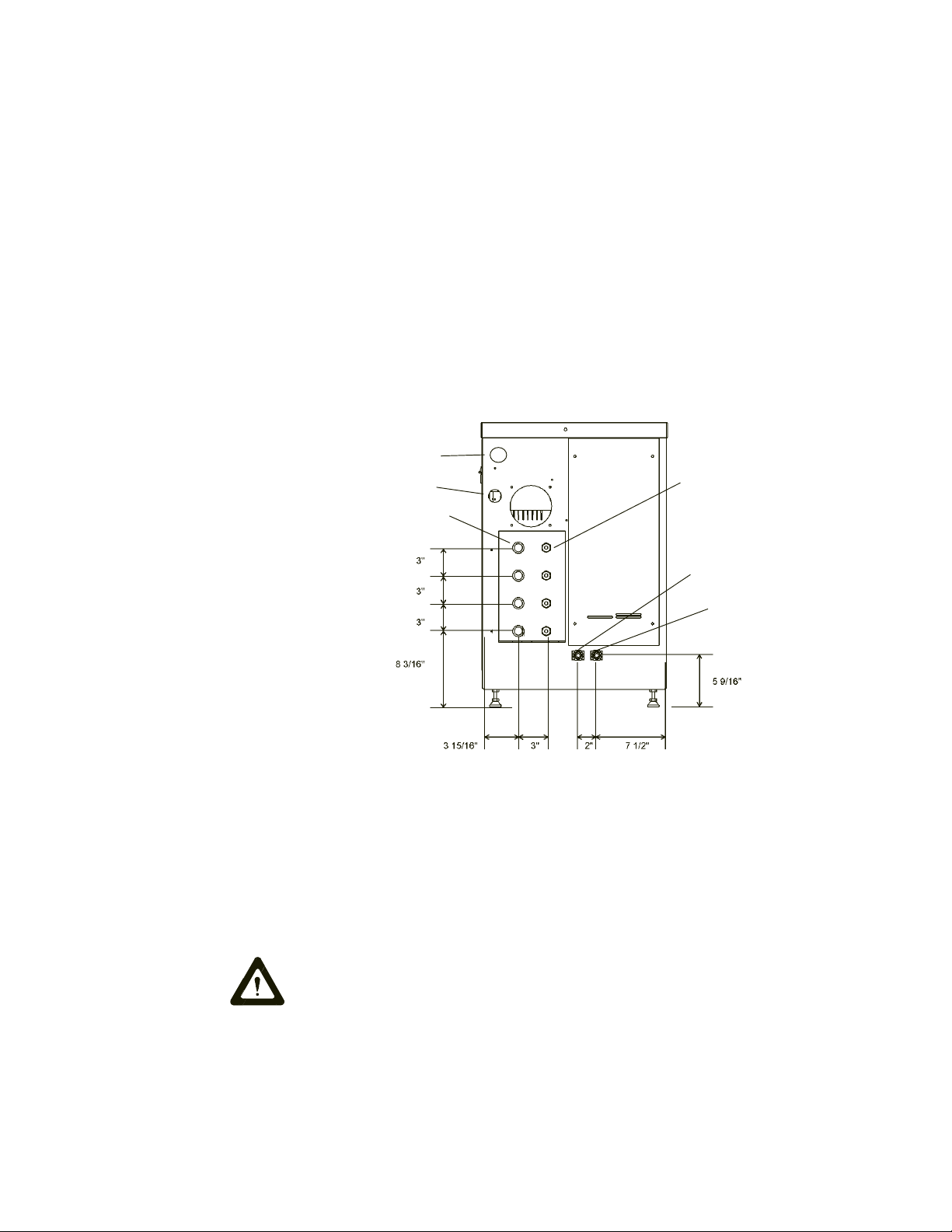
Plumbing
Requirements
The plumbing connections are located on the bottom rear of the unit and are
labelled THERMAL FLUID CHAMBER #1, #2, #3, #4. The four THERMAL
FLUID SUPPLY (to the tool) connections have ½" quick disconnect nipples.
The four THERMAL FLUID RETURN (from the tool) connections have ½"
quick disconnect couplers.
Keep the distance between the heat exchanger system and your application
as short as possible, and use the largest diameter tubing practical. Tubing
should be straight and without bends. If diameter reductions are needed make
them at the inlet and outlet of your application, not at the heat exchanger
system.
Facility Water Requirements
Facility water inlet and outlet connections are located at the bottom-center-
rear of the unit and are labelled FACILITY WATER. The facility water connec-
tions are 3/8" (Parker push-loc male hose nipples).
Fluids
Never use flammable or corrosive fluids with this unit. Do not use
automobile anti-freeze. Commercial anti-freeze contains silicates that
can damage the pump seals and cause leaks. Use of automobile anti-
freeze will void the manufacturers warranty.
The unit is designed to use a 100% electronic grade ethylene glycol as
the thermal fluid. Change the fluid as required, see Section V.
Facility Water Inlet
Thermal Fluid Return
(from the tool)
Power Inlet
EMO Connector J3
Facility Water Outlet
Thermal Fluid Supply
(to the tool)
Artisan Technology Group - Quality Instrumentation ... Guaranteed | (888) 88-SOURCE | www.artisantg.com
- 7 -
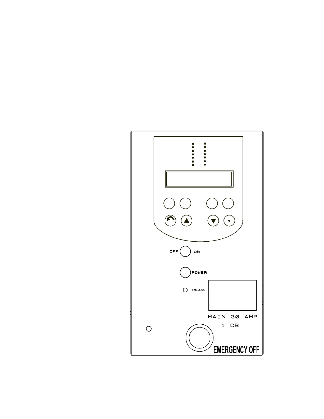
Front Panel
Gauges
1. Pump Pressure. Reads the pressure at the outlet of the unit.
2. Filter Pressure Gauge. The filter cartridge should be cleaned/replaced
when the gauge reads 1Bar (15psi) more than the pump pressure gauge.
Front Panel
Controls
Main Disconnect Circuit Breaker
30 Amp, 3 Pole 10 KAIC used to locally disconnect main power at the unit.
HEAT ENABLE
COOL
PUMP
LOCAL
REMOTE
FLUID LEAK
LEVEL FAULT
EXT SENSOR
LOW FLOW
ADD FLUID
FILTER
BREAKERS
HIGH TEMP
HEAT
ON/OFF LOC/REM INT/EXT RESET
NEXT YES NO ENTER
RS485
HIGH TEMP
RESET
Artisan Technology Group - Quality Instrumentation ... Guaranteed | (888) 88-SOURCE | www.artisantg.com

- 8 -
Pad Lock - Lockout
When the unit is not in use or is being serviced, the Pad Lock - Lockout
should be used. The lockout requires a padlock with a ¬ diameter shackle.
POWER - Amber
The POWER light indicates that the main disconnect circuit breaker is on,
power is available, and the control and secondary circuit breakers (in the
electrical enclosure) are on.
RS485
The RS485 light indicates that the serial communication mode (MODICOMM/
RS485) is active. The light flashes each time a query is received.
ON/OFF
Turning the ON/OFF rotary switch to the ON position enables the unit. The
controller illuminates and runs a diagnostic test, and then the unit enters the
standby mode.
Turning the ON/OFF rotary switch to the OFF position disables the unit.
NOTE: The machine circuit is interlocked to the electrical enclosure so the
removal of the panel will turn off the unit and the controller.
HEATER HIGH TEMPERATURE MANUAL RESET
The HEATER HIGH TEMPERATURE MANUAL RESET button allows the
heater high temperature switch to be reset once the temperature is below the
Heater High Temperature setting.
Resetting the button will automatically start the unit if the unit is in the
ON mode.
J1
DB-15 Female Connector. J1 connects to the standard AMAT 5000 Heat
Exchanger Interface. See Appendix A for connector and pinout information.
Supplying the wrong voltage to any of the remote interface pins can
seriously damage the controller. Verify that the cable is plugged into the
correct port on the AMAT tool before beginning remote operation.
J2
DB-9 Female Connector. J2 connects to an approved AMAT temperature
probe for external temperature control, display and temperature feedback
signal.
J4 & J5
DB-9 Female Connectors. Configured for RS485 and MODICOMM Serial
Communication Protocol.
Artisan Technology Group - Quality Instrumentation ... Guaranteed | (888) 88-SOURCE | www.artisantg.com
- 9 -
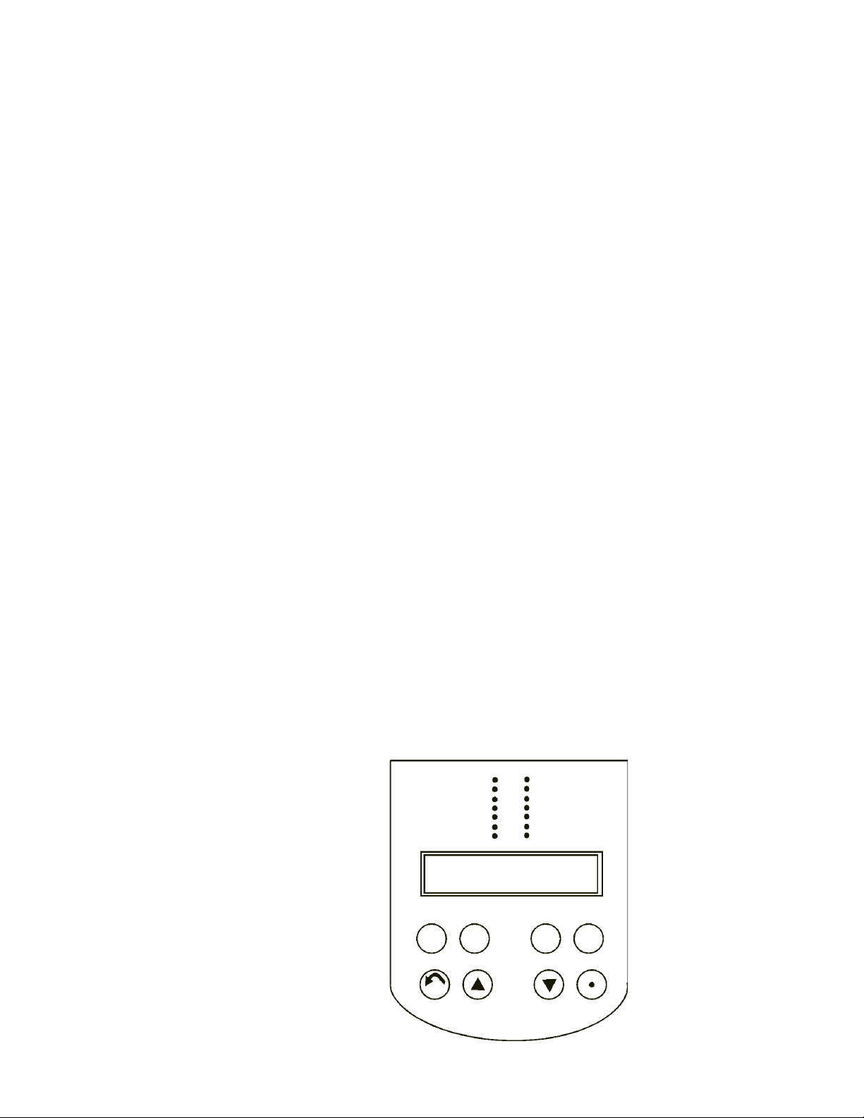
Low Profile Membrane
Key Functions
ON/OFF
The ON/OFF key toggles the controller from on to off and vice versa. The
controller will not switch to the ON mode unless proper conditions exist inside
the unit. See Error Messages in this section.
LOC/REM RS485
The LOC/REM RS485 key toggles the unit from local to remote to RS485
operation. The RS485 mode is serial communication.
INT/EXT
The INT/EXT key switches between the internal and external RTD probe.
Display #1 will alternate from INT T XXC to EXT T XXC. The control of the
fluid temp will switch from internal RTD probe to the external RTD probe. If
there is no external probe the controller will continue to display and to control
from the internal RTD probe.
RESET
The RESET key will attempt to clear the Add Fluid or Change Filter condition
status.
NEXT
The NEXT key is used to sequence through the controller displays.
YES
The YES key is used to increment values displayed on the controller.
NO
The NO key is used to decrement values displayed on the controller.
ENTER
The ENTER key is used to accept values displayed on the controller.
HEAT ENABLE
COOL
PUMP
LOCAL
REMOTE
FLUID LEAK
LEVEL FAULT
EXT SENSOR
LOW FLOW
ADD FLUID
FILTER
BREAKERS
HIGH TEMP
HEAT
ON/OFF LOC/REM INT/EXT RESET
NEXT YES NO ENTER
RS485
Artisan Technology Group - Quality Instrumentation ... Guaranteed | (888) 88-SOURCE | www.artisantg.com

- 10 -
LED Indicators
EXT SENSOR - Amber
When this is lit the controller is using the external RTD probe to control the
fluid temperature and Display #1 EXTT XXXC is shown. When it is not lit the
controller is using the internal RTD probe.
LOW FLOW - Amber
This LED is lit whenever any flow drops below the flow setpoint. Also, when-
ever a low flow condition exists a signal is sent to the tool through P1. The
low flow condition status and LOW FLOW LED is turned off automatically
when the low flow condition returns to above the setpoint, or when the flow is
disabled in the setup mode.
ADD FLUID - Amber
This LED is lit and an add fluid signal is sent to the tool whenever there is
approximately 3¾ gallons left in the tank. The ADD FLUID LED goes out and
the signal to the tool is automatically removed when the add fluid condition is
corrected.
NOTE: When the ADD FLUID LED is on and the digital signal to the tool goes
high (open circuit), fill the unit using the procedures and cautions mentioned
in this manual or equipment damage or safety shut down of the heat ex-
changer could occur.
FILTER - Amber
This LED is lit when the particulate fluid filter has been in service for six
months. This signals the operator to change the filter. The LED goes out and
the filter timer is reset when the RESET key is depressed. NOTE: The RESET
key will not reset the filter timer unless the FILTER LED is lit.
BREAKERS - Amber
This LED is lit whenever the pump circuit breaker or the heater circuit breaker
is tripped. An ERROR message PUMP TRIP or HEAT TRIP will also flash on
the display. The BEAKERS LED will go out and the error message will stop
flashing whenever the error condition is corrected.
A heat breaker trip condition will light the BREAKERS LED and flash the
HEAT TRIP warning message. A heat breaker condition will clear itself
automatically when the condition is corrected.
A pump breaker trip condition will light the BREAKER LED, flash the
PUMP TRIP warning message and turn off the HEAT ENABLE LED. The
BREAKER LED will go out, the PUMP TRIP warning message will stop and
the HEAT ENABLE LED will turn on when the pump breaker trip
condition is corrected.
HIGH TEMP - Amber
This LED is lit whenever a high temperature condition exists. When this
condition is detected the controller turns off the unit and illuminates the HIGH
TEMP LED. When the high temperature condition is corrected press the
heater high temperature reset switch to automatically restart the unit.
Artisan Technology Group - Quality Instrumentation ... Guaranteed | (888) 88-SOURCE | www.artisantg.com

- 11 -
HEAT - Amber
This LED is on steady when the controller is supplying 100% heat. The HEAT
LED is off when the controller is not supplying any heat. The HEAT LED
flashes when the controller is controlling the temperature inside the heat PID
proportional band.
HEAT ENABLE - Green
This LED is lit whenever the controller is on and conditions are proper for
allowing heat to be supplied to the fluid.
The following conditions are needed for the HEAT ENABLE LED to light.
1. ON/OFF mode must be ON
2. There is no high temperature condition
3. Pump signal on
COOL - Green
This LED is on steady when the controller is supplying 100% cooling to the
fluid. The LED is off when the controller is not supplying any cooling to the
fluid. The LED flashes when the controller is controlling temperature by
cooling inside the cool PID proportional band.
PUMP - Green
This LED indicates the status of the pump control logic.
In the REMOTE mode, the LED is lit whenever the pump on signal from the
tool is on and the controller ON/OFF status is ON. 24VDC must be supplied
to pin 10 of P1.
In either the LOCAL or REMOTE mode, pressing the control ON button will
turn on either the LOCAL or REMOTE LED (whichever has been previously
selected). Pressing the controller ON button again will turn both the LOCAL
and REMOTE LED off.
NOTE: The machine circuit is interlocked to the electrical enclosure so the
removal of the panel will turn off the unit and the controller.
LOCAL - Green
This LED is lit whenever the controller is in the local mode and is off when the
controller is in the remote mode, as selected by the LOC/REM key (ON mode
only).
REMOTE - Green
This LED is lit whenever the controller is in the remote mode and is off when
the controller is in the local mode, as selected by the LOC/REM key (ON
mode only).
FLUID LEAK - Amber
This LED is lit whenever a leak is detected by the controller.
LEVEL FAULT - Amber
This LED is lit when the controller detects two gallons remaining in the tank.
When a low level condition is detected the controller disables the heater and
turns off the HEAT ENABLE LED. Once the condition is corrected it must be
cleared with the RESET key before the heater will be enabled.
Artisan Technology Group - Quality Instrumentation ... Guaranteed | (888) 88-SOURCE | www.artisantg.com
- 12 -
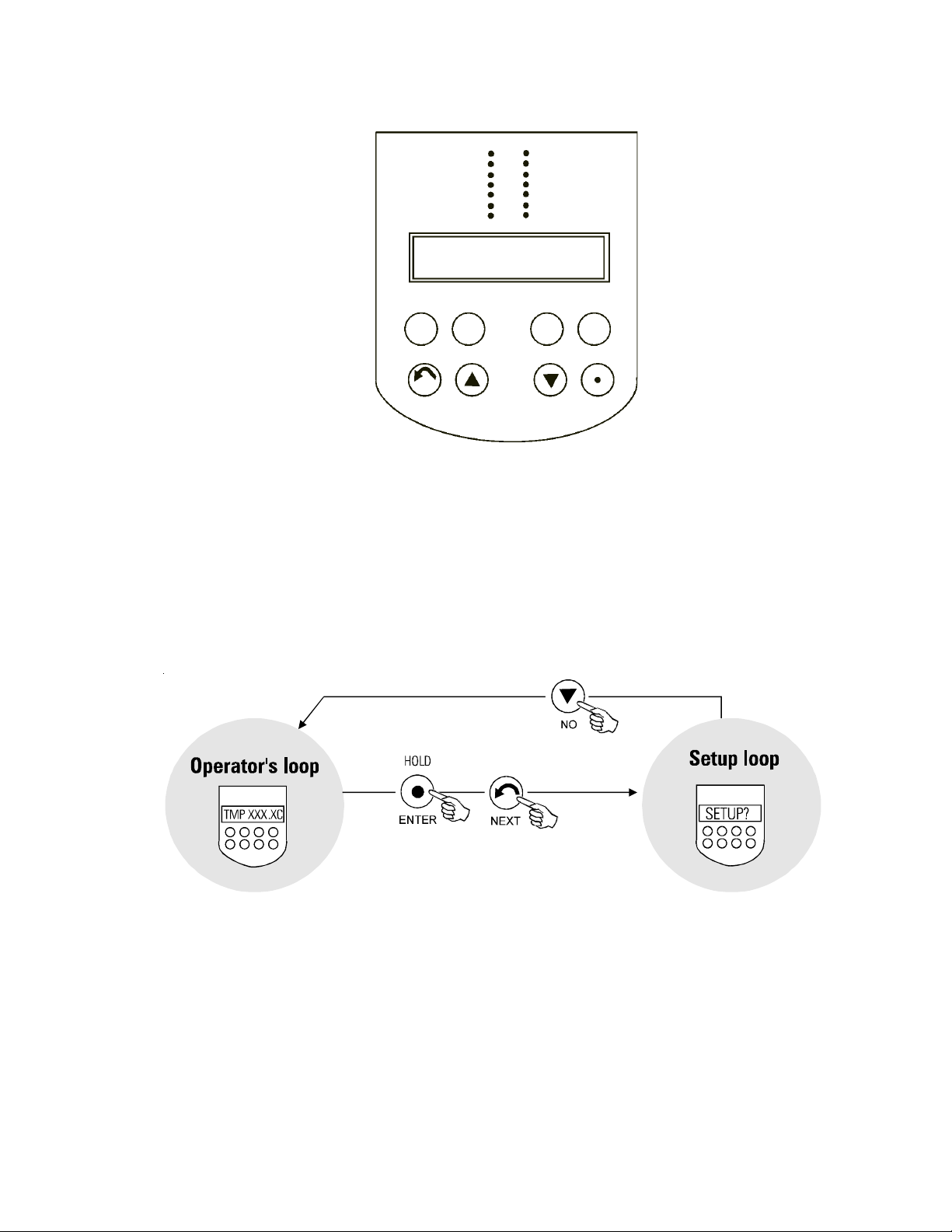
Controller Loo s
Two controller loops allow the operator to display and/or alter different
parameters of the controller. The loops can be accessed from the tempera-
ture display by pressing and holding the key combinations shown on Figure 1
below.
When the controller is first powered up it goes through a short self test and
then enters the Operator's Loop, displaying the reservoir fluid temperature.
HEAT ENABLE
COOL
PUMP
LOCAL
REMOTE
FLUID LEAK
LEVEL FAULT
EXT SENSOR
LOW FLOW
ADD FLUID
FILTER
BREAKERS
HIGH TEMP
HEAT
ON/OFF LOC/REM INT/EXT RESET
NEXT YES NO ENTER
RS485
Figure 1 Changing Loops
See page 14. See page 15.
Artisan Technology Group - Quality Instrumentation ... Guaranteed | (888) 88-SOURCE | www.artisantg.com
- 13 -
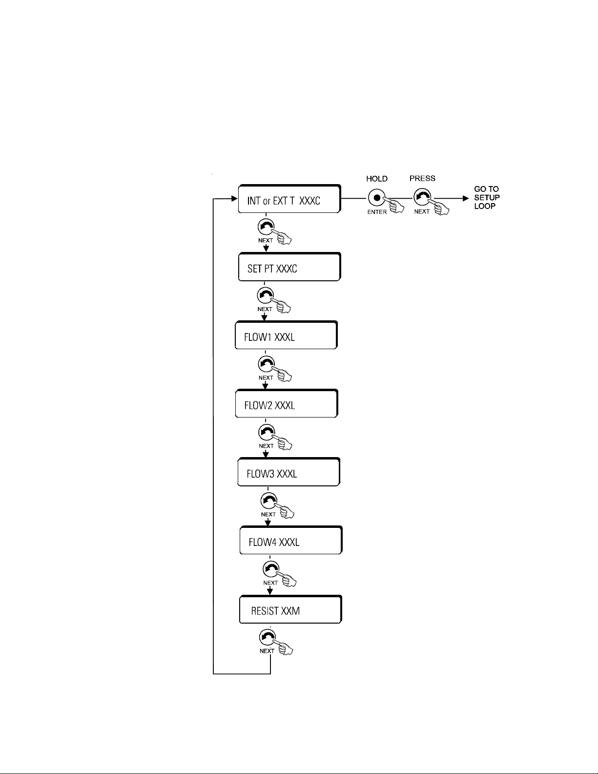
Operators Loop
When the controller is first powered it goes through a short self test and then
enters the Operator's Loop, displaying the reservoir temperature as measured
by either the internal or external RTD probe.
By pressing the NEXT key the controller will step through the menu shown
below.
YES key increments setpoint. NO key decrements
setpoint. See Changing a Value on page 20.
The display will flash while the setpoint is being
changed. The new value is not used by the
controller until the ENTER key is depressed.
Displays the flow rate of the individual circulation
loops in liters/minute. If the flow alarm is set to
zero (see Setup Loop) FLOW OFF will be
displayed instead.
Figure 2 Operator's Loop
This displays the resistivity of the bath fluid in
megohm-cm. Tenths will be display up to 9.9 meg.
10 - 20 meg will not display tenths. Resistivity is
maintained at or above the setpoint.
Artisan Technology Group - Quality Instrumentation ... Guaranteed | (888) 88-SOURCE | www.artisantg.com
- 14 -
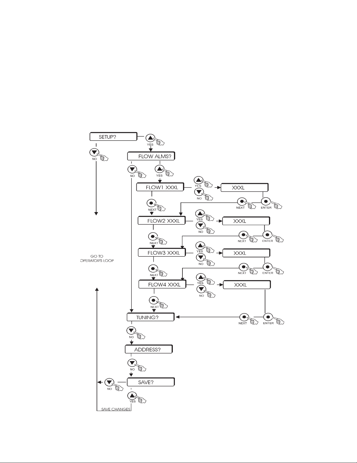
Figure 3 Setup Loop
Setup Loop
The Setup Loop allows the operator to change the flowrate setpoints. To enter this loop you
must be in the Operator's Loop and displaying the temperature. Depress and hold the
ENTER key while pressing the NEXT key. Follow the menu shown in Figure 3.
Each of the four flows can be set independently. The controller compares this value to the
actual flow of the circulation loop. If the actual flow drops below the alarm value, the
controller signals a low flow condition. If the alarm is set to zero, the flow checking for the
circulation loop will be disabled and the operators loop display will display FLOW X OFF.
Adjust values with the UP and DOWN arrows. See Changing a Value on page 20. Press
ENTER then NEXT for the controller to accept each new entry.
Only ualified technicians should change the
TUNING and ADDRESS values. Should you
inadvertently find yourself in either area of the
loop, press the NEXT key until the SAVE?
prompt is displayed. Press NO to abort all
changes. NOTE: This procedure will also restore
the flow alarms to their previous values.
Artisan Technology Group - Quality Instrumentation ... Guaranteed | (888) 88-SOURCE | www.artisantg.com

- 15 -
ERROR Messages
Error messages are displayed whenever certain conditions are detected.
When this occurs the error message will be displayed by alternating the error
message and the normal display. The keys and menus will perform normally.
All error messages, except for OVER TEMP, disappear when the error
condition is corrected. Corrective action for all error messages is listed in the
Maintenance Section of this manual.
PHASE ERR
This message is displayed whenever the controller senses a phase error or
missing phase coming into the unit. This condition will not allow the controller
to switch to ON.
24V OFF (Remote Mode Only)
This message is displayed whenever the controller looses the 24 volt input
signal from the tool. This signal loss turns off the unit and will not allow the
controller to switch to ON.
PUMP TRIP
This message is displayed whenever the controller senses the pump circuit
breaker has tripped.
PUMP OVRLD
This message is displayed whenever the controller senses a pump motor
overload condition.
HEAT TRIP
This message is displayed whenever the controller senses the heater circuit
breaker has tripped.
PUMP CNTL
This message is displayed whenever the controller senses a pump controller
error condition. This condition causes the heater to be disabled and turns off
the PUMP LED.
HEAT CNTL
This message is displayed whenever the controller senses a heat control
error condition. This condition disables the heater.
RTD FAIL
This message is displayed whenever the internal temperature probe has
failed, i.e. shorted or opened, and the probe is controlling (displaying) tem-
perature at the time of failure. This condition stops heating and cooling but the
pump continues to operate. This condition automatically resets.
OVER TEMP
This message is displayed whenever the controlling temperature, i.e. INT T or
EXT T, goes beyond 140°C. This condition will turn off the heat exchanger.
The unit will be in the standby mode and will not restart until power is cycled
to the controller.
Artisan Technology Group - Quality Instrumentation ... Guaranteed | (888) 88-SOURCE | www.artisantg.com

- 1 -
MODICOMM RS485 (CHX)
Interface
Author: Applied Materials.
Title: Heat Exchanger Serial Communication.
ID #: 0250-359 5.
Date: 2/28/97.
Revision: A.
Serial Communication
When the controller is in the ON mode, depressing the RS485 local/remote
pushbutton releases control of temperature setpoint to the MODICOMM
(CHX) interface. The interface can also be used to turn the unit on and off.
Outputs are provided for fluid level, fluid flow, resistivity and fluid temperature.
There are also digital outputs for fault summary and warning summary.
Serial Communication
S ecification
Connection Point
The RS-485 connector is a nine pin, metal shell D-connector with female
pins, mounted on the back of the unit with 4-40 threaded jack sockets. J4 and
J5 are connected in parallel to accommodate daisy chain: connections.
RS-485 connector pinout information
Pin 5 Ground
Pin 9 T+
Pin 1 T-
Configuration
Number of heat exchangers per heat exchanger controller 1
Base address (in 4X memory) for the input segment 0
Input segment size 9
Base address (in 4X memory) for the output segment 9
Output segment size
Optional Digital Input Points
Digital Input Point 1 Fluid level fault (1=fault, 0=OK)
Digital Input Point 2 Fluid flow fault (1=fault, 0=OK)
Digital Input Point 3 not used
Digital Input Point 4 not used
Digital Input Point 5 Fuse fault (1=fault, 0=OK)
Digital Input Point -32 reserved
Optional Analog Input Points
Analog Input Point 1 Fluid resistivity, engineering units are MOhm-cm
Analog Input Point 2 Fluid flow rate, engineering units are gpm
Analog Input Point 3-5 reserved
Number of Configurable Digital Input Points. 0
Number of Configurable Analog Input Points. 0
Number of Configurable Digital Output Points. 0
Number of Configurable Analog Output Points. 0
Artisan Technology Group - Quality Instrumentation ... Guaranteed | (888) 88-SOURCE | www.artisantg.com

- 17 -
Analog range values
These are scaling ranges only. The heat exchanger does not need to meet this range for operation.
Number Name eu_lo eu_hi
REQUIRED INPUT 1 Actual temperature - 0° C 1 0° C
OPTIONAL INPUT 1 Fluid resistivity 0 MW-cm 20 MW-cm
OPTIONAL INPUT 2 Fluid flow rate 0 GPM 10 GPM
REQUIRED OUTPUT Temperature set point - 0° C 1 0° C
Configurable Names NOT APPLICABLE
Configurable Terminology NOT APPLICABLE
Configurable Engineering Units NOT APPLICABLE
Heat Exchanger Controllers 4X memory map
4X Adrs. Description
100 Required Digital Inputs 1..2 (2 used; 14 not used)
101 Required Analog Input 1 (Actual temperature)
102 Optional Digital Inputs 1,2,5 (3 used; 2 not used; 11 reserved)
103 Optional Digital Inputs (1 reserved)
104 Optional Analog Input 1 ( Fluid resistivity)
105 Optional Analog Input 2 (Fluid flow rate)
10 ...108 Optional Analog Inputs (3 reserved)
109 Required Digital Output 1 (1 used; 15 not used)
10A Required Analog Output 1 (Temperature set point)
10B Optional Digital Outputs (1 reserved)
10C...10E Optional Analog Outputs (3 reserved)
Fault Summary (Digital Input Point 1 is the logical OR of these conditions): Fault condition shuts unit down.
Pump circuit breaker open fault
Pump overload fault
Pump TRIAC fault
Fluid major leak fault
Power phase error fault
Fluid low level fault
Fluid high temperature fault
Warning Summary (Digital Input Point 2 is the logical OR of these conditions)
Heater circuit breaker open warning
Heater TRIAC warning
Internal RTD warning
Fluid low flow warning
Reference
Applied Materials Serial Communication Specification No. 0250-359 5, 4/28/97 Rev. A.
Artisan Technology Group - Quality Instrumentation ... Guaranteed | (888) 88-SOURCE | www.artisantg.com
- 18 -
Section IV Operation
Pre Start U & Filling
Requirements
Whenever removing the fill cap or refilling the unit release any built up
pressure in the reservoir by opening the manual air bleed valve. When
refilling the heat exchanger should be running or the chamber uick
disconnects detached from the unit so fluid will not run back from the
lines or application to the reservoir and create an over-spill condition.
Ensure that the deionizer (DI) cartridge is installed and that the DI flow control
valve is in the OPEN position. NOTE: Use the flow meter, located on the rear of
the unit, to regulate flow control to meet your DI requirements.
Turn the main breaker on and the amber POWER LED will light. Turn the ON/
OFF rotary switch to ON.
Remove the 1¼" filler cap from the top of the reservoir. Using a funnel, carefully
fill the reservoir with recirculating fluid. If the units are stacked, the lower unit
will need a funnel with an extended flexible neck (due to the proximity of the
filter on the upper unit).
NOTE: Immediately stop filling when the ADD FLUID LED extinguishes.
Replace the filler cap on the reservoir. Also, close the manual bleed valve
located to the right of the tank fill fitting.
Depress the RESET button to remove the level fault and extinguish the LEVEL
FAULT LED.
The amount of recirculating fluid needed depends on the total requirements of
your system. Also, if substantial lengths of recirculating lines are used, add
enough fluid to compensate for their volume. The maximum reservoir volume is
5 gallons (19 liters).
NOTE: When refilling, the heat exchanger should be running or the chamber
quick disconnects detached from the unit so fluid will not run back from the
lines or tool to the reservoir to create an over-spill condition.
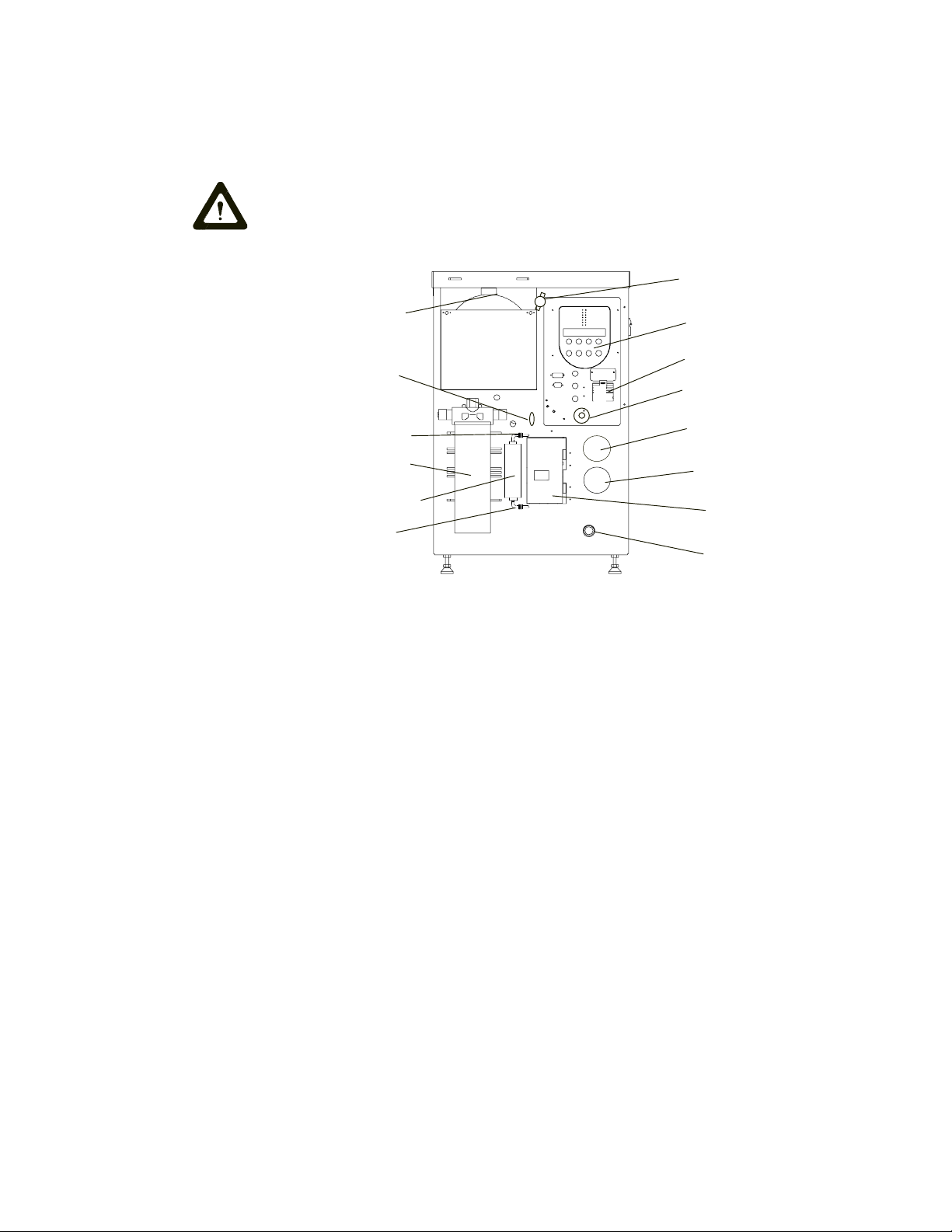
Control and Display
Filter
Tank Filler Cap
Air Bleed Valve
DI Cartridge
DI Flow Control Valve
Compression Fitting
Compression Fitting
Main Breaker with Lockout
EMERGENCY OFF
Filter Pressure Gauge
Recirculating Supply
Pressure Gauge
Flow Control
Access Door
Drip Pan Drain
Artisan Technology Group - Quality Instrumentation ... Guaranteed | (888) 88-SOURCE | www.artisantg.com
This manual suits for next models
1
Table of contents
Other Neslab Industrial Equipment manuals

Popular Industrial Equipment manuals by other brands


Siemens
Siemens 3VA9113-0RL21 operating instructions

Envirotainer
Envirotainer RKN e1 Operation manual

Staubli
Staubli MA275 Assembly instructions

Piranha
Piranha MegaFab P-120 Instructions and parts manual

Pfeiffer Vacuum
Pfeiffer Vacuum FullRange PKR 251 operating instructions

ITW
ITW Tapcon SA27 Operator's safety & operating instruction manual