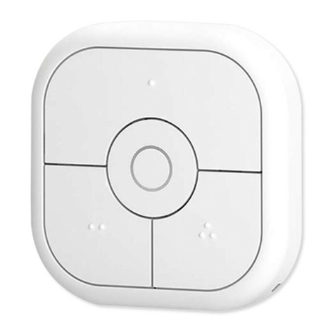
Smart Home Smart Switch
Welcome and thank you for purchasing a nestech smart switch. In order to
control your lights remotely, you’ll need to replace an existing switch with a
nestech smart switch. We hope you enjoy the convenience of nestech smart
switch!
Read the instruction carefully before starting the installation process
and keep them for future reference. This product must be installed by a
qualied electrician. A neutral wire will be required for the installation.
1. Before working on the product, disconnect the power supply and cover up
live parts in the working environment.
2. The glass panel can NOT be put on directly with the power on. Until you
have nished all the installation, then you can turn on the general power.
3. The Maximum Power is 600W/Gang. Do not overload to use this product.
.1Step Identify wires
Identify the wires that should be
connected to the terminal screws,
includes live, neutral and load wires
(see wiring diagram in section 5)
.3Step Wiring and x screws
Push wires rmly into L, N and L1
terminals respectively and tighten
terminal screws so that wires are
held securely. No bare wires should
protrude from the terminals. Ensure
correct wires are connect to the
correct terminals, if incorrectly wired,
this could damage the switch.
.2Step Remove the glass panel
of the smart switch
Using a small at screwdriver remove
the glass panel by placing the
screwdriver in the location notch on
the bottom part of the cover and twist
to unclip the cover.
Control Touch and remote controlled (RF 433MHz)
Cover Tempered crystal panel with RGB LED ind.
Input Voltage 250-110VAC 60/50Hz
Output power 600W per gang (Max.)
Lifetime 100,000 times at least (relay useful life)
Temperature -25 °C ~ +60 °C
Humidity ≤ %93
Dimensions 86 x 86 mm
Works with Fluorescent, Energy savers and LED bulbs
Standard CE, RoHS
Specications
Installation Procedure .4Step Install the switch on the wall box
. 1Method With wallbox screws
Carefully fold wires into wall box. Mount back box to wall box with screws
provided. Tighten screws just enough to hold back box in place. Do Not over-
tighten.
. 2Method With claws
Carefully fold wires into wall box. Mount back box to wall box with embedded
claws. Tighten claw screws just enough to hold back box in place. Do Not
over-tighten.
.5Step Re-attach the glass panel
Align the glass panel over the switch (A) and rmly
push (B) to click into place.
.6Step Power on
Once the power is on, touch the panel to turn on the
light.
Wall box screw
Back Box
Glass Panel
1/4
User Manual and
Installation Guide
Doc.Number : NSH-TX.-4ver1.0.0
