Page 6 of 12
939599284 Rev D
34
UNIVERSAL
BRACKET MOUNT
POWER OVER
ETHERNET CABLE
MOUNTING
BRACKET
#10-24 SCREW
#6-32 SCREW
WASHER
6a 6b
UNIVERSAL
BRACKET
COVER
POWER OVER
ETHERNET CABLE
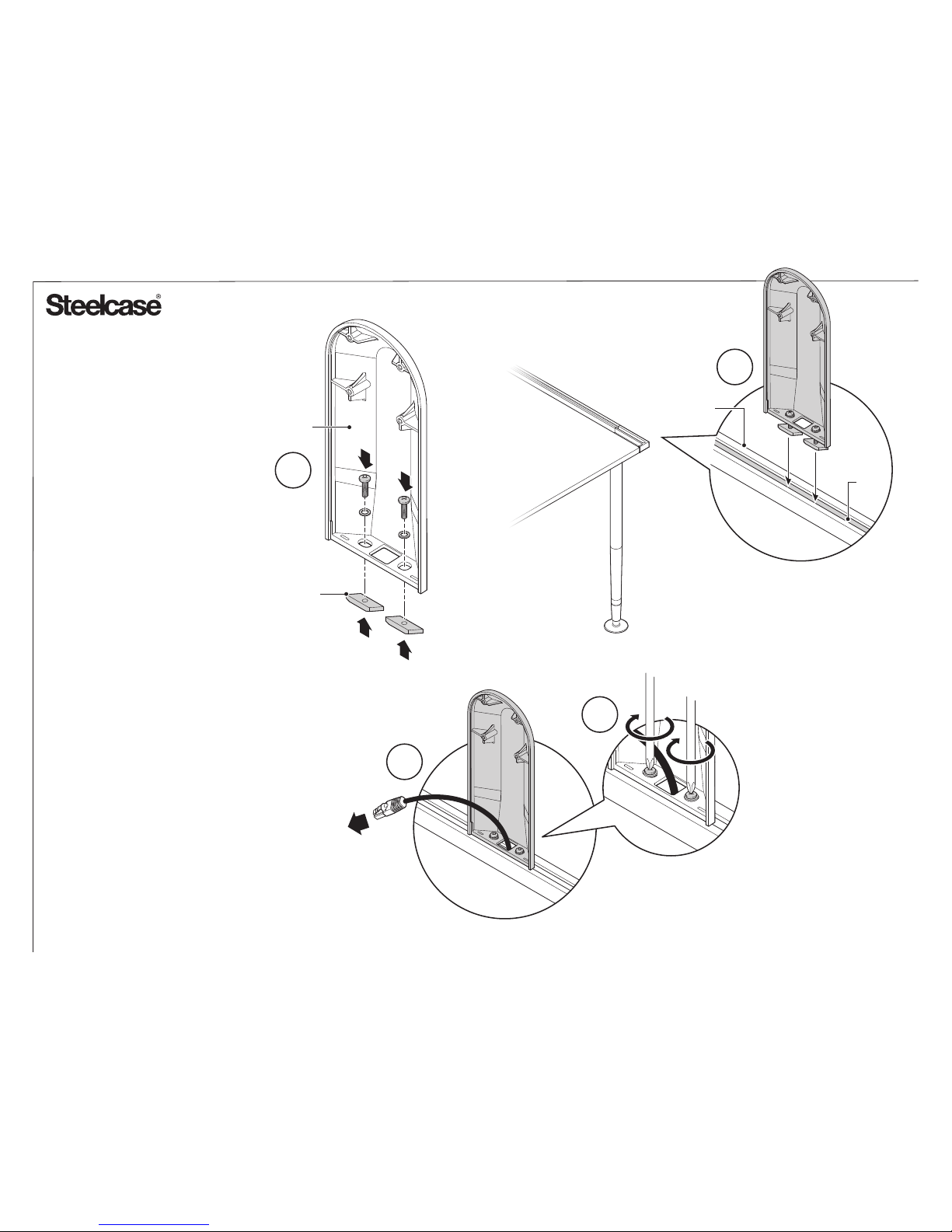
3. Align universal bracket mount with
holes in extrusion and holes in the
mounting plate which is positioned on
other side of extrusion.
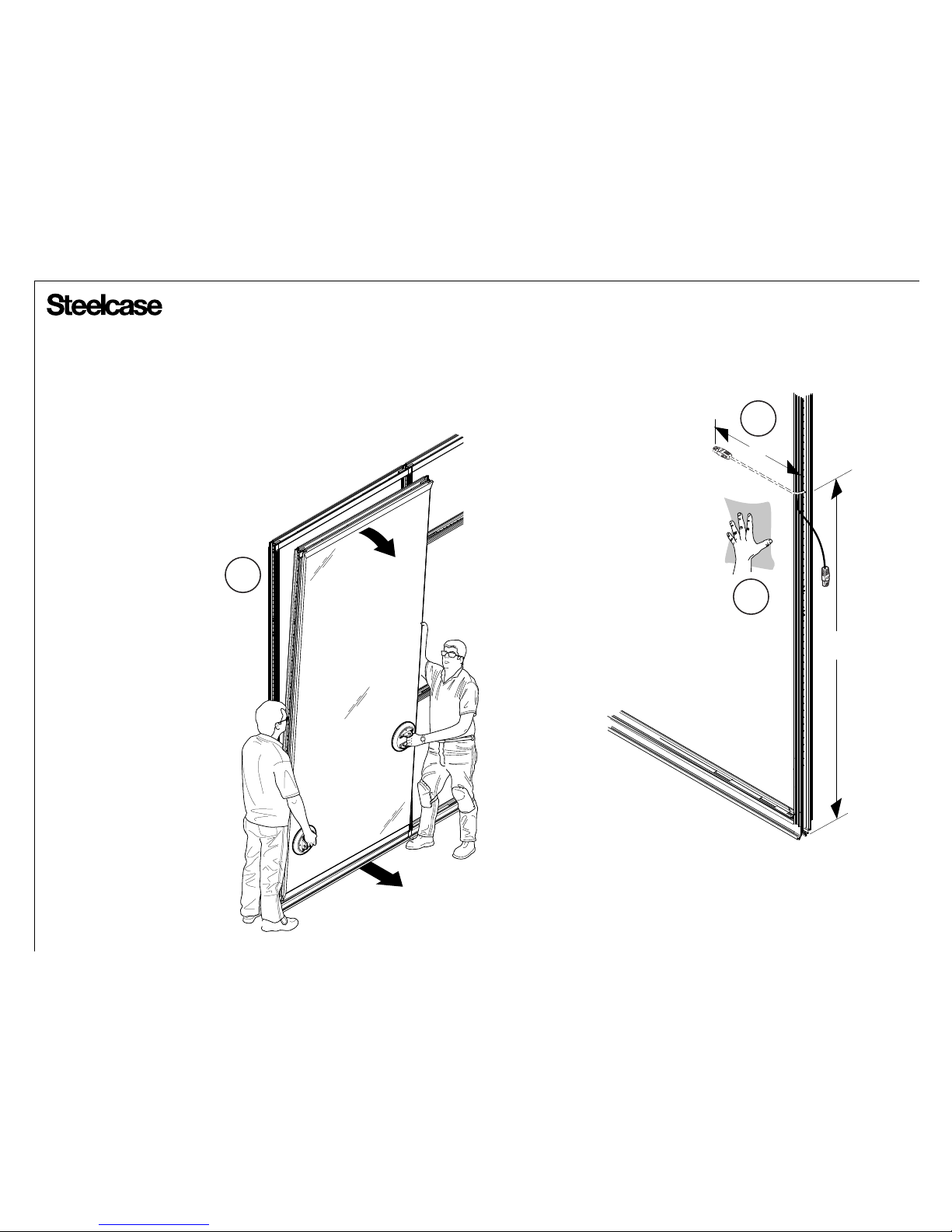
Route power over ethernet cable
through "U" shape in the mounting
plate, through 1/2" drilled hole in
extrusion and then through square
hole in bottom of universal bracket
mount.
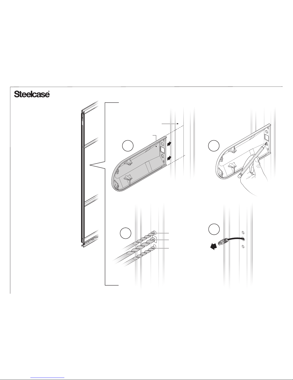
4. Attach universal bracket mount to
extrusion by inserting two (2) #10-24
screws with washers through holes in
universal bracket mount, holes in
extrusion and holes in mounting
bracket.
5. Level RoomWizard II and adjust
screws if necessary.
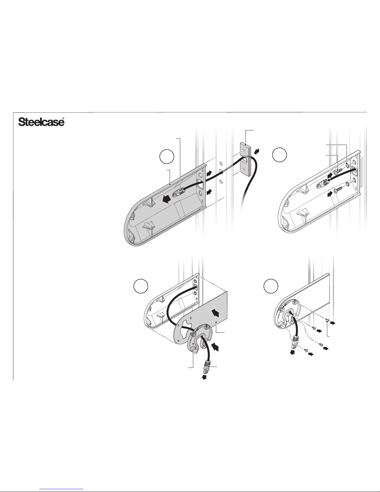
6. Align universal bracket and puck
with the universal bracket mount.
Route power over ethernet cable
through universal bracket cover and
puck (6a).
Attach universal bracket cover and
puck to universal bracket mount using
the four (4) provided #6-32 machine
screws with a #2 Phillips head
screwdriver (6b).
7. Refer to RoomWizard II installation
quickstart guide for remaining
assembly. MOUNTING
PUCK