Rose electronics REMOTE CONTROL PANEL User manual

REMOTE CONTROL PANEL
REMOTE CONTROL PANELREMOTE CONTROL PANEL
REMOTE CONTROL PANEL
10707 Stancliff Road Phone: (281) 933-7673
Houston, exas 77099 WWW.ROSE.COM
INSTALLATION
AND
OPERATIONS MANUAL

LIMITED WARRANTY
Copyright 2004, Rose Electronics. All rights reserved.
No part of this manual may be reproduced, stored in a retrieval system, or transcribed in any form or any
means, electronic or mechanical, including photocopying and recording, without the prior written permission of
Rose Electronics.
Rose Electronics Part # MAN-RCP
Printed In the United States of America - Revision 1.0
Rose Electronics
®
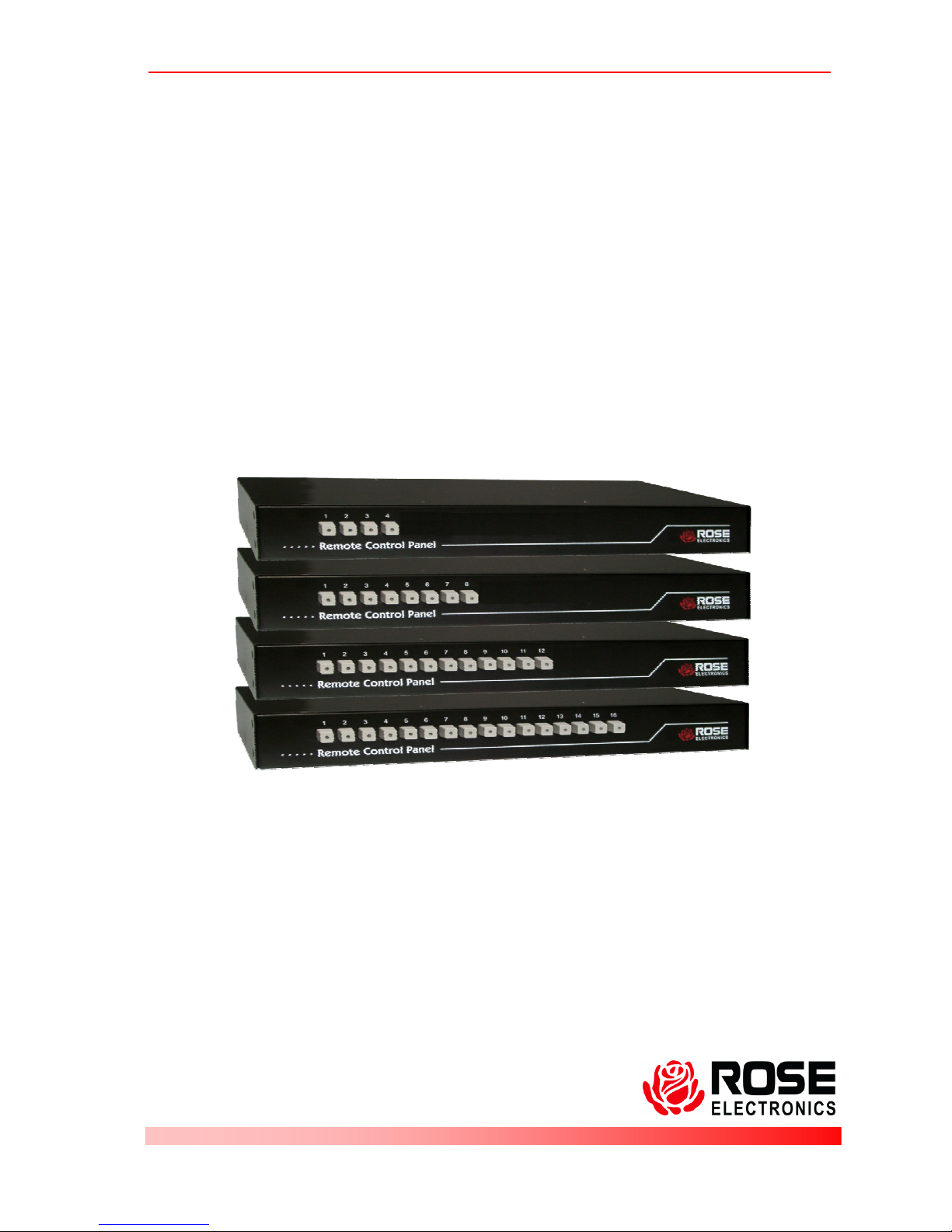
warrants the Remote Control Panel™ to be in good working order for one year from
the date of purchase from Rose Electronics or an authorized dealer. Should this product fail to be in
good working order at any time during this one-year warranty period, Rose Electronics will, at its
option, repair or replace the Unit as set forth below. Repair parts and replacement units will be either
reconditioned or new. All replaced parts become the property of Rose Electronics. his limited
warranty does not include service to repair damage to the Unit resulting from accident, disaster, abuse,
or unauthorized modification of the Unit, including static discharge and power surges.
Limited Warranty service may be obtained by delivering this unit during the one-year warranty period to
Rose Electronics or an authorized repair center providing a proof of purchase date. If this Unit is
delivered by mail, you agree to insure the Unit or assume the risk of loss or damage in transit, to
prepay shipping charges to the warranty service location, and to use the original shipping container or
its equivalent. You must call for a return authorization number first. Under no circumstances will a unit
be accepted without a return authorization number. Contact an authorized repair center or Rose
Electronics for further information.
ALL EXPRESS AND IMPLIED WARRAN IES FOR HIS PRODUC INCLUDING HE WARRAN IES
OF MERCHAN ABILI Y AND FI NESS FOR A PAR ICULAR PURPOSE, ARE LIMI ED IN
DURA ION O A PERIOD OF ONE YEAR FROM HE DA E OF PURCHASE, AND NO
WARRAN IES, WHE HER EXPRESS OR IMPLIED, WILL APPLY AF ER HIS PERIOD. SOME
S A ES DO NO ALLOW LIMI A IONS ON HOW LONG AN IMPLIED WARRAN Y LAS S, SO
HE ABOVE LIMI A ION MAY NO APPLY O YOU.
IF HIS PRODUC IS NO IN GOOD WORKING ORDER AS WARRAN IED ABOVE, YOUR SOLE
REMEDY SHALL BE REPLACEMEN OR REPAIR AS PROVIDED ABOVE. IN NO EVEN WILL
ROSE ELEC RONICS BE LIABLE O YOU FOR ANY DAMAGES INCLUDING ANY LOS PROFI S,
LOS SAVINGS OR O HER INCIDEN AL OR CONSEQUEN IAL DAMAGES ARISING OU OF
HE USE OF OR HE INABILI Y O USE SUCH PRODUC , EVEN IF ROSE ELEC RONICS OR
AN AU HORIZED DEALER HAS BEEN ADVISED OF HE POSSIBILI Y OF SUCH DAMAGES, OR
FOR ANY CLAIM BY ANY O HER PAR Y.
SOME S A ES DO NO ALLOW HE EXCLUSION OR LIMI A ION OF INCIDEN AL OR
CONSEQUEN IAL DAMAGES FOR CONSUMER PRODUC S, SO HE ABOVE MAY NO APPLY
O YOU. HIS WARRAN Y GIVES YOU SPECIFIC LEGAL RIGH S AND YOU MAY ALSO HAVE
O HER RIGH S WHICH MAY VARY FROM S A E O S A E.
NO E: his equipment has been tested and found to comply with the limits for a Class A digital device,
pursuant to Part 15 of the FCC Rules. hese limits are designed to provide reasonable protection
against harmful interference when the equipment is operated in a commercial environment. his
equipment generates, uses, and can radiate radio frequency energy and, if not installed and used in
accordance with the instruction manual, may cause harmful interference to radio communications.
Operation of this equipment in a residential area is likely to cause harmful interference in which case
the user will be required to correct the interference at his own expense.
IBM, A , and PS/2 are trademarks of International Business Machines Corp. Microsoft and Microsoft
Windows are registered trademarks of Microsoft Corp. Any other trademarks mentioned in this manual
are acknowledged to be the property of the trademark owner.

EUROPEAN UNION DECLARATION OF CONFORMITY
ACCORDING TO COUNCIL DIRECTIVE 89/336EEC & 73/23EEC
his equipment is in conformity with the
protection requirements of the following
Council Directives:
he Declaration of Conformity is based upon
compliance of the product with the following
harmonized standards:
EN55022: 1998 EN61000-4-5: 199
5
EN55024: 1998 EN61000-4-6: 1996
EN61000-4-2: 1995 EN61000-4-11: 1994
EN61000-4-3: 1995 EN60950: 2000
EN61000-4-4: 1995

INTRODUCTION
Disl imer
While every precaution has been taken in the preparation of this manual, the
manufacturer assumes no responsibility for errors or omissions. Neither
does the manufacturer assume any liability for damages resulting from the
use of the information contained herein. he manufacturer reserves the right
to change the specifications, functions, or circuitry of the product without
notice.
he manufacturer cannot accept liability for damages due to misuse of the
product or other circumstances outside the manufacturer’s control. he
manufacturer will not be responsible for any loss, damage, or injury arising
directly or indirectly from the use of this product.
System introduction
hank you for choosing the Rose Electronics
Remote Control Panel for
your remote KVM switching application. he Remote Control Panel is the
results of Rose Electronics commitment to provide solid, practical switching
solutions for today's business world. he Remote Control Panel connects
directly to the RS232 serial port on a KVM switch allowing you to remotely
switch to any CPU port.
he Remote Control Panel is easy to install and operate. No set-up is
required; just connect a Rose Electronics UltraView, ServeView, or
MultiVideo product to the Remote Control Panel with an RJ11 cable, apply
power and push the button. If you push button #5 on the Remote Control
Panel, the CPU connected to port 5 on the KVM switch will connect to the
KVM port and display on the KVM station.

Models
4-Button
8-Button
12-Button
16-Button
Rear View (All Models)
Connectors – RS232
Power
Inst ll tion
he Remote Control Panel is easy to install.
Connect a serial cable from your KVM switch’s RS232 port to the
Remote Control Panel’s rear RS232 port
Connect the power adapter to the unit
Connect the power adapter to 110/220 v source
It is ready to use. No setup or configuration is needed.

C bles
A serial adapter cable is used to connect the Remote Control Panel to the
RS232 port on a compatible KVM switch. he DB9M to RJ11 cable
connects from the DB9M connector on the Remote Control Panel to the
RS232 port on the KVM switch. Extended distance cables are offered for
distances greater than 5 feet from the Remote Control Panel.
Oper tion
Operating the Remote Control Panel is as easy as pushing a button. If you
want the KVM station to switch to CPU port 5, just push button #5.
Immediately the KVM station will switch to CPU port #5 and that computer’s
video will display.
Part numbers
Part numbers Part numbers
Part numbers
Model
RCP-16RS 16 switch model
RCP-12RS 12 switch model
RCP-8RS 8 switch model
RCP-4RS 4 switch model
ACC-A RX Serial adapter, RJ11 to DB9F
CAB-04RJnnn RJ11 cable
(nnn = length in feet)
RM-UL19 19” Rack mount kit
RM-UL23 23” Rack mount kit
RM-UL24 24” Rack mount kit
Specifications
SpecificationsSpecifications
Specifications
Width Depth Height Weight
Dimensions 13.2 4.5 1.75 in 4lbs
33.5 11.4 4.45 cm 1.8kg
Connectors RS232 - DB9M
Power - DIN5 Indicators
Indicators CPU port selection LED
Chassis Electro galvanized steel,
black powder coated
emp 0° – 45°C / 32°F – 113°F
Humidity 5% – 80% non-condensing RH
Approvals CE


〒103-0014
東京都中央区日本橋蛎殻町 1-16-11
TEL:03-3668-8089 FAX:03-3668-9872
URL:http://www.cybernetech.co.jp
Table of contents
Popular Network Accessories manuals by other brands

QUNDIS
QUNDIS RNN5 Operating and installation instructions

Valcom
Valcom VIP-801 user guide

Patton electronics
Patton electronics Patton SmartNode 2400 Series user manual

METRObility Optical Systems
METRObility Optical Systems R711-11 Installation & user guide

Clearfield
Clearfield FieldShield StrongFiber installation manual

Coremorrow
Coremorrow S51.ZT2S-C1 user manual