Net2Edge Liberator CE User manual

QSG
Quick Start Guide:
LIB-225
Quick Start guide for Liberator™ CE

Net2Edge | Liberator™ CE Quick Start Guide
2
Trademarks
All trademarks and registered trademarks are the property of their respective owners.
Copyright Notice/Restrictions
Copyright © 2016 Net2Edge Limited all rights reserved.
No part of this work may be reproduced or used in any form or by any means (graphic, elec-
tronic or mechanical) without written permission from Net2Edge.
The information contained herein is confidential property of Net2Edge Limited. The use, copy-
ing, transfer or disclosure of such information is prohibited except by express written agree-
ment with Net2Edge Limited.
Revision History
Rev
Date
Description
A
1
st
July 2015
Initial Release
B
6
th
April 2016
Re-Branded and Re-issued
C
20
th
April 2016
Updated to include latest VLAN update

Net2Edge | Liberator™ CE Quick Start Guide
3
Contents
Trademarks.......................................................................................................................2
Copyright Notice/Restrictions............................................................................................2
Revision History ................................................................................................................2
1. Introduction ................................................................................................................4
2. Applications................................................................................................................4
3. Features.....................................................................................................................4
4. Initial Configuration / Setup........................................................................................5
4.1 Local IP Address / Subnet Mask / Default Gateway.............................................5
4.1.1. CLI Connection..............................................................................................5
4.1.2. Web UI Connection........................................................................................6
4.2. Single IP vs Dual IP addressing...........................................................................7
4.2.1 VLAN Settings ...............................................................................................8
4.3. Setting up a logical link.........................................................................................9
4.4. Setting up the port and allocating channels........................................................11
4.5. Clocking Configuration.......................................................................................12
5. Cable Pinouts...........................................................................................................14
6. Contacts...................................................................................................................17

Net2Edge | Liberator™ CE Quick Start Guide
4
1. Introduction
The Liberator™™ CE combines Circuit Emulation functionality with Carrier Ethernet
capabilities, which allows the user to transmit TDM data across a packet switched network.
2. Applications
The Liberator™ CE units need to be configured in order to communicate and work with
each other. The setup requires a minimum of 2 units to set a communication link (or Logical
link as referred to in the units’ management menu).
3. Features
The Liberator™ has the following Hardware Features:
•3 x 1Gb packet ports (front panel)
•2 x SFP cages (front panel)
•1 x TDM port (front panel)
•1 x Smart serial port (front panel)
•1 x console port (rear panel)
•1 x management USB port (rear panel)
•1 x alarm port (rear panel)

Net2Edge | Liberator™ CE Quick Start Guide
5
4.Initial Configuration / Setup
4.1 Local IP Address / Subnet Mask / Default Gateway
The Liberator™ CE can be configured initially by connecting using either the CLI interface or via
a web browser using the default IP address: 192.168.0.1
It is recommended to connect via the CLI interface in the first instance to verify the IP address
set up on the unit.
4.1.1. CLI Connection
First you will need to connect to the unit’s MGMT port (located on the rear panel) using a
standard USB A-B cable (a standard printer cable will also suffice).
Once connected, your PC / laptop should have allocated a COM port to the cable – you will
need this COM number for connecting to the box so it is advised you find this by going via the
Control Panel / Device manager menu on your machine (computers running Windows® only).
Next you will need to use terminal emulation software to connect to the units CLI interface –
this can be either HyperTerminal or PuTTY.
Once connected, you will need to enter the default login details as below:
User: admin
Pwd: <blank>
To verify the IP address, type in the following command:
Show IP interface brief
This should show you the current IP setup on the device; as well whether it is static or
dynamically generated.
Once you have the IP, you can use a web browser to access the Web User Interface. If there is
no IP set then an IP address can be assigned, as follows:
Firstly you must put the unit into configuration mode by typing the following:
Configure Terminal
Interface Vlan 1

Net2Edge | Liberator™ CE Quick Start Guide
6
Next either set up a static IP address can be assigned or the DHCP client enabled with a fallback
IP address as well.
To establish a static IP address, type in the following:
IP Address <IPV4 address> <subnet mask>
To enable DHCP and a fallback IP address, type the following:
IP address dhcp fallback <IPV4 address> <subnet mask>
4.1.2. Web UI Connection
Access to the unit’s management system can be gained from its IP address - simply enter the IP
address into the address bar of a web browser – if your computer is on the same subnet as the
Liberator™ CE, then the browser should ask for login details.
Enter ‘Admin’ as a username and leave the password blank to access the UI.
Once the management system has been accessed, the unit’s IP address, subnet mask and
gateway address can be changed by going to the following submenu:
Configuration > System > IP
From there you can modify the IP details – please note that if you change the IP address, you
will then have to close your web session and open a new one with the new IP.
PLEASE NOTE: Any changes you make, you will have to ensure they are saved as a
running config – otherwise these changes will be lost once the unit has been powered
down. To save the config you must go to the following submenu:
Maintenance > Configuration > Save startup-config

Net2Edge | Liberator™ CE Quick Start Guide
7
4.2. Single IP vs Dual IP addressing
The Liberator™ CE supports Dual IP addresses – this means that it can maintain one IP for access-
ing the unit’s management UI and a separate IP for CES data. By default the unit will be set to a
Single IP set up which means you can use the same IP for management and CES traffic
To configure the CES IP you must go to the following submenu:
Configuration > CES > Protocol
Under Local IPv4 address you can enter your preferred IP for the TDM data traffic to use; this
should also be followed with the subnet mask length under the IPv4 prefix.
Please note:
•If you are going to use the Single IP set up, then you should do the following:
oThe Local IPv4 address must be the same as the management IP you are using
oAllow Management on CES IP should be set to ‘Yes’
•If you are going to use the Dual IP set up, then you should do the following:
oThe Local IPv4 address must be on a different subnet to the management IP
oAllow Management on CES IP can be set to either ‘No’ or ‘Yes’ – if set to Yes then
the unit GUI can be accessed by either the management IP or the CES IP.

Net2Edge | Liberator™ CE Quick Start Guide
8
4.2.1 VLAN Settings
In the dual IP scenario, it will be necessary to set up a new IP (VLAN) interface for the CES IP –
please note that even in a single IP scenario, if you are not planning on using VLAN 1 then you
will need to set up a different VLAN interface as well.
To set up a new VLAN interface you will need to do the following:
•Go to the Configuration > System > IP page
Once there, you can click on the Add Interface button which will allow you to add a new IP in-
terface. Please note:
•You can only have one Interface per subnet
•You can’t use the same VLAN ID twice
Net2Edge | Liberator™ CE Quick Start Guide
9
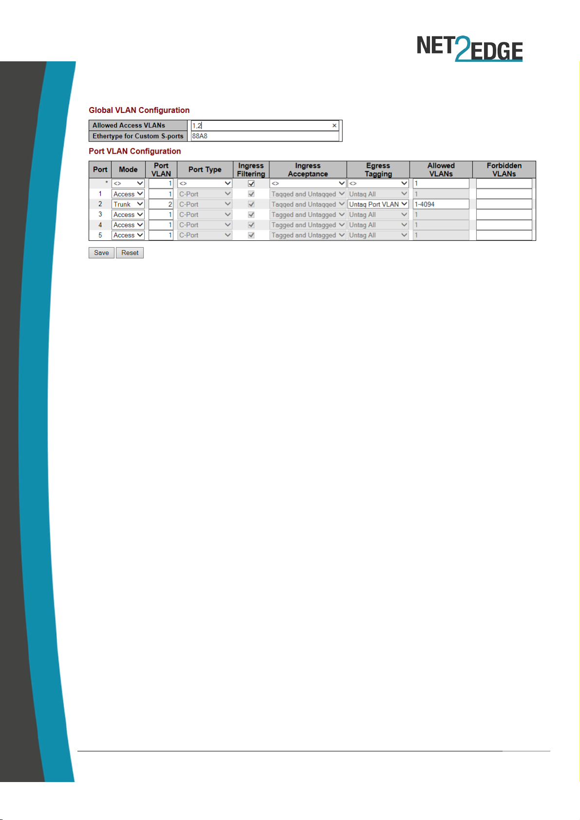
Once the new interface is set up, you will have to configure the port VLAN settings to complete
the process. To do this you must go to Configuration > VLANs.
•For the management traffic the port you intend to use should be set to ‘Access’ – the
‘Port VLAN’ field should contain the ID you set up under the IP interface. Please ensure
that you add the VLAN ID to the ‘Allowed Access VLANs’ field at the top of the page
•In the event you are using Dual IP and have a separate IP interface set up for the CES
traffic, you will need to set the port you want to use to the following;
oMode: Trunk
oPort VLAN: <ID you used to set up the IP interface>
oPort Type: C-Port (can’t be changed under this Mode)
oIngress Filtering: Selected (can’t be changed under this Mode)
oIngress Acceptance: Tagged and Untagged (can’t be changed under this Mode)
oEgress Tagging: Untag Port VLAN
oAllowed VLANs: 1-4094 (this can be shortened to match your VLAN ID)
Please note: If you need to customise the port type or the Ingress filtering and acceptance,
you can do so by setting the mode to ‘Hybrid’.
4.3. Setting up a logical link
To use the Circuit Emulation features, the first setup step is to set up a logical link between a
minimum of two PacketBand units – this link will carry the TDM data across a packet switching
network.
To do this you must go to the logical link sub menu which is located here:
Configuration > CES > Link > Settings
Net2Edge | Liberator™ CE Quick Start Guide
10
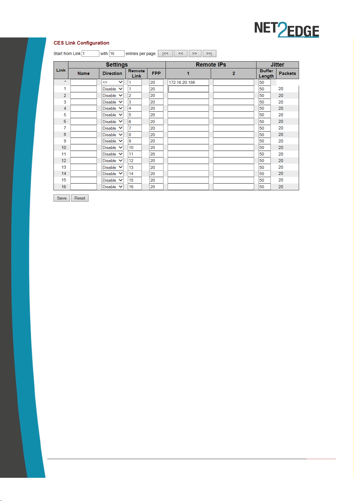
From here you can assign a name to the logical link and set up the destination address
(Remote IP) for the unit with which you are trying to set up a link. Please ensure:
- You enter the destination under Remote IP column 1
- The IP you use is the local IP set up under Protocol (See section 4.2)
- You enable the direction so the link is active
Once you are satisfied with the link, click on the save button to commit your changes. This
setup must be repeated on the destination box (using the originator’s IP address under the
Remote IP box) to complete the setup.
Please ensure that the Link numbers (first column) match up on both boxes – i.e. if you set up
the link under link 3, then you must do the same on the destination box.
PLEASE NOTE: As mentioned above, please ensure you save your running configuration
otherwise your changes will be lost once the unit has been powered down.

Net2Edge | Liberator™ CE Quick Start Guide
11
4.4. Setting up the port and allocating channels
The Liberator™ CE can be configured to work on an E1 or a T1 network presentation, with
additional options that allow you to set up the connection as a Full or Fractional configuration.
To access these options, you must go to the following submenu:
Configuration > CES > Port Settings
Once you’ve selected your network presentation, you can set the number of channels you wish
to allocate to the logical links – to be functional; each logical link must have a minimum of one
channel.
To configure this you can either click on the ‘Channel Selection’ link on the port settings page
or you can go directly to the following submenu:
Configuration > CES > Link > Channel Selection
Depending on the network presentation required, you can allocate a maximum of 31 channels
(E1) or 24 (T1) under the Fractional configuration. If you require the Full Configuration then you
can just enter a tick under the Port column.

Net2Edge | Liberator™ CE Quick Start Guide
12
4.5. Clocking Configuration
The final setup step is to configure the priorities of your clocking source – the Liberator™ CE
offers the following options:
•You can receive clock from the units own internal clock (by leaving all priorities as 19)
•You can receive clock from either the TDM or the Serial port (where available)
•You can receive clock from a logical link
To access the clock priorities submenu, you should go to the following:
Configuration > CES > Clock Priorities
The lowest number (0) indicates the highest priority, whereas the highest (19) indicates the
lowest priority. The unit will attempt to use the highest priority clock first and, if it can’t get a
stable connection, it will move to the next priority in the list until it eventually gets a stable
clock connection.
In a scenario where there is a Liberator™ unit at each end of a logical link with no external clock
source, then you should set one unit to clock from its internal clock (making it the Master) and
the set the second unit to clock from the logical link (making it the slave). You can verify the
clock connection by going to:
Monitor > CES > Clocking > Summary

Net2Edge | Liberator™ CE Quick Start Guide
13
The Status column shows the state of the clocking data transmission:
•Freerun: Clock isn’t synchronised with any source or destination
•Acquiring: Clock source has been identified and is in the process of synchronising
•Acquired: Clock source has been synchronised and locked
•Holdover: Clock data is using the last known value as insufficient data is being received
from the source/destination.
Net2Edge | Liberator™ CE Quick Start Guide
14
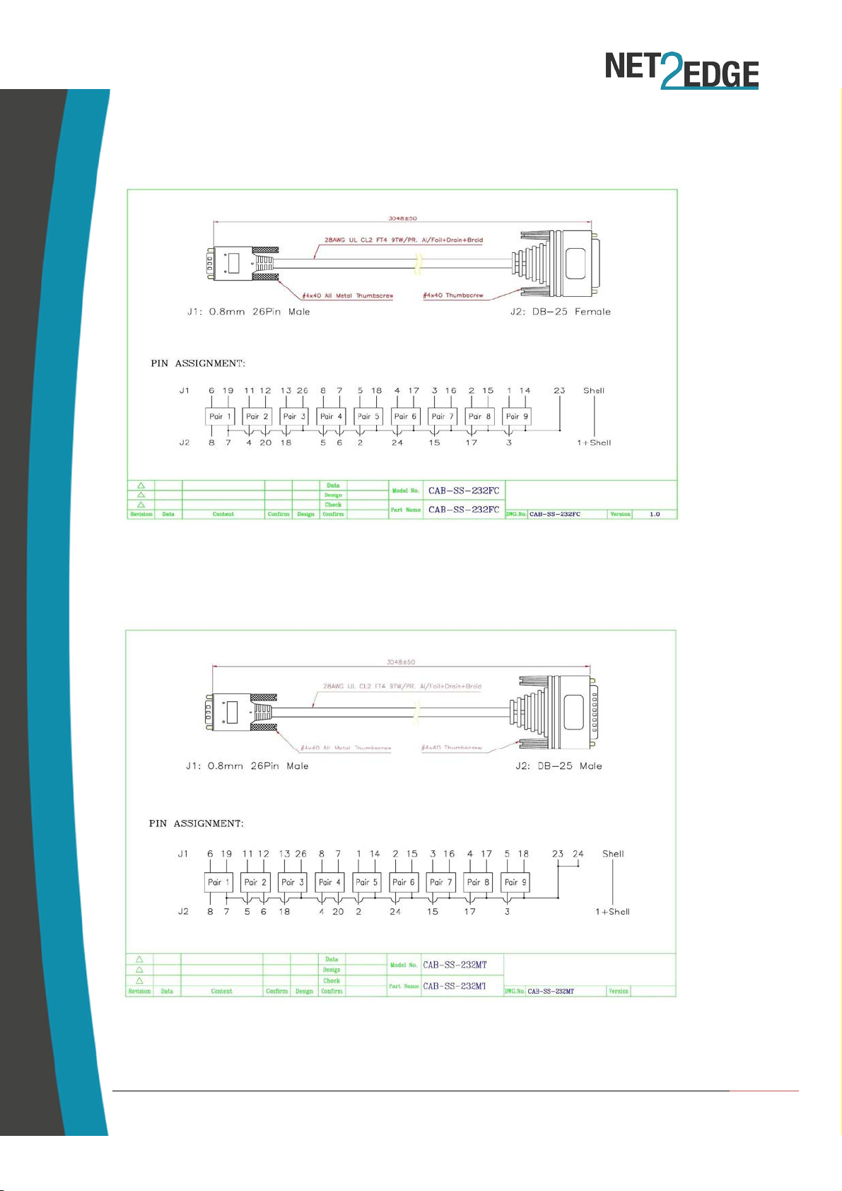
5.Cable Pinouts
RS-232 FM
RS-232 M

Net2Edge | Liberator™ CE Quick Start Guide
15
V35 M
V35 FM
Net2Edge | Liberator™ CE Quick Start Guide
16
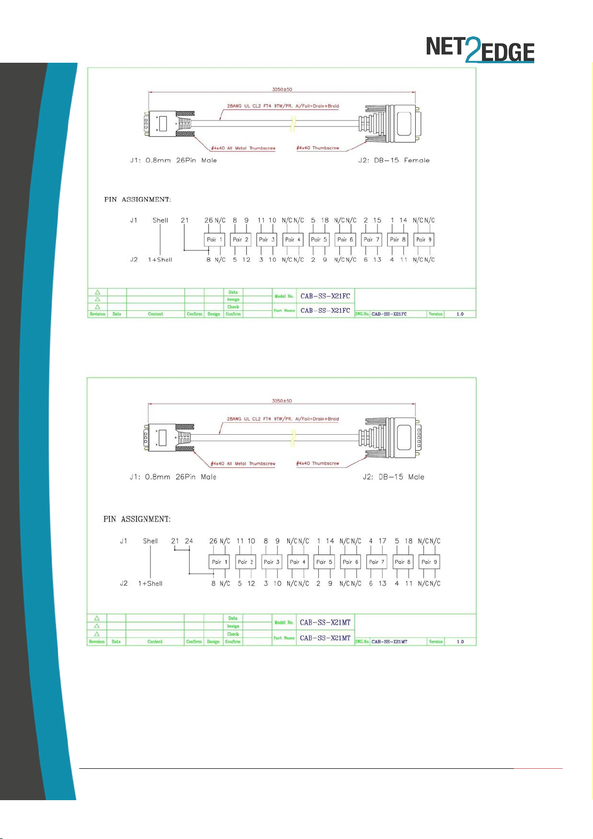
X21 FM
X21 M

Net2Edge | Liberator™ CE Quick Start Guide
17
6.Contacts
Corporate Headquarters
Net2Edge Limited
Passfield Oak
LIPHOOK
Hampshire
GU30 7RL
United Kingdom
tel: +44 345 013 0030
liberator@net2edge.com.com
www.net2edge.com
This manual suits for next models
1
Table of contents
Popular Recording Equipment manuals by other brands


IntesisBox
IntesisBox TO-RC-MBS-1 installation instructions

Avid Technology
Avid Technology Pro Tools S6 Master Post Module Networking guide

PRESONUS
PRESONUS STUDIOLIVE - SCHEMA manual

Balluff
Balluff BNI IOL-719-002-Z012-C10 user guide

HomeMatic
HomeMatic HM-Swl-3-FM Installation and operating manual

Iso-Max
Iso-Max SC-2NR user guide


