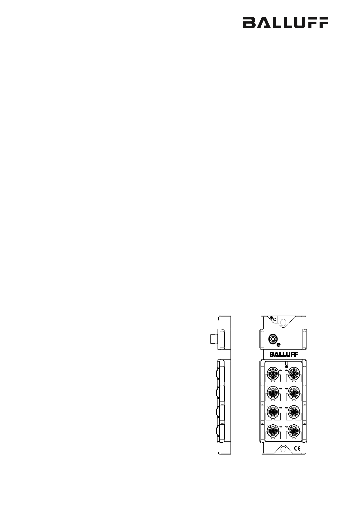
Balluff Network Interface / IO-Link BNI IOL-719-002-Z012-XXX
www.balluff.com
2 Safety
This guide describes the Balluff Network Interface BNI IOL-719-002-Z012-XXX for the
application as peripheral analog input module to establish connection of
RTDs and thermocouple sensors. Hereby it is about an IO-Link device which communicates
by means of IO-Link protocol with the superordinate IO-Link master assembly.
startup
Attention!
Installation and startup are to be performed only by trained specialists. Qualified
personnel are persons who are familiar with the installation and operation of the
product, and who fulfills the qualifications required for this activity. Any damage
resulting from unauthorized manipulation or improper use voids the manufacturer's
guarantee and warranty. The Operator is responsible for ensuring that applicable
of safety and accident prevention regulations are complied with.
notes
Commissioning and inspection
Before commissioning, carefully read the operating manual.
The system must not be used in applications in which the safety of persons is dependent on
the function of the device.
Authorized Personnel
Installation and commissioning may only be performed by trained specialist personnel.
Intended use
Warranty and liability claims against the manufacturer are rendered void by:
•Unauthorized tampering
•Improper use
•Use, installation or handling contrary to the instructions provided in this operating
manual
Obligations of the Operating Company
The device is a piece of equipment from EMC Class A. Such equipment may generate RF
noise. The operator must take appropriate precautionary measures. The device may only be
used with an approved power supply. Only approved cables may be used.
Malfunctions
In the event of defects and device malfunctions that cannot be rectified, the device must be
taken out of operation and protected against unauthorized use.
Intended use is ensured only when the housing is fully installed.
Aggressive
Substances
Attention!
The BNI modules always have good chemical and oil resistance. When used in
aggressive media (such as chemicals, oils, lubricants and coolants, each in a
high concentration (i.e. too little water content)), the material must first be
checked for resistance in the particular application. No defect claims may be
asserted in the event of a failure or damage to the BNI modules caused by such
voltage
Attention!
Disconnect all power before servicing equipment.
In the interest of product improvement, the Balluff GmbH reserves the right to
change the specifications of the product and the contents of this manual at any