NetApp 42U 1280 mm System Cabinet User manual


Contents
Preparing to install the system cabinet ....................................................... 4
System cabinet features ............................................................................................... 4
Required tools and equipment ..................................................................................... 6
Space requirements and system cabinet dimensions ................................................... 6
Supported PDU types and specifications .................................................................... 8
Unpacking the system cabinet ..................................................................... 9
Installing a system cabinet ......................................................................... 10
Installing the cabinet interconnect kit ....................................................................... 10
Installing the bolt-down kit ....................................................................................... 15
Installing additional support rails .............................................................................. 16
Installing equipment in the system cabinet ............................................................... 18
Powering on the system cabinet ................................................................................ 19
Replacing PDUs .......................................................................................... 21
Reversing the system cabinet front door .................................................. 22
Removing the illuminated badge ............................................................................... 23
Removing the system cabinet door ........................................................................... 24
Moving the badge power supply and cabling ............................................................ 24
Reversing the door hinge and lock catch ................................................................... 27
Reinstalling the door and illuminated badge ............................................................. 29
Reinstalling the system cabinet door ............................................................. 29
Reinstalling the illuminated badge ................................................................ 30
Copyright information ............................................................................... 31
Trademark information ............................................................................. 32
How to send comments about documentation and receive update
notifications ............................................................................................ 33
Index ............................................................................................................. 34
Table of Contents | 3

Preparing to install the system cabinet
Before installing the system cabinet, you should familiarize yourself with its features. You must also
verify that your site can support the system cabinet, move it to the desired location, and then unpack
it.
System cabinet features
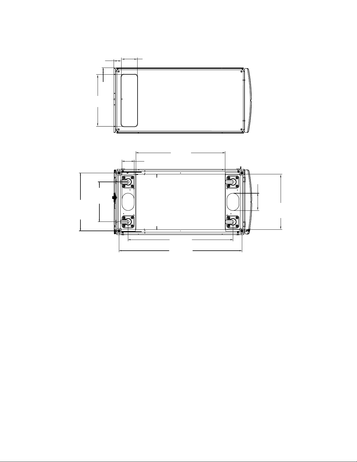
The system cabinet consists of side panels, front and rear doors, an optional bolt-down kit, an
optional interconnect kit, PDUs for your equipment, and an integrated cable management system.
Feature Description
Side panels System cabinets have lockable, removable, and
interchangeable side panels.
Perforated front and rear doors System cabinets have removable front and rear
doors with a quick release mechanism. The
front door is reversible, and the rear doors are
split. Both doors are perforated for cooling.
Common key This key unlocks the front doors, rear doors,
and side panels.
Spares kit This kit is inside the system cabinet, attached to
the cabinet door. It contains the following
components:
• Four 10-32 x 0.75 inch Phillips pilot screws
• Four 10-32 cage nuts
• One cage nut insertion tool
• Two master key copies
Cable access Cable pass-throughs are built into the top and
bottom of the cabinet, as well as between the
bottom of the rear door and the frame.
Cable management Cable management hook and loop strapping is
attached to the frame of the system cabinet at
equal intervals.
Support rails The number of support rails you receive
depends on your configuration. The empty
system cabinet is shipped with no support rails
installed.
• For configured system cabinets, one fixed
rail kit is shipped with the system cabinet to
support the 80xx, FAS8200, and DS4486
rear hold-down brackets.
• Quick-ship system cabinets do not include
the additional fixed rail kit.
4

Feature Description
Blanking panels The number and size of blanking panels you
receive depends on your configuration. The
empty system cabinet is shipped with no
blanking panels installed.
Bolt-down kit This optional kit enables you to secure the
system cabinet to the data center floor. The kit it
is not intended for seismic stability.
• Four bolt-down brackets
• Four spacer brackets
• Six M8x20 mm hex head bolts and washers
Interconnect kit This optional kit enables you to connect
multiple system cabinets to each other.
• Interconnect brackets
◦One set of four interconnect brackets for
connecting the system cabinets with side
panels on
◦One set of four interconnect brackets for
connecting the system cabinets with the
side panels off
• Four M12x20 Torx-30 screws used in
system cabinet with side panels on.
• Eight M6x10 countersunk Torx-30 screws
used in system cabinet with side panels off.
Support rail kit If you ordered additional support rails with your
system cabinet, each kit contains one left and
one right support rail.
Attention: The support rails and kit are
designed to fit only the NetApp 42U 1280
mm system cabinet. Do not use the rails or a
rail kit from other system cabinets because
they are not designed for use in the 42U 1280
mm system cabinet.
• A left and right support rail
• Two screws per rail for securing the rail to
the system cabinet frame
Crescent wrench The crescent wrench is used to remove the hold-
down brackets on the packing pallet, adjust the
system cabinet leveling feet, and install the bolt-
down kit brackets, if ordered.
Preparing to install the system cabinet | 5

Required tools and equipment
Before unpacking and installing on your system cabinet, you should gather the necessary tools and
equipment to move the system cabinet into place and install it or to perform maintenance on it.
• The appropriate hardware guide for your disk shelves
• The appropriate installation and setup instructions for your system
NetApp All Flash FAS Resources
NetApp FAS Storage Systems Resources
NetApp E-Series Systems Documentation Center
• #1 and #2 Phillips screwdrivers
• Torx driver for system cabinet screws
• Leveling tool for leveling the system cabinet
Space requirements and system cabinet dimensions
When unpacking your system cabinet, you must make sure that you have enough room to remove the
system cabinet from the packing material. Also make sure that the intended location for the system
cabinet is large enough for you to move the cabinet into place.
Required space for unpacking the system cabinet
The following table defines the requires space needed to unpack and install your system cabinet:
Dimensions U.S. Metric
Shipping ramp length 80 in. 203.2 cm
Clearance beyond the ramp for
cabinet mobility 72 in. 182.9 cm
Shipping pallet depth 59 in. 149.9 cm
Shipping pallet width 42 in. 106.6 cm
Shipping pallet and packaging
height 86 in. 218.4 cm
Total rack space, 42U 73.5 in. 186.7 cm
Rail load capacity Supports all current systems Supports all current systems
Empty weight ~400 lbs (~181 kg) lbs ~ 181 kg
Fully loaded ship weight Up to 1,800 lbs Up to 816.5 kg
Fully loaded static weight Up to 2,700 lbs Up to 1,224.7 kg
Front service clearance 47.2 in. 120 cm
Rear service clearance
Note: The rear door is split.
Actual minimum rear
clearance is approximately
1/2 the recommendation.
30 in. 76.3 cm
6| 42U 1280 mm System Cabinet Guide

Dimensions U.S. Metric
Minimum side clearance for
panel removal 24 in. 61 cm
Minimum top clearance 12 in. 30 cm
System cabinet exterior dimensions
The following illustration shows the front, rear, and side views of the system cabinet:
FRONT OF CABINET RIGHT SIDE OF CABINET REAR OF CABINET
24.0 in
(60.9 cm)
79.3 in
(201.4 cm)
50.4 in
(128.0 cm)
The following illustrations show top and bottom views of the system cabinet, and identify the
openings through which you can run cable bundles from the floor of your data center into the system
cabinet. The illustrations also show the location of the system cabinet casters and leveling feet.
Caution: To prevent your system cabinet from falling through the data center floor, do not attempt
to roll the system cabinet over a floor opening that is wider than the cable access opening at the
bottom of the system cabinet.
Preparing to install the system cabinet | 7

TOP VIEW OF CABINET
BOTTEM VIEW OF CABINET
(479.88 cm)
Cable Access
(62.75
cm)
(69.7 cm) (148.38 cm)
Cable Access
OPEN
(112 cm)
Cable Access
(824 cm)
Cable Access
(535 cm)
Centerline of
Leveling Feet
(368.5 cm)
Centerline
of Casters
(1135 cm)
Centerline of Leveling Feet
(968 cm)
Centerline of Casters
(160 cm)
Cable
Access
(512 cm)
Cable
Access
REAR FRONT
OPEN
OPEN
OPEN
Supported PDU types and specifications
The system cabinet supports different Power Distribution Unit (PDU) types. The PDUs are compliant
with NEMA or IEC.
The most current information for PDUs supported in your system cabinet is listed in the Hardware
Universe.
hwu.netapp.com
8| 42U 1280 mm System Cabinet Guide

Unpacking the system cabinet
You must remove the packing material that surrounds your system cabinet before you move it into
place. You should also recycle the packing material after the cabinet is unpacked.
1
Remove external bag
and cut straps (x3).
2
x6
Cut
straps
(x2)
Unbuckle the straps
and remove top
outside bumpers.
4
X straps and top bumpers
not used with light load or
empty cabinet shipments.
3
Extra support
bracket not used
with light load or
empty cabinet
shipments.
56
Attach ramp to pallet on side
labeled UNLOAD: align ramp end
bolts with the holes on the pallet
and lower it into place.
x2
front x2
rear x2
7
Remove side
panels
Rear
Front
8
Rear
Remove
cabinet
9
3X
Rear
Front
Move to setup location
9

Installing a system cabinet
You can order a system cabinet with NetApp storage controllers and disk shelves installed in it or an
empty system cabinet if you already have NetApp equipment. Several system cabinets can be
connected together by using the optional interconnect kit, and they can be anchored to the data center
floor by using the optional bolt-down kit.
Installing the cabinet interconnect kit
You can connect system cabinets together by using the optional cabinet interconnect kit. It is
recommended that you install the kit to prevent the cabinets from pulling apart and damaging system
cables.
Steps
1. Place the system cabinets close together.
The cabinets should be arranged similarly to the following illustration, with the cabinet with the
controller modules in the middle, and the cabinets with additional disk shelves on either side. The
sides of the cabinets should be close, but do not need to touch each other yet.
10

System cabinet #3 System cabinet #1 System cabinet #2
2. If you are installing the interconnect kit with the side panels on as recommended, reinstall the
side panels that were removed during unpacking:
a. Lift the side panel, tilting it about 15 degrees away from the system cabinet bottom, and then
hang it over the lip at the top of the system cabinet frame.
b. Gently push the side panel against the cabinet frame, and then lock it in place with the key.
c. Repeat these substeps for the remaining side panels.
3. If you are installing the interconnect kit with the side panels removed, remove the front door
whose hinges are on the edge where the cabinets meet:
a. Unlock and open the front door that is being removed.
b. Use the following illustration for reference to unplug the power to the illuminated bezel:
Installing a system cabinet | 11

Front:
2
Back:
press
1
1
Illuminated bezel circuit board and cable
2
Back panel and thumbscrews
c. Use the following illustration for reference to remove the front door:
12 | 42U 1280 mm System Cabinet Guide

1
2
3
1
Door grounding cable
2
Door top hinge
3
Hinge pin
Make sure that you set the removed doors in a safe place so that they are not accidently damaged.
4. Remove the rear door whose hinges are on the edge where the cabinets meet:
a. Unlock and open the rear door that you are removing.
b. Lift the top hinge pin until it clears the bottom of the hinge.
c. Gently tip the top of the door away from the system cabinet frame, and then release the hinge
pin.
d. Lift the door off the bottom hinge, and then set the door aside.
5. Move the system cabinets completely together, and then align and level them by adjusting the
four leveling feet at the bottom of the system cabinets.
6. Install the interconnect brackets.
• Use the following illustration for reference if you are installing the interconnect brackets with
the system cabinet side panels on, as recommended:
Installing a system cabinet | 13

12 mm
19 mm
Interconnect
bracket
Interconnect
bracket
1
2
1
2
3
1
Plastic push-in rivets on the system cabinet top
2
Top interconnect bracket
3
Bottom interconnect bracket
• Use the following illustration for reference if you are installing the interconnect brackets with
the system cabinet side panels off:
14 | 42U 1280 mm System Cabinet Guide

7. Repeat the process for any remaining system cabinets.
8. Tighten all interconnect bracket screws.
Installing the bolt-down kit
You can secure the system cabinet to the floor by installing the optional bolt-down kit. Installing the
kit prevents the system cabinets from being rolled out of position.
Before you begin
You must supply the appropriate anchor bolt for your floor for each bolt-down bracket.
Steps
1. Mark the area on your floor where the system cabinet will be installed, and then roll the cabinet
into place.
Installing a system cabinet | 15

413 mm
1,257 mm
M8x20 mm
bolts x2
rear
M8x20 mm
bolts x4
front
Secure all 4
brackets to
base with
appropriate
bolts
(not provided)
1
1
2
1
Front and rear bolt-down brackets
2
Location of floor anchor point on the bracket
2. Mark the anchoring points where the rear bolt-down brackets will be anchored to the floor, and
then drill the holes for the brackets.
Be sure to use the appropriate bolt sizes and type for your floor.
3. If the bolt-down brackets are too low to align with the mount points on the system cabinet frame,
place a spacer bracket over the hole in the floor.
4. Loosely bolt the rear brackets to the floor, and then using the kit bolts, bolt the brackets to the
cabinet frame.
5. Mark the anchoring points where the front bolt-down brackets will be anchored to the floor, and
then drill the holes for the brackets.
6. If the bolt-down brackets are too low to align with the mount points on the system cabinet frame,
place a spacer bracket over the hole in the floor.
7. Bolt the front brackets to the floor, and then using the kit bolts, bolt the brackets to the cabinet
frame.
8. Lower the leveling feet as needed, and then tighten the rear bolt-down brackets to the floor.
Installing additional support rails
Your system cabinet has some support rails already installed in it. If you need additional support rails
for your system, you must install them before installing your system components.
About this task
This task applies to all controller and disk shelves except the DS212C and the DE212C disk shelves.
Use the instructions in the rail kit flyer applicable to those two disk shelves.
Installing a DE212C or DS212C Shelf in a Two-Post or Four-Post Rack
16 | 42U 1280 mm System Cabinet Guide

Steps
1. Determine how much space your equipment requires.
Calculate the amount of U space (1.75 inches per U) the equipment requires, based on the
equipment height, and then determine where the equipment will be installed in the system cabinet
based on available space.
2. Locate where you need to install the support rails, and then install them using the following
illustration for reference:
1
2
5
10x32
screw
Use with DS460C only
Use with all other
system chassis
Repeat the steps for
the opposite rail
4
Rear view
Front view
10x32
screw
3
3. If your equipment mounting flanges extend beyond the screw holes in the support rail, install cage
nuts above the support rail, where needed.
Installing a system cabinet | 17

Installing equipment in the system cabinet
After you have installed any additional support rails into the system cabinet, you can add more
system components to your prepopulated system cabinet or add your existing system components to
an empty system cabinet.
Steps
1. Unlock and open the rear doors of the system cabinet and the front door, if it is not already open.
2. Install your equipment into the system cabinet as described in the installation instructions
accompanying your equipment.
The storage controllers should be in the middle of the system cabinet. The disk shelves should be
above and below the storage controllers. Any switches should be at the very top of the system
cabinet.
Note: If your equipment mounting flanges extend beyond the screw holes in the support rail,
install cage nuts above the support rail where needed to secure the equipment to the cabinet
upright.
3. Install blanking panels over any empty bays in the system cabinet.
If you receive the system cabinet with equipment already installed, you must remove the tie-down
rails on top of the equipment that is directly below empty cabinet bays, as shown in the following
illustration:
18 | 42U 1280 mm System Cabinet Guide

7
Blank shipped
on top of unit .
Remove and install.
Rear view
1
5
3
2
6
4
7
7
4. Reinstall the front and rear system cabinet doors.
Powering on the system cabinet
You must connect the system components to the PDUs, route the PDU cables to the AC power
sources, connect them to the power sources, and power on the system.
Before you begin
You must have separate power circuits available for each PDU in your system cabinet.
Steps
1. Connect your equipment to the PDUs, making sure that you connect each component's power
supplies to a PDU on opposite sides of the system cabinet.
2. Feed the PDU power cables through an opening in the system cabinet.
Use one of the following openings:
• The top of the system cabinet
• Between the rear door bottom and frame of the system cabinet
• Through the floor opening and under the system cabinet
3. Turn off the power switches or circuit breakers on the PDUs.
Installing a system cabinet | 19

4. Plug each PDU power cable into individual AC power sources that are on separate AC circuits.
5. Turn on the power switches or circuit breakers to the PDUs.
6. Turn on the power to your components, and then boot the system.
7. Close and lock the system cabinet doors.
20 | 42U 1280 mm System Cabinet Guide
Table of contents
Other NetApp Server manuals