NetApp AFF A150 Instructions for use

Install and setup
Install and maintain
NetApp
June 30, 2023
This PDF was generated from https://docs.netapp.com/us-en/ontap-systems/a150/install-setup.html on
June 30, 2023. Always check docs.netapp.com for the latest.

Table of Contents
Install and setup . . . . . . . . . . . . . . . . . . . . . . . . . . . . . . . . . . . . . . . . . . . . . . . . . . . . . . . . . . . . . . . . . . . . . . . . . . Ê1
Start here: Choose your installation and setup experience . . . . . . . . . . . . . . . . . . . . . . . . . . . . . . . . . . . . . . . Ê1
Quick guide - AFF A150 . . . . . . . . . . . . . . . . . . . . . . . . . . . . . . . . . . . . . . . . . . . . . . . . . . . . . . . . . . . . . . . . . . Ê1
Videos - AFF A150 . . . . . . . . . . . . . . . . . . . . . . . . . . . . . . . . . . . . . . . . . . . . . . . . . . . . . . . . . . . . . . . . . . . . . . Ê1
Detailed guide - AFF A150 . . . . . . . . . . . . . . . . . . . . . . . . . . . . . . . . . . . . . . . . . . . . . . . . . . . . . . . . . . . . . . . . Ê1

Install and setup
Start here: Choose your installation and setup experience
For most configurations, you can choose from different content formats.
•Quick steps
A printable PDF of step-by-step instructions with live links to additional content.
•Video steps
Video step-by-step instructions.
•Detailed steps
Online step-by-step instructions with live links to additional content.
If your system is in a MetroCluster IP configuration, see the Install MetroCluster IP Configuration instructions.
Quick guide - AFF A150
Learn how to install your system from racking and cabling, through initial system bring-up.
Use AFF A150 System Installation and Setup Instructions if you are familiar with installing
NetApp systems.
Videos - AFF A150
Use the following videos to learn how to rack and cable your system and perform initial system configuration.
If you have a MetroCluster configuration, use the MetroCluster documentation.
Hardware installation and cabling The following video shows how to install and cable your system.
Animation - Install and setup of an AFF A150
End-to-end software configuration The following video shows end-to-end software configuration for
systems running ONTAP 9.2 and later.
[] | https://img.youtube.com/vi/WAE0afWhj1c?/maxresdefault.jpg
Detailed guide - AFF A150
This section gives detailed step-by-step instructions for installing an AFF A150 system.
If you have a MetroCluster configuration, use the MetroCluster documentation.
1

Step 1: Prepare for installation
To install your AFF A150 system, you create an account on the NetApp Support Site, register your system, and
obtain your license keys. You also need to inventory the appropriate number and type of cables for your
system and collect specific network information.
Before you begin
•Make sure you have access to NetApp Hardware Universe (HWU) for information about site requirements
as well as additional information on your configured system.
•Make sure you have access to the Release Notes for your version of ONTAP for more information about
this system.
•Contact your network administrator for information about connecting your system to the switches.
•Make sure you have the following items at your site:
◦Rack space for the storage system
◦Phillips #2 screwdriver
◦Additional networking cables to connect your system to your network switch and laptop or console with
a Web browser
◦A laptop or console with an RJ-45 connection and access to a Web browser
Steps
1. Unpack the contents of all boxes.
2. Record the system serial number from the controllers.
3. Set up your account:
a. Log in to your existing account or create an account.
b. Register your system.
4. Download and install Config Advisor on your laptop.
5. Inventory and make a note of the number and types of cables you received.
The following table identifies the types of cables you might receive. If you receive a cable not listed in the
table, see NetApp Hardware Universe to locate the cable and identify its use.
Type of cable… Part number and length Connector type For…
10 GbE cable
(order
dependent)
X6566B-05-R6 (112-00297), 0.5m
X6566B-2-R6 (112-00299), 2m
Cluster interconnect network
10 GbE cable
(order
dependent)
Part number X6566B-2-R6 (112-
00299), 2m
or X6566B-3-R6 (112-00300), 3m
X6566B-5-R6 (112-00301), 5m
Data
2

Type of cable… Part number and length Connector type For…
Optical network
cables (order
dependent)
X6553-R6 (112-00188), 2m
X6536-R6 (112-00090), 5m
X6554-R6(112-00189), 15m
FC host network
Cat 6, RJ-45
(order
dependent)
Part numbers X6585-R6 (112-
00291), 3m
X6562-R6 (112-00196), 5m
Management network and
Ethernet data
Storage (order
dependent)
Part number X66030A (112-
00435), 0.5m
X66031A (112-00436), 1m
X66032A (112-00437), 2m
X66033A (112-00438), 3m
Storage
Micro-USB
console cable
Not applicable Console connection during
software setup on non-Windows
or Mac laptop/console
Power cables Not applicable Powering up the system
6. Download and complete the Cluster Configuration Worksheet.
Step 2: Install the hardware
You install your system in a 4-post rack or NetApp system cabinet, as applicable.
Steps
1. Install the rail kits, as needed.
2. Install and secure your system using the instructions included with the rail kit.
You need to be aware of the safety concerns associated with the weight of the system.
3. Attach cable management devices (as shown).
3

4. Place the bezel on the front of the system.
Step 3: Cable controllers to network
You cable the controllers to your network by using either the two-node switchless cluster method or the
switched cluster method.
About this task
The following table identifies the cable type with the call out number and cable color in the illustrations for both
two-node switchless cluster network cabling and switched cluster network cabling.
Cabling Connection type
Cluster interconnect
Controllers to host data network switches
Controllers to management network switch
4
Option 1: Two-node switchless cluster
Cable your two-node switchless cluster.
About this task
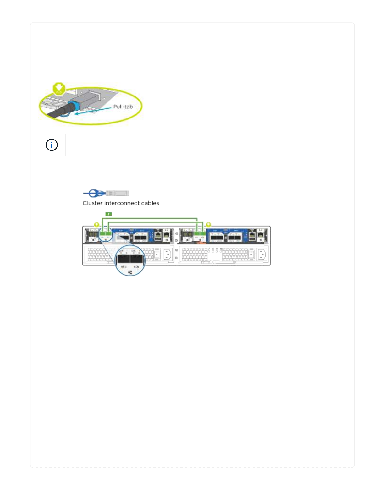
Be sure to check the illustration arrow for the proper cable connector pull-tab orientation.
As you insert the connector, you should feel it click into place; if you do not feel it click,
remove it, turn it around and try again.
Steps
1. Cable the cluster interconnect ports e0a to e0a and e0b to e0b with the cluster interconnect cable.
2. Cable the controllers to either a UTA2 data network or an Ethernet network:
5
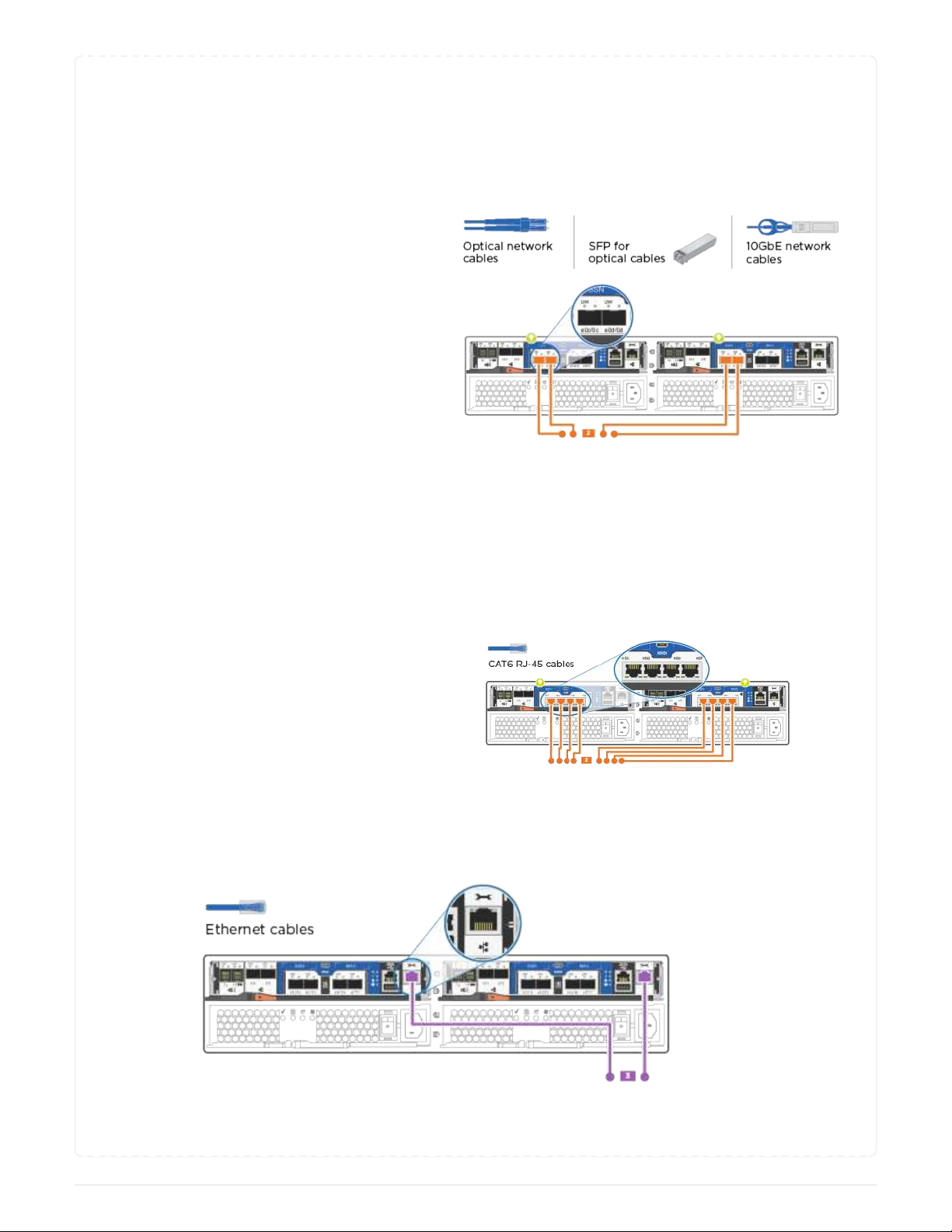
UTA2 data network configurations Use one of the following cable types to cable the UTA2
data ports to your host network.
◦For an FC host, use 0c and 0d or 0e and 0f.
◦For an 10GbE system, use e0c and e0d or e0e and
e0f.
You can connect one port pair as CNA and one port
pair as FC, or you can connect both port pairs as
CNA or both port pairs as FC.
Ethernet network configurations Use the Cat 6 RJ45 cable to cable the e0c through e0f
ports to your host network. in the following illustration.
3. Cable the e0M ports to the management network switches with the RJ45 cables.
6

DO NOT plug in the power cords at this point.
Option 2: Switched cluster
Cable your switched cluster.
About this task
Be sure to check the illustration arrow for the proper cable connector pull-tab orientation.
As you insert the connector, you should feel it click into place; if you do not feel it click,
remove it, turn it around and try again.
Steps
1. For each controller module, cable e0a and e0b to the cluster interconnect switches with the cluster
interconnect cable.
2. You can use either the UTA2 data network ports or the ethernet data network ports to connect the
controllers to your host network:
7

UTA2 data network configurations Use one of the following cable types to cable the UTA2
data ports to your host network.
◦For an FC host, use 0c and 0d or 0e and 0f.
◦For an 10GbE system, use e0c and e0d or e0e and
e0f.
You can connect one port pair as CNA and one port
pair as FC, or you can connect both port pairs as
CNA or both port pairs as FC.
Ethernet network configurations Use the Cat 6 RJ45 cable to cable the e0c through e0f
ports to your host network.
3. Cable the e0M ports to the management network switches with the RJ45 cables.
8
Table of contents
Other NetApp Server manuals


