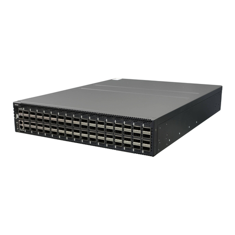
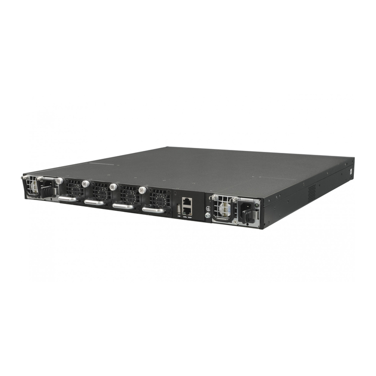
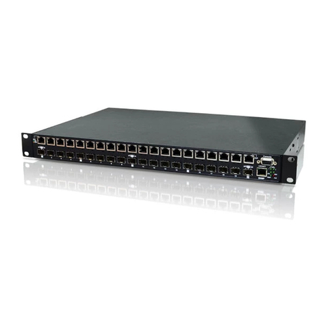
Netberg Aurora 820 User manual

The Aurora 820 switch
installation guide

The Aurora 820 switch installation guide

iii
Table of Contents
1. Introduction ........................................................................................................................ 1
1.1. Intended Application Uses ....................................................................................... 2
2. Hardware Installation .......................................................................................................... 3
2.1. Installation Guidelines .............................................................................................. 4
2.2. Installation into a Rack ............................................................................................ 5
2.3. Rail Kit Installation .................................................................................................. 6
2.3.1. An optional rail kit installation directions. ........................................................ 6
2.3.2. To remove the switch from the rack .............................................................. 8
2.4. Installing Transceivers and Cables into the Switch Ports .......................................... 10
2.4.1. QSFP-DD Port Connection .......................................................................... 10
2.5. Fan Modules ......................................................................................................... 11
2.6. Power supply ........................................................................................................ 13
2.6.1. Replacing a PSU ........................................................................................ 13
2.7. Connect the Power Cable ...................................................................................... 15
2.8. Grounding the Switch ............................................................................................ 16
2.9. Rack-mount Safety Precautions ............................................................................. 17
2.10. The Warranty VOID Label .................................................................................... 18
2.11. Console port ........................................................................................................ 19
3. Netberg Aurora 820 switch ............................................................................................... 20
3.1. Button and System LED Information ....................................................................... 22
3.2. Specification .......................................................................................................... 26
3.3. Supported Cables and Transceivers ....................................................................... 27

iv
List of Figures
2.1. Front ears installation ...................................................................................................... 5
2.2. Detaching the Inner Rail .................................................................................................. 6
2.3. Attaching Inner Rail to the Switch .................................................................................... 6
2.4. Attaching Outer Rail on the Rear to the Rack ................................................................... 7
2.5. Attaching Outer Rail on the Front to the Rack .................................................................. 7
2.6. Pushing Switch into the Rack .......................................................................................... 8
2.7. Installing Switch into the Rack ......................................................................................... 8
2.8. Removing Switch from the Rack ...................................................................................... 9
2.9. Transceivers and cables ................................................................................................ 10
2.10. Fan modules location .................................................................................................. 11
2.11. Removing the fan module ............................................................................................ 11
2.12. Inserting the fan module .............................................................................................. 12
2.13. PSU modules location ................................................................................................. 13
2.14. Removing the PSU module .......................................................................................... 14
2.15. Inserting the PSU module ............................................................................................ 14
3.1. Aurora 820 front view .................................................................................................... 20
3.2. Port numbering ............................................................................................................. 20
3.3. Aurora 820 rear view ..................................................................................................... 20
3.4. Front Panel Button and LED .......................................................................................... 22
3.5. Rear Panel LED ............................................................................................................ 22

v
List of Tables
2.1. Serial port pin definition ................................................................................................. 19
3.1. Front panel features ...................................................................................................... 20
3.2. Rear panel features ....................................................................................................... 21
3.3. Front panel features ...................................................................................................... 22
3.4. Rear panel features ....................................................................................................... 22
3.5. LED definition ............................................................................................................... 23
3.6. Optics and Cables Support ............................................................................................ 27

1
Chapter 1. Introduction
This guide is to assist the reader with the most basic form of installation and cable connection to
our switches. As there is more than one switch in the Aurora series, the actual port placement
might slightly differ, however, the installation and connection logic are the same for all Netberg
switches.
Package Contents:
• One Netberg Aurora Switch
• Two AC power cords.
• One console cable.
• One pair of frontal rack-mount ears.
If any of the above mention items was not found inside the package contents of this
switch or are damaged in any way, contact your reseller immediately.

Introduction
2
1.1. Intended Application Uses
This product was evaluated as Information Technology Equipment (ITE), which may be installed in
offices, schools, computer rooms, and similar commercial type locations. Other than an ITE appli-
cation, this product’s suitability for different product categories and environments (such as medical,
industrial, residential, alarm systems, and test equipment) may require further evaluation.

3
Chapter 2. Hardware Installation

Hardware Installation
4
2.1. Installation Guidelines
This section will discuss the hardware installation guidelines that administrators must follow in or-
der to properly and safely install this switch into the appropriate environment.

Hardware Installation
5
2.2. Installation into a Rack
The switch can be secured in a standard 19"(1U) rack using the provided mounting ears. The fol-
lowing section will explain how to install the rack-mount ears onto the switch and then mount the
switch into a standard 1U rack-mount unit.
1. Use the supplied screws to attach a mounting ear to each side of the Switch.
2. Align the holes in the mounting ear with the holes in the rack.
3. Insert and tighten screws through each of the mounting ears.
Figure2.1.Front ears installation
Two individuals are recommended to install the switch. One individual should position
the switch in the rack, while the other secures it using the rack screws.
Illustrations are for reference purposes only. Actual cabinet posts may differ.

Hardware Installation
6
2.3. Rail Kit Installation
2.3.1. An optional rail kit installation directions.
1. Push the tab in the direction as indicated to detach the inner rail from the slide.
Figure2.2.Detaching the Inner Rail
2. Align the inner rail to the retaining posts on the side of the switch.
3. Push the inner rail in the direction as indicated until it clicks into place with the retaining posts.
Figure2.3.Attaching Inner Rail to the Switch
4. Press the retaining clip on the rear end as indicated.
5. Attach the outer rail to the rack on the rear end, and lock it by releasing the clip till it clicks into
place with rack.

Hardware Installation
7
Figure2.4.Attaching Outer Rail on the Rear to the Rack
6. Press the retaining clip on the front end as indicated.
7. Attach the outer rail to the rack on the front end, and lock it by releasing the clip till it clicks into
place with rack.
Figure2.5.Attaching Outer Rail on the Front to the Rack
8. Completed the rail installation on both sides. Align the rail and push the switch into the rack.

Hardware Installation
8
Figure2.6.Pushing Switch into the Rack
9. Tighten screws on both sides to lock switch on the rack.
Figure2.7.Installing Switch into the Rack
2.3.2. To remove the switch from the rack
1. Push the tabs on both sides of the inner rails in the direction as indicated.
2. Remove the switch out of the rack.

Hardware Installation
9
Figure2.8.Removing Switch from the Rack

Hardware Installation
10
2.4. Installing Transceivers and Cables into
the Switch Ports
Figure2.9.Transceivers and cables
27
28
29
30
31
32
2.4.1. QSFP-DD Port Connection
QSFP-DD ports which support 400G/per port or fan out to 4x100G by using the fan-out DAC cable.
1. Slide the QSFP-DD module into a QSFP-DD port.
Ensure the QSFP-DD module is positioned correctly before installing it into the port.
2. Push completely until the module locks into place.
3. Repeat the above procedures to install additional QSFP modules.
The QSFP-DD port LED lights green when the network link is established.

Hardware Installation
11
2.5. Fan Modules
This product contains six system fan modules which are located at the rear of the chassis.
The location of the system fan modules is shown below:
Figure2.10.Fan modules location
The fan module is a field replaceable unit and can be replaced during operations as long as the re-
maining modules are installed and operating.
Replacing fan modules
1. Press the retaining tab on the system fan module in the direction as indicated.
2. Remove the system fan module out of the chassis.
Figure2.11.Removing the fan module
3. Push the system fan module into the system fan module bay until it connects properly with the
fan board in the chassis.

Hardware Installation
12
Figure2.12.Inserting the fan module

Hardware Installation
13
2.6. Power supply
Equipped with two supply modules, the switch can operate with either one or two power supply
modules. If the switch uses two power supply modules, you can hot-swap one of the PSU during
the operations. Even if one of the two power supplies has failed, or is not in use, do not pull out
the power supply from the chassis. This is to prevent hot air being suck back into the chassis from
the empty power supply shelf when the system is in operation. Only pull out the bad power supply
when the replacement is ready to be installed.
This product is designed with two 1300W power supplies.
Figure2.13.PSU modules location
The location of power supplies on the product is shown below:
One PSU is enough for a fully loaded chassis.
2.6.1. Replacing a PSU
1. Hold the PSU handle and press the release latch to unlock from the switch.
2. Pull the PSU module out of the switch.

Hardware Installation
14
Figure2.14.Removing the PSU module
3. Align the PSU with the switch bay.
4. Slide the PSU into the switch and push until it is flush with the bay. The retaining clip should
snap.
Figure2.15.Inserting the PSU module
The AC power connector is a standard three-pronged connector. The switch automatically adjusts
its power setting to any supply voltage in the range from 100-240 VAC at 50-60 Hz.

Hardware Installation
15
2.7. Connect the Power Cable
Connect one end of the AC power cord, included in the package, into the grounded electrical outlet
at the site and insert the other end of the AC power cord into the AC power receptacle of the AC
power supply module on the back panel of the switch. The switch will automatically adjust the volt-
age supplied to the voltage needed as this power supply supports any voltage power supply in the
range from 100VAC to 240VAC at 50Hz to 60Hz.
The LED indicators on the front panel of the switch should lights green after power-on.
Table of contents
Other Netberg Switch manuals
