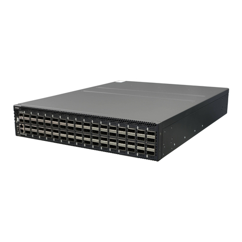
Netberg Aurora 615 User manual

The Aurora 615 switch
installation guide

The Aurora 615 switch installation guide

iii
Table of Contents
1. Introduction ........................................................................................................................ 1
2. Hardware Installation .......................................................................................................... 2
2.1. Installation Guidelines .............................................................................................. 3
2.2. Installation into a Rack ............................................................................................ 4
2.3. Installing Transceivers and Cables into the Switch Ports ........................................... 5
2.3.1. SFP+/SFP28 Port Connection (LC Type Connector) ....................................... 5
2.3.2. QSFP+/QSFP28 Port Connection .................................................................. 6
2.4. Fan Modules ........................................................................................................... 7
2.5. Power supply .......................................................................................................... 8
2.5.1. Replacing a PSU .......................................................................................... 8
2.6. Connect the Power Cable ...................................................................................... 10
2.7. Grounding the Switch ............................................................................................ 11
2.8. Rack-mount Safety Precautions ............................................................................. 12
2.9. Console port ......................................................................................................... 13
3. Netberg Aurora 615 switch ............................................................................................... 14
3.1. Button and System LED Information ....................................................................... 16
3.2. Specification .......................................................................................................... 19
3.3. Supported Cables and Transceivers ....................................................................... 21

iv
List of Figures
2.1. Front ears installation ...................................................................................................... 4
2.2. Transceivers and cables .................................................................................................. 5
2.3. Removing the fan module ................................................................................................ 7
2.4. Inserting the fan module .................................................................................................. 7
2.5. Removing the PSU module ............................................................................................. 8
2.6. Inserting the PSU module ................................................................................................ 9
3.1. Aurora 615 front view .................................................................................................... 14
3.2. Aurora 615 rear view ..................................................................................................... 14
3.3. Aurora 615 side view ..................................................................................................... 15
3.4. Front Panel Button and LED .......................................................................................... 16
3.5. Rear Panel Button and LED .......................................................................................... 18

v
List of Tables
2.1. Console cable pin definition ........................................................................................... 13
3.1. Front panel features ...................................................................................................... 14
3.2. Rear panel features ....................................................................................................... 14
3.3. Side panel features ....................................................................................................... 15
3.4. Front panel features ...................................................................................................... 16
3.5. System LED Indicator definitions .................................................................................... 16
3.6. QSFP28 Per-Port Four LEDs Configuration definitions .................................................... 17
3.7. Ports Activity LED Information ........................................................................................ 17
3.8. Rear panel features ....................................................................................................... 18
3.9. Back View LEDs ........................................................................................................... 18

1
Chapter 1. Introduction
This guide is to assist the reader with the most basic form of installation and cable connection to
our switches. As there is more than one switch in the Aurora series, the actual port placement
might slightly differ, however, the installation and connection logic are the same for all Netberg
switches.
Package Contents:
• One Netberg Aurora Switch
• Two AC power cords.
• One console cable.
• One pair of frontal rack-mount ears.
If any of the above mention items was not found inside the package contents of this
switch or are damaged in any way, contact your reseller immediately.

2
Chapter 2. Hardware Installation

Hardware Installation
3
2.1. Installation Guidelines
This section will discuss the hardware installation guidelines that administrators must follow in or-
der to properly and safely install this switch into the appropriate environment.

Hardware Installation
4
2.2. Installation into a Rack
The switch can be secured in a standard 19"(1U) rack using the provided mounting ears. The fol-
lowing section will explain how to install the rack-mount ears onto the switch and then mount the
switch into a standard 1U rack-mount unit.
1. Use the supplied screws to attach a mounting ear to each side of the Switch.
2. Align the holes in the mounting ear with the holes in the rack.
3. Insert and tighten screws through each of the mounting ears.
Figure2.1.Front ears installation
Two individuals are recommended to install the switch. One individual should position
the switch in the rack, while the other secures it using the rack screws.
Illustrations are for reference purposes only. Actual cabinet posts may differ.

Hardware Installation
5
2.3. Installing Transceivers and Cables into
the Switch Ports
Figure2.2.Transceivers and cables
27
28
29
30
31
32
2.3.1. SFP+/SFP28 Port Connection (LC Type Connec-
tor)
The Small Form-Factor Pluggable Plus (SFP+) port is the second generation of the SFP intercon-
nect system designed for 10Gb/s data rate. The SFP+ ports support 10-gigabit IEEE 802.3ae Eth-
ernet for fiber mediums.
The Small Form-Factor Pluggable 28 (SFP28) port is the next generation of the SFP interconnect
system designed for 25Gb/s data rate. The SFP28 ports enables error-free transmission of 25 Gb/
s over 100 meters of OM4 multimode fiber.
The SFP+/SFP28 ports are numbered and have corresponding SFP port LEDs.
To install an SFP module, do the following:
1. Slide the SFP module into an SFP port.
Ensure the SFP module is positioned correctly before installing it into the port.
2. Push completely until the module locks into place.
3. Repeat the above procedures to install additional SFP+ modules.
The SFP port LED lights green when the network link is established.

Hardware Installation
6
2.3.2. QSFP+/QSFP28 Port Connection
QSFP+ (Quad SFP) ports which support 40G/per port or fan out to 4x10G by using the fan out
DAC cable.
QSFP28 (Quad SFP) ports which support 100G/per port or fan out to 4x25G by using the fan out
DAC cable.
1. Slide the QSFP module into a QSFP port.
Ensure the QSFP module is positioned correctly before installing it into the port.
2. Push completely until the module locks into place.
3. Repeat the above procedures to install additional QSFP modules.
The QSFP port LED lights green when the network link is established.

Hardware Installation
7
2.4. Fan Modules
The fan module is a field replaceable unit and can be replaced during operations as long as the re-
maining modules are installed and operating.
Replacing fan modules
1. Press the retaining tab on the system fan module in the direction as indicated.
2. Remove the system fan module out of the chassis.
Figure2.3.Removing the fan module
3. Push the system fan module into the system fan module bay until it connects properly with the
fan board in the chassis.
Figure2.4.Inserting the fan module

Hardware Installation
8
2.5. Power supply
Equipped with two supply modules, the switch can operate with either one or two power supply
modules. If the switch uses two power supply modules, you can hot-swap one of the PSU during
the operations. Even if one of the two power supplies has failed, or is not in use, do not pull out
the power supply from the chassis. This is to prevent hot air being suck back into the chassis from
the empty power supply shelf when the system is in operation. Only pull out the bad power supply
when the replacement is ready to be installed.
One PSU is enough for a fully loaded chassis.
2.5.1. Replacing a PSU
1. Hold the PSU handle and press the release latch to unlock from the switch.
2. Pull the PSU module out of the switch.
Figure2.5.Removing the PSU module
3. Align the PSU with the switch bay.
4. Slide the PSU into the switch and push until it is flush with the bay. The retaining clip should
snap.

Hardware Installation
9
Figure2.6.Inserting the PSU module
The AC power connector is a standard three-pronged connector. The switch automatically adjusts
its power setting to any supply voltage in the range from 100-240 VAC at 50-60 Hz.

Hardware Installation
10
2.6. Connect the Power Cable
Connect one end of the AC power cord, included in the package, into the grounded electrical outlet
at the site and insert the other end of the AC power cord into the AC power receptacle of the AC
power supply module on the back panel of the switch. The switch will automatically adjust the volt-
age supplied to the voltage needed as this power supply supports any voltage power supply in the
range from 100VAC to 240VAC at 50Hz to 60Hz.
The LED indicators on the front panel of the switch should lights green after power-on.

Hardware Installation
11
2.7. Grounding the Switch
It is recommended that a compliant system is installed as part of the chassis to reduce or prevent
the risk of shock hazards, greatly reduce the risk of equipment damage or reduce the potential of
data corruption.
This equipment must be grounded. Do not defeat the ground conductor or operate the
equipment without a suitably installed ground conductor. Contact the appropriate elec-
trical inspection authority or an electrician if you are uncertain that suitable grounding
is available.
1. Ensure the rack is properly grounded and in compliance with local regulatory guidelines. Ensure
that a good electrical connection to the grounding point exists. Remove any paint or material
that may prevent good contact.
2. This product is equipped with a three-wire power cable and plug for user safety. Use the power
cable with a properly grounded electrical outlet to avoid electric shock.

Hardware Installation
12
2.8. Rack-mount Safety Precautions
For your protection, observe the following rack-mount safety precautions when setting up your
equipment:
• Elevated Operating Ambient - If installed in a closed or multi-unit rack assembly, the operating
ambient temperature of the rack environment may be greater than room ambient. Therefore,
consideration should be given to installing the equipment in an environment compatible with the
maximum ambient temperature (Tma) specified by the manufacturer.
• Reduced Air Flow - Installation of the equipment in a rack should be such that the amount of air
flow required for safe operation of the equipment is not compromised.
• Mechanical Loading - Mounting of the equipment in the rack should be such that a hazardous
condition is not achieved due to uneven mechanical loading.
• Circuit Overloading - Consideration should be given to the connection of the equipment to the
supply circuit and the effect that overloading of the circuits might have on overcurrent protection
and supply wiring. Appropriate consideration of equipment nameplate ratings should be used
when addressing this concern.
• Reliable Earthing - Reliable earthing of rack-mounted equipment should be maintained. Partic-
ular attention should be given to supply connections other than direct connections to the branch
circuit (for example, use of power strips).
• For safety, equipment should always be loaded from the bottom up. That is, install the equip-
ment that will be mounted in the lowest part of the rack first, then the next higher systems, etc.
• To prevent the rack from tipping during equipment installation, the anti-tilt bar on the rack must
be deployed.
• The mounting brackets provided must be used to securely mount the device in a rack-mount
unit.

Hardware Installation
13
2.9. Console port
The console port is used for setting up and managing the switch via a connection to a console ter-
minal or PC using a terminal emulation program. You can connect the switch to a terminal or PC
using the supplied console cable (RJ-45 male to RS-232 female cable) for serial communication.
Below is the console cable wiring specification table:
Table2.1.Console cable pin definition
RJ-45 Port of Switch DB9 Female Port of
PC
Abbreviation Description
3 2 RD Received Data
6 3 TD Transmit Data
1 8 CTS Clear To Send
8 7 RTS Request To Send
Using the console port, you can perform the following:
• Configure, manage and monitor the switch using the CLI commands
• Manage and monitor network activity by Simple Network Management Protocol (SNMP) man-
agement
• Upgrade the firmware
To connect to the console, do the following:
1. Connect the RJ-45 connector to the console port (|o|o ) of the switch.
2. Connect the RS-232 end to a terminal or PC.
3. Manage the switch using the CLI commands (refer to the CLI User Manual for more informa-
tion).
The switch uses the following default settings:
• Baud rate: 115200
• Data width: 8 bits
• Parity: None
• Stop bits: 1
• Flow control: None

14
Chapter 3. Netberg Aurora 615 switch
The switch chassis is equipped with the following ports:
• 48x 25G SFP28 + 8x 100G QSFP28 ports supporting an optical transceiver, active optical ca-
bles, or direct-attached cable to connect the QSFP28 port to the hosts (uplink connections)
• 1 Management ports enables you to manage the switch operation using an RJ-45 Ethernet ca-
ble
• 1 Console port to perform the initial configuration by connecting to a PC with the RJ-45 to DB-9
serial adapter cable
• 1 USB port to load the configuration files or OS from a USB storage device to the switch’s flash/
SSD memory
Figure3.1.Aurora 615 front view
Table3.1.Front panel features
No Description
1 LED indicators
2 48x 25G SFP28 Ports
3 8x 100G QSFP28 Ports
Figure3.2.Aurora 615 rear view
Table3.2.Rear panel features
No Description
1 AC Power Socket 2
2 AC Power Socket 1
3 Management Port
4 USB Port
5 Console Port

Netberg Aurora 615 switch
15
No Description
6 4x system fans
Figure3.3.Aurora 615 side view
Table3.3.Side panel features
No Description
1 Mounting holes
Table of contents
Other Netberg Switch manuals
Popular Switch manuals by other brands

IN-COMMAND
IN-COMMAND NCSTS9 Installation and operation manual
Hama
Hama Data Switch Operating instruction
TRENDnet
TRENDnet TO-PG541 Quick installation guide
Binary
Binary B-260-SWTCH-4X1 Nstallation guide
Matrix Switch Corporation
Matrix Switch Corporation MSC-HD81DES product manual
Gefen
Gefen EXT-DVI-422DL user manual
Perle
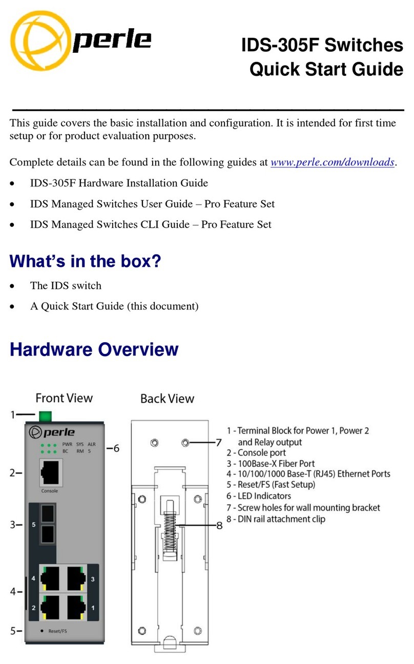
Perle IDS-305F quick start guide
My-Serenity
My-Serenity Smart Plug user guide
Generac Power Systems
Generac Power Systems RXGW20SHA3 owner's manual
Raritan
Raritan PARAGON II Series user guide

Kramer
Kramer VP-553 user manual
Enterasys
Enterasys Vertical Horizon VHIM100-S2MFX 100BASE FX-SC Quick installation guide
