NetComm Wireless NP731 User manual

User Guide
NP731 –Outdoor Dual Band WiFi N Access Point

2
NP731 User Guide
www.netcommwireless.com
Ver 1.1
Copyright
Copyright© 2017 NetComm Wireless Limited. All rights reserved.
The information contained herein is proprietary to NetComm Wireless. No part of this document may be translated, transcribed,
reproduced, in any form, or by any means without prior written consent of NetComm Wireless.
Note: This document is subject to change without notice.
Save our environment
When this equipment has reached the end of its useful life, it must be taken to a recycling centre and processed separately from
domestic waste.
The cardboard box, the plastic contained in the packaging, and the parts that make up this device can be recycled in accordance
with regionally established regulations. Never dispose of this electronic equipment along with your household waste. You may be
subject to penalties or sanctions under the law. Instead, ask for disposal instructions from your municipal government.
Please be responsible and protect our environment.
This manual covers the following products:
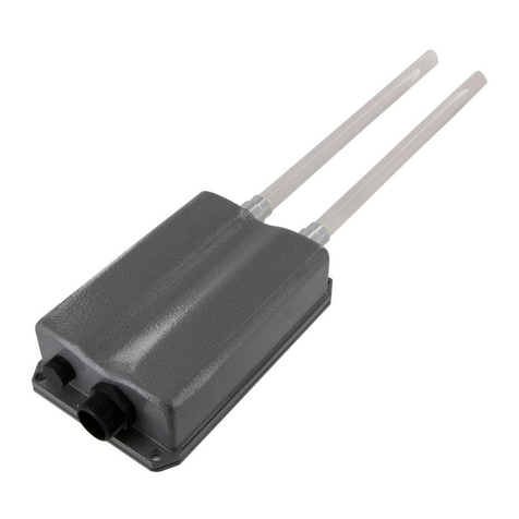
NP731 Outdoor Dual Band WiFi N Access Point
DOCUMENT VERSION
DATE
1.0 - Initial document release
9 January 2015
1.1 –Correction to WDS mode description
12 October 2017
Table 1 - Document Revision History

www.netcommwireless.com
3
NP731 User Guide
Ver 1.1
Table of contents
Table of contents...........................................................................................................................................................................3
Overview ........................................................................................................................................................................................4
Introduction...................................................................................................................................................................................................4
Target audience.............................................................................................................................................................................................4
Prerequisites .................................................................................................................................................................................................4
Notation ........................................................................................................................................................................................................4
Product introduction......................................................................................................................................................................5
Product overview........................................................................................................................................................................................... 5
Package contents..........................................................................................................................................................................................5
System concept ............................................................................................................................................................................................6
Hardware overview ........................................................................................................................................................................7
Bottom Panel ................................................................................................................................................................................................7
Top Panel......................................................................................................................................................................................................8
Hardware Installation.....................................................................................................................................................................9
Alternative configuration...............................................................................................................................................................................10
Accessing the NP731’s user interface ........................................................................................................................................11
Setting the IP address of your computer....................................................................................................................................................... 11
Logging in to the NP731 .............................................................................................................................................................................. 13
Advanced configuration ..............................................................................................................................................................14
System........................................................................................................................................................................................................ 14
AP...............................................................................................................................................................................................................20
Firewall........................................................................................................................................................................................................ 36
Utilities ........................................................................................................................................................................................................42
Status .........................................................................................................................................................................................................46

4
NP731 User Guide
www.netcommwireless.com
Ver 1.1
Overview
Introduction
This document provides you all the information you need to set up, configure and use the Outdoor Dual Band WiFi N Access Point.
Target audience
This guide is intended to be used by wireless service providers or network administrators to set up a network environment using the
NP731 system. It contains step-by-step procedures and graphic examples to guide IT staff or individuals with some network system
knowledge to complete the installation.
Prerequisites
Before continuing with the installation of your NP731, please confirm that you have the following:
A device with a working Ethernet network adapter.
Wireless client device(s) if using the NP731 to create a wireless network.
A web browser such as Internet Explorer, Mozilla Firefox or Google Chrome.
Notation
The following symbols are used in this user guide:
The following note requires attention.
The following note provides a warning.
The following note provides useful information.

www.netcommwireless.com
5
NP731 User Guide
Ver 1.1
Product introduction
Product overview
Designed to meet the needs of today’s most demanding wireless LAN deployments, the NP731 offers a solution to create a reliable
and scalable wireless network.
The NP731 is an outdoor device that will operate in access point, repeater and WDS bridge mode. Its rugged IP68-rated metal
housing is weatherproof, pressure balancing, water-tight and rust-resistant, making it an ideal solution for deployments in harsh
conditions, such as outdoor or industrial environments.
With its multi-mode set up, the device can be used in many instances to increase and enhance wireless coverage.
Package contents
The NP731 package includes:
#
ITEM
DESCRIPTION
1
NetComm Wireless NP731 Outdoor Dual Band WiFi N Access Point
2
Dual band 5dBi Outdoor Omni Antennas
3
Ground wire (green)
4
PoE injector
5
10m RJ45 Outdoor-grade Ethernet cable
6
Detachment tool (for RJ45 connector)
7
Mounting kit
8
Quick Start Guide
9
Not pictured
Warranty Card
If any of these items are missing or damaged, please contact NetComm Wireless Support immediately. The NetComm Wireless
Support website can be found at: http://support.netcommwireless.com.
We recommend that you keep the original packaging materials in case repair or maintenance is necessary. This will protect the
NP731 from damage during transport.

6
NP731 User Guide
www.netcommwireless.com
Ver 1.1
System concept
The NP731 has four modes of operation:
1. Repeater mode (default) –the NP731 repeats the wireless signal of your existing network to provide coverage to a greater
area of your premises.
Note: The NP731 can only rebroadcast the wireless network using the same band, i.e if the router is broadcasting on
2.4GHz, the NP731 can only repeat the signal on 2.4GHz. Additionally, if the router broadcasts on both 2.4GHz and 5GHz
simultaneously, the repeater may only repeat one of those bands.
2. Access Point mode –the NP731 connects to an existing router via Ethernet and provides a wireless signal for wireless
devices. This is useful in situations where there is no existing wireless access point or where you wish to provide a wireless
signal to a remote area (up to 100 metres) from where the router is located.
Note: The NP731 provides wireless connectivity on the 2.4GHz or 5GHz band but not on both bands simultaneously.
3. CPE mode –the NP731 connects wirelessly to a remote network and provides access to that network to clients
connected via Ethernet. Use of a switch is required for multiple clients.
4. WDS mode –the NP731 connects to up to 8 other NP731 units to create a wireless mesh network. This is similar to
repeater mode but in WDS mode, the NP731 uses a single MAC address to provide seamless roaming.

www.netcommwireless.com
7
NP731 User Guide
Ver 1.1
Hardware overview
Bottom Panel
#
NAME
DESCRIPTION
1
Ventilation Valve
Due to fluctuations in temperature and humidity, water vapour inside the unit may condense. This valve
provides ventilation to prevent moisture from building up inside the unit.
2
Ground connector
Used to attach the ground wire.
3
PoE connector
Used to connect the NP731 to either the PoE injector or to a router providing Power over Ethernet (PoE).
1
2
3

8
NP731 User Guide
www.netcommwireless.com
Ver 1.1
Top Panel
#
NAME
DESCRIPTION
1
N-type connectors
Connect antennas here. Use both antennas in conjunction for 802.11n MIMO optimized
performance.
1
1

www.netcommwireless.com
9
NP731 User Guide
Ver 1.1
Hardware Installation
The following diagram illustrates the basic network topology that should be used for testing and configuration:
1. Connect the two Dual band antennas to the primary and secondary N-type antenna connectors on the NP731
2. Unscrew the weather seal from the PoE port and disassemble it so that it is in three parts.
3. Place the Ethernet cable through the bottom piece (A) first, as shown below.

10
NP731 User Guide
www.netcommwireless.com
Ver 1.1
4. Open the middle piece (B) and slide the Ethernet cable into it. Take care to orient the middle piece as shown below.
5. Place the third piece (C) over the top with the same orientation as shown below.
6. Connect the weather sealed end of the Ethernet cable to the Ethernet port of the NP731. Screw part A onto the Ethernet
port of the NP731. Connect the other end of the Ethernet cable to the P+D/OUT port of the PoE injector.
7. Connect one end of another Ethernet cable to the DATA/IN port of the PoE injector and the other end of the cable to a
computer.
8. Connect the power cord to the PoE injector and power it on.
Alternative configuration
When you have completed the configuration of the NP731, you can connect it to a PoE switch to provide power and data
connectivity. The following diagram illustrates the alternative network topology.

www.netcommwireless.com
11
NP731 User Guide
Ver 1.1
Accessing the NP731’s user
interface
The NP731 offers a web based configuration page. After completing the hardware installation above, the NP731 can be configured
through a computer using a web browser with JavaScript enabled.
The NP731 has a static IP address of 192.168.1.254. To access the web management interface, you must set the IP address of
your computer to be within the range of 192.168.1.2 to 192.168.1.253.
Setting the IP address of your computer
To set the IP address of your computer:
1. Open the Control Panel then select Network and Sharing Center.
2. Select the Ethernet connection for the Unidentified network.
3. Click on the Properties button.

12
NP731 User Guide
www.netcommwireless.com
Ver 1.1
4. Select Internet Protocol Version 4 (TCP/IPv4) and then click on the Properties button.
5. Select the Use the following IP address option, then enter an IP address between the range of 192.168.1.2 and
192.168.1.253. In the Subnet mask field, enter 255.255.255.0. Click the OK button.
6. Close the Ethernet Properties and Ethernet Status windows.

www.netcommwireless.com
13
NP731 User Guide
Ver 1.1
Logging in to the NP731
To access the NP731’s user interface:
1. Open a web browser and enter http://192.168.1.254 into the address bar. Press Enter. The login page of the NP731 is
displayed.
2. Enter admin into both the Username and Password fields, then click the Login button

14
NP731 User Guide
www.netcommwireless.com
Ver 1.1
Advanced configuration
The device’s interface consists of 5 main menu items listed along the top of the screen; System, AP, Firewall, Utilities and Status.
You can select any of these menu items to reveal additional sub-menus.
System
The System menu provides the configuration of network related settings.
General
The General tab includes configuration options for System Information to identify the access point as well as NTP server
configuration. The fields marked with a red asterisk are mandatory fields and must contain some data in order for the access point
to function correctly.
FIELD
DESCRIPTION
System Information
Name
This is a name to identify the access point on the network and is a mandatory field.
Description
An optional field used to describe the access point. This is useful for identification purposes where multiple access points are
being used.
Location
An optional field that describes the location of the access point. This is useful for identification purposes where multiple access
points are being used.
Time
Device Time
Displays the time on the device.
Time Zone
Used to select the time zone in which the device is located.
Time
Selects whether the access point should retrieve the time from a time server or use a manually specified time.
NTP Server 1
A mandatory field if NTP is enabled. You must specify at least one NTP server for the access point to synchronize its time.
NTP Server 2
An optional secondary time server address.

www.netcommwireless.com
15
NP731 User Guide
Ver 1.1
Operating Mode
The Operating Mode tab allows you to select between Access Point or CPE mode. To change the mode of operation, select the
desired option and then click the Save button. Click the OK button on the pop-up confirmation window to reboot the access point
so that the change can take effect. When set to CPE mode, the NP731 becomes a DHCP server operating on the 192.168.20.X
address range and retrieves a DHCP client address for the WAN interface.
Network Interface
The Network Interface tab provides you with the ability to configure network settings.

16
NP731 User Guide
www.netcommwireless.com
Ver 1.1
FIELD
DESCRIPTION
Network Settings
Mode
Specifies whether the access point should use a Static IP or a DHCP address. When Static is selected, you must specify
an IP address, Netmask, Default Gateway and Primary DNS Server.
Ethernet IGMP Snooping
Enables or disables the IGMP Snooping function. When enabled, the access point forwards IGMP traffic transferred via
the access point’s network interface and the IP multicast host. Registration information is recorded and sorted into
multicast groups. The internal switch forwards traffic only to those ports that request multicast traffic. Adversely, without
IGMP snooping, multicast traffic is treated like broadcast traffic, with packets forwarded to all ports causing network
inefficiencies.
Layer2 STP
Enables or disables the Layer2 Spanning Tree Protocol. If the access point is set up to bridge other network
components, this option can be enabled to prevent undesired loops because a broadcasting storm may occur in a multi-
switch environment where broadcast packets are forwarded in an endless loop between switches. Enabling Layer2 STP
can lower undesired occurrences of broadcast storms.
Management
Management services such as VLAN, SNMP and the System log may be configured via this page.
FIELD
DESCRIPTION
Management Services
VLAN for Management
When this is enabled, management traffic from the system is tagged with a VLAN ID. To access the VLAN, traffic must
be tagged with the same VLAN ID.
SNMP Configuration
When SNMP is enabled, an administrator can obtain system information and configure settings of the access point
remotely.
System Log
When enabled, the access point can log system activity to a remote syslog server.
Management IP List
Select this option to edit the Management IP list.

www.netcommwireless.com
17
NP731 User Guide
Ver 1.1
SNMP Account List
The System allow 5 SNMP users with Read or Read & Write access. Use the SNMP Account List page to configure access rights.
Management IP List
The administrator can grant access to the web management interface by specifying a list of IP addresses or ranges of IP addresses.
These addresses may be LAN or WAN addresses. Use this page to configure the IP addresses that are allowed access.

18
NP731 User Guide
www.netcommwireless.com
Ver 1.1
CAPWAP
CAPWAP is a standard interoperable protocol that enables a controller to manage a collection of wireless access points. There are
5 methods of auto AP discovery, namely DNS SRV, DHCP option, Broadcast, Multicast and Static.
FIELD
DESCRIPTION
CAPWAP Configuration
CAPWAP
Enables or disables the CAPWAP function.
Certificate Date Check
To enable this, select the Enable option then click the Manage Certificates button to display the Upload Certificate page.
See below for details.
DNS SRV Discovery
Enables or disables the DNS SRV Discovery method.
DHCP Option Discovery
Enables or disables the DHCP Option Discovery method.
Broadcast Discovery
Enables or disables the Broadcast Discovery method.
Multicast Discovery
Enables or disables the Multicast Discovery method.
Static Discovery
Enables or disables the Static Discovery method.
AC Address
The IP address of the access controller. The access point attempts to discover the controllers from the top down, so if
the first address is not reachable, it will attempt to find the second controller and so on.
Manage Certificates
Use the Browse button to locate the appropriate certificate files on your computer, then click the Save button to save your settings.

www.netcommwireless.com
19
NP731 User Guide
Ver 1.1
IPv6
The access point supports both IPv4 and IPv6 address schemes. IPv6 is disabled by default but can be enabled on this screen.
When it is enabled, you can choose whether the access point should have a static IP address or be assigned a DHCP address.

20
NP731 User Guide
www.netcommwireless.com
Ver 1.1
AP
The AP section provides configuration options for the access point function. The NP731 supports up to sixteen Virtual Access
Points (VAPs). Each VAP can have its own settings (e.g. ESSID, VLAN ID, security settings, etc).
VAP Overview
This page displays a summary of the virtual access points and their statuses. To use more than one virtual access point, the NP731
must have repeater mode disabled. See the Repeater section for more information.
Table of contents
Other NetComm Wireless Wireless Access Point manuals
