manuals.online logo
Brands
  1. Home
  2. •
  3. Brands
  4. •
  5. Arris
  6. •
  7. Wireless Access Point
  8. •
  9. Arris Ruckus Networks Unleashed M510 User manual

Arris Ruckus Networks Unleashed M510 User manual

Unleashed M510
Access Point
Quick Setup Guide
This Quick Setup Guide provides step-by-step instructions on how
to set up your Ruckus Networks Unleashed M510 Dual Band
802.11ac Wi-Fi + LTE Access Point.
After completing the steps described in this guide, you will be
able to place the Access Point (AP) at your site and begin
providing wireless network access to users.
For detailed information on conguration and administration of
your Ruckus Unleashed M510 AP, refer to the Unleashed Online
Help, available from https://docs.ruckuswireless.com/unleashed/
200.7/index.html.
This Guide in Other Languages
•请从以下网站获得该指南的简体中文版 https://
support.ruckuswireless.com.
•Vous trouverez la version française de ce guide à l'adresse
suivante https://support.ruckuswireless.com.
•このガイドの日本語版は https://support.ruckuswireless.com で
ご覧ください。
•이 가이드의 한국어 버전은 웹 사이트 (https://
support.ruckuswireless.com) 에서 확인하시기 바랍니다.
•Veja a versão em português (Brasil) deste guia em https://
support.ruckuswireless.com.
•Puede ver la versión en español (América Latina) de esta guía
en https://support.ruckuswireless.com.
Before You Begin
Before deploying Ruckus Wireless products, please check for the
latest software and the release documentation.
•Release Notes and other user documentation are available at
http://support.ruckuswireless.com/documents.
•Software upgrades are available at http://
support.ruckuswireless.com/software.
•Open source information is available at http://
opensource.ruckuswireless.com.
•Software license and limited warranty information are
available at http://support.ruckuswireless.com/warranty.
Unleashed M510 Package Contents
The Unleashed M510 Access Point installation package includes
all of the following:
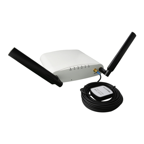
•M510 Dual-Band 802.11ac Wave 2 Access Point with LTE
Backhaul
•GPS antenna
•2 LTE antennas
•T-bar mounting bracket and T-bar mounting clip
•2 plastic wall anchors and #8 mounting screws
•Unit removal pin
•Service Level Agreement/Limited Warranty Statement
•Declaration of Conformity, Regulatory Statement
•This Quick Setup Guide
FIGURE 1 M510 Access Point
Sold Separately
The following optional accessories are sold separately.
•12V DC power supply
•Flange Mount Bracket Kit
Required Hardware and Tools
•No. 2 Phillips screwdriver
•T8 Security Torx driver for SIM slot cover
•802.3af or 802.3at-compliant Power over Ethernet (PoE) switch
or PoE injector for PoE power
•Electric drill with drill bit for at-surface mounting
Initial Setup
Perform the initial setup depending on your deployment
scenario.
The M510 can be connected to WAN via LTE or via Ethernet (with
the LTE connection as a backup for WAN failover).
Attach the two LTE antennas and (optionally) the GPS antenna,
and perform the initial setup according to your deployment
scenario:
•Mobile Environment: M510 congured as Master AP in Gateway
Mode with an LTE connection as the uplink WAN port.
•LTE Backup Environment: M510 in Gateway Mode with the
Ethernet port as the WAN port and the LTE connection as the
backup WAN port, only one of which can be active at any time.
If the Ethernet connection goes down, the LTE connection
becomes active to provide a backup internet uplink.
NOTE: If you are using Ethernet as the primary WAN link with
LTE as a backup, connect an Ethernet cable to the WAN port.
NOTE: M510 does not support deployment as the Master AP
in Bridge mode or as a member AP. Only Master AP in
Gateway mode is supported.
NOTE: Write down the IMEI number of the M510, printed on
the gift box, and also on the AP. This may be required by your
mobile service provider to activate your data plan.
Inserting the SIM Cards
Plug an activated SIM card into the primary slot, and
optionally, a second SIM card into secondary slot for
redundancy.
FIGURE 2 Rotate SIM card cover, insert SIM card(s)
a) Insert the Primary SIM card into the top slot (when the
AP is upright). Ensure that you insert the Primary SIM
card with the copper side facing down, and the notch to
the left side.
b) Insert the Secondary SIM card into the bottom slot.
Ensure that you insert the secondary SIM card with the
copper side facing up, and the notch to the right side.
FIGURE 3 The orientation of the two SIM cards is
reversed, be sure to insert them correctly
Copyright © 2018 ARRIS Enterprises LLC. All rights reserved. Page 1 of 4
Published December 2018, Part Number 800-71989-001 Rev A
NOTE: The M510 supports Micro-SIM sized SIM cards only.
The orientation of the SIM cards is dierent, be sure to
insert the SIM cards correctly. Inserting the SIM cards
incorrectly will result in the inability to use the LTE
functionality.
NOTE: If the SIM card is inserted or replaced after bootup,
a reboot is required.
Unleashed Network Conguration
Setup Using the Unleashed Mobile App
To perform setup using the Unleashed Mobile App, download the
iOS or Android app from the app store.
1. As soon as the Unleashed AP is powered on and connected
to the local network, it boots up and begins broadcasting a
temporary unencrypted WLAN named “Congure.Me-
[xxxxxx]” from both radios.
2. Using your client’s Wi-Fi connection settings, select and
associate to the “Congure.Me-[xxxxxx]” WLAN.
3. Launch the app, and follow the on-screen instructions to
congure your Unleashed network(s).
FIGURE 4 Unleashed Mobile App for iOS and Android
FIGURE 5 Conguring Unleashed from the Mobile App
Setup Using a Web Browser
1. As soon as the Unleashed AP is powered on and connected
to the local network, it boots up and begins broadcasting a
temporary unencrypted WLAN named “Congure.Me-
[xxxxxx]” from both radios.
2. Using your client’s Wi-Fi connection settings, select and
associate to the “Congure.Me-[xxxxxx]” WLAN.
3. Launch a web browser and enter the following into the
browser’s URL bar: unleashed.ruckuswireless.com, and press
Enter.
4. You will be redirected to the Setup Wizard. Complete the
steps in the Setup Wizard and click Finish.
FIGURE 6 Complete the Setup Wizard to set up your
Unleashed network
5. Once the Setup Wizard is nished, a “Conguring system
settings and rebooting” progress screen appears. Wait until
the process is complete.
6. Connect to the WLAN that you congured in the Setup
Wizard, and click OK to reconnect. You will be redirected to
the Unleashed login screen.
7. Enter your Admin Name and Password to login.
FIGURE 7 The Login page
8. Upon successful login you will be presented with the
Unleashed Dashboard, which displays an overview of your
Ruckus Unleashed network.
Mounting Instructions
Mounting on a Flat Surface
1. Use the Mounting Template on the last page of this Quick
Setup Guide as a template to mark the locations for drill
holes on the mounting surface.
2. Use a 5mm drill bit to drill holes approximately 25mm into
the mounting surface.
3. Insert the anchors and mounting screws into the mounting
surface, leaving approximately 1/4” (6 mm) of the screw
heads protruding for the AP enclosure.
4. To remove the AP, insert the unit removal pin into the hole
on the top of the AP to unlock, then push the AP up to
release the AP enclosure from the mounting screws.
FIGURE 8 Flat surface mounting
Copyright © 2018 ARRIS Enterprises LLC. All rights reserved. Page 2 of 4
Published December 2018, Part Number 800-71989-001 Rev A
Mounting on a Recessed Drop-Ceiling T-Bar
NOTE: This mounting bracket can also be used on a ush
drop-ceiling T-bar, so the four rubber feet on the bottom of
the AP minimize ceiling tile displacement.
To mount the AP using the external T-bar bracket:
1. Position the studs on the bottom of the T-bar bracket (B) in
the mounting holes on the AP enclosure (A), and then slide
the T-bar bracket until the studs are in the narrow parts of
the AP mounting keyholes. The mounting bracket locks in
place on the AP enclosure.
FIGURE 9 Attaching the external bracket to the AP
2. Attach the locking tab (C) to one side of the T-bar and the
bracket (B) to the other side of the T-bar.
3. Slide the locking tab (C) into the bracket (B) so that it locks in
place around the T-bar. Make sure that both clasps are
gripping the T-bar.
FIGURE 10 Attaching the external bracket to the T-bar
Removing an External Bracket from a T-Bar
1. Move the ceiling tiles out of the way.
2. Slide the locking tab away from the T-bar to release the AP-
bracket assembly from the T-bar.
3. The AP bracket assembly comes away from the T-bar.
FIGURE 11 Removing the external bracket from the T-
bar
Removing the External Bracket from the AP
1. Insert the unit removal pin into the hole on the front of the
AP to unlock the mounting bracket from the AP enclosure.
2. Slide the mounting bracket toward the Ethernet ports on the
AP until it detaches from the AP.
FIGURE 12 Removing the external bracket from the AP
Attaching the GPS Antenna
The M510 includes an external GPS antenna that can be used for
device tracking in use cases such as in-vehicle Wi-Fi installations.
The GPS antenna has a magnet so that it can be attached
anywhere on the vehicle, and receives power through the RF
cable connected to the M510.
1. Connect the GPS antenna cable to the GPS cable connector
on the M510.
2. Mount the GPS antenna to any surface. The antenna can be
mounted to the roof of the vehicle for optimal GPS signal
reception, or near a window inside the vehicle if roof
mounting is impractical.
3. Log into the AP or controller web interface to verify the GPS
coordinates.
FIGURE 13 M510 external GPS antenna
For More Information
For more information on conguration, administration and
operation of the AP, refer to the Ruckus Wireless Indoor Access
Point User Guide, available from the Ruckus Support website:
support.ruckuswireless.com.
© 2018 ARRIS Enterprises LLC. All rights reserved.
ARRIS, the ARRIS logo, Ruckus, Ruckus Wireless, the Ruckus logo, and
the Big Dog design are trademarks of ARRIS International plc and/or
its aliates. All other trademarks are the property of their respective
owners.
Copyright © 2018 ARRIS Enterprises LLC. All rights reserved. Page 3 of 4
Published December 2018, Part Number 800-71989-001 Rev A
Copyright © 2018 ARRIS Enterprises LLC. All rights reserved. Page 4 of 4
Published December 2018, Part Number 800-71989-001 Rev A
Other Arris Wireless Access Point manuals

Arris RUCKUS R750 User manual

Arris

Arris RUCKUS R750 User manual

Arris Touchstone WECB460 User manual

Arris

Arris Touchstone WECB460 User manual

Arris RUCKUS H320 User manual

Arris

Arris RUCKUS H320 User manual

Arris VAP2500 User manual

Arris

Arris VAP2500 User manual

Arris SPACE CONNECT VAP4641 User manual

Arris

Arris SPACE CONNECT VAP4641 User manual

Arris Ruckus T310n User manual

Arris

Arris Ruckus T310n User manual

Arris RUCKUS R510 User manual

Arris

Arris RUCKUS R510 User manual

Arris Ruckus Unleashed R320 User manual

Arris

Arris Ruckus Unleashed R320 User manual

Arris RUCKUS M510 User manual

Arris

Arris RUCKUS M510 User manual

Arris Ruckus Unleashed T310d User manual

Arris

Arris Ruckus Unleashed T310d User manual

Arris Ruckus T811-CM User manual

Arris

Arris Ruckus T811-CM User manual

Arris RUCKUS ZoneDirector 1200 User manual

Arris

Arris RUCKUS ZoneDirector 1200 User manual

Arris RUCKUS T750 User manual

Arris

Arris RUCKUS T750 User manual

Arris SPACE CONNECT VAP4641 User manual

Arris

Arris SPACE CONNECT VAP4641 User manual

Arris Ruckus R730 User manual

Arris

Arris Ruckus R730 User manual

Arris Ruckus Q410 User manual

Arris

Arris Ruckus Q410 User manual

Arris Ruckus E510 User manual

Arris

Arris Ruckus E510 User manual

Arris SPACE CONNECT VAP4641 User manual

Arris

Arris SPACE CONNECT VAP4641 User manual

Arris Ruckus T310c User manual

Arris

Arris Ruckus T310c User manual

Arris RUCKUS T310s User manual

Arris

Arris RUCKUS T310s User manual

Arris VAP3400 User manual

Arris

Arris VAP3400 User manual

Arris RUCKUS T305i User manual

Arris

Arris RUCKUS T305i User manual

Arris RUCKUS C110 User manual

Arris

Arris RUCKUS C110 User manual

Arris RUCKUS Q710 User manual

Arris

Arris RUCKUS Q710 User manual

Popular Wireless Access Point manuals by other brands

EnGenius EOC-8610-S series user manual

EnGenius

EnGenius EOC-8610-S series user manual

Relay2 RA621EX Hardware installation guide

Relay2

Relay2 RA621EX Hardware installation guide

Linksys WAP11 - Instant Wireless Network Access... user guide

Linksys

Linksys WAP11 - Instant Wireless Network Access... user guide

Pegasus ACR-201-G User handbook

Pegasus

Pegasus ACR-201-G User handbook

LevelOne WAP-3101 user manual

LevelOne

LevelOne WAP-3101 user manual

Digisol DG-WA1102NPLV2 user manual

Digisol

Digisol DG-WA1102NPLV2 user manual

EnGenius ECB600 datasheet

EnGenius

EnGenius ECB600 datasheet

Intermec 0100 user manual

Intermec

Intermec 0100 user manual

H3C WA6528X-E installation guide

H3C

H3C WA6528X-E installation guide

D-Link DAP-1533 Quick install guide

D-Link

D-Link DAP-1533 Quick install guide

Sitecom WLX-7000 v1 001 installation guide

Sitecom

Sitecom WLX-7000 v1 001 installation guide

NETGEAR WNAP210 installation guide

NETGEAR

NETGEAR WNAP210 installation guide

AirTies Air 4920 Quick installation guide

AirTies

AirTies Air 4920 Quick installation guide

Anybus WLAN Access Point IP67 Startup guide

Anybus

Anybus WLAN Access Point IP67 Startup guide

Conexant Intersil ISL39300A user manual

Conexant

Conexant Intersil ISL39300A user manual

HFCL ion8i quick start guide

HFCL

HFCL ion8i quick start guide

Ubiquiti UBB quick start guide

Ubiquiti

Ubiquiti UBB quick start guide

Allied Telesis AT-WA7500 Installation and user guide

Allied Telesis

Allied Telesis AT-WA7500 Installation and user guide

manuals.online logo
manuals.online logoBrands
  • About & Mission
  • Contact us
  • Privacy Policy
  • Terms and Conditions

Copyright 2025 Manuals.Online. All Rights Reserved.