NetGain Motors HYPER-DRIVE X1 User manual

USER MANUAL
HYPER-DRIVE X1 INVERTERS
FOR USE WITH
HYPER 9™
&
HYPER 9HV™SYSTEMS
:

HyPer-Drive User Manual Rev.A.1 Copyright © 2023 NetGain Motors, Inc. All Rights Reserved. Page 2 of 71
2
TABLE OF CONTENTS
Inverter Models (ISOlated vs NON-ISOlated Logic)..................................................................................................................... 5
Isolated 12V Logic .................................................................................................................................................................. 5
Non-Isolated logic .................................................................................................................................................................. 5
Photos of ISO vs NON-ISO Inverters....................................................................................................................................... 5
Warning and Caution .................................................................................................................................................................. 6
Safety Information ..................................................................................................................................................................... 6
DISCLAIMER:............................................................................................................................................................................... 7
Standard K1 Wire Harness - Pinout............................................................................................................................................. 8
Wiring Diagram Overview ........................................................................................................................................................... 9
Important Note on Motor Calibration! ...................................................................................................................................... 9
Isolated Logic - Standard Wiring Diagram................................................................................................................................. 10
Non-Isolated Logic - Standard Wiring Diagram......................................................................................................................... 11
Wiring Instructions - HyPer Motor Plugs................................................................................................................................... 12
Motor Plug Pinout - HyPer Motors............................................................................................................................................ 13
Motor Encoder Pin Positions.................................................................................................................................................... 13
4 Position Ampseal Connector ............................................................................................................................................. 13
Motor Thermistor Pin Positions ............................................................................................................................................... 13
2 Position ampseal Connector.............................................................................................................................................. 13
ISOlated Logic - Main Contactor Wiring.................................................................................................................................... 14
12/24V Coil Driver, High Voltage Contacts, and Key Switch In ................................................................................................ 14
Isolated X1 Main Contactor Wiring...................................................................................................................................... 14
NON-ISOlated –Main Contactor Wiring ................................................................................................................................... 15
24/48V Coil Driver, High Voltage Contacts, and Key Switch In ................................................................................................ 15
NON-ISO Main Contactor wiring .......................................................................................................................................... 15
Main Contactor –Internally Economized Option...................................................................................................................... 16
HV Relay –Wiring Instructions.................................................................................................................................................. 17
HV Relay Drawing..................................................................................................................................................................... 17
HV Relay Terminations ......................................................................................................................................................... 17
Compact Display - wiring instructions....................................................................................................................................... 18
Compact Display Mating Female Plug...................................................................................................................................... 18
Compact Display - 8 Position Connector.............................................................................................................................. 18
Software Files............................................................................................................................................................................ 19

HyPer-Drive User Manual Rev.A.1 Copyright © 2023 NetGain Motors, Inc. All Rights Reserved. Page 3 of 71
3
Download, Extract, and Install the latest TAU SmartView GUI Software: http://www.go-ev.com/downloads/..................... 19
Download the Latest Controller Firmware:.............................................................................................................................. 19
Download the Clone File for Your System: http://www.go-ev.com/downloads/clone_files.html.......................................... 19
Download the FTDI Driver for Serial to USB Adapters: https://www.go-ev.com/downloads/ftdi.zip..................................... 19
Downloading, Extracting, Installing - SmartView ................................................................................................................. 19
Pre-Startup Steps ...................................................................................................................................................................... 21
application checks .................................................................................................................................................................... 21
QuickStart Guide –Wiring and Programming .......................................................................................................................... 21
Post-startup Steps..................................................................................................................................................................... 27
Battery Protection.................................................................................................................................................................... 27
Battery Mapping ...................................................................................................................................................................... 28
Throttle Mapping ..................................................................................................................................................................... 29
Brake Regen Mapping .............................................................................................................................................................. 30
Operating Profiles - Regen on Neutral ..................................................................................................................................... 31
Neutral Torque Mapping.......................................................................................................................................................... 31
Tuning Regen On Neutral –Single Pedal Driving...................................................................................................................... 31
Digital Outputs ......................................................................................................................................................................... 34
Wiring................................................................................................................................................................................... 34
Configuration........................................................................................................................................................................ 34
Temperature Derating –X1 Inverter........................................................................................................................................ 36
Temperature Derating - HyPer Motor...................................................................................................................................... 36
CAN Network Configuration..................................................................................................................................................... 37
Wiring................................................................................................................................................................................... 37
Configuration –CAN NEtwork Settings ................................................................................................................................ 38
Configuration –TPDO’s ........................................................................................................................................................ 38
TPDO STRUCTURE .................................................................................................................................................................... 40
Node Data Type:................................................................................................................................................................... 40
Node Data Type:................................................................................................................................................................... 40
Inverter Information Data Type ........................................................................................................................................... 42
Motor Information Data Type.............................................................................................................................................. 42
Controller Specifications ........................................................................................................................................................... 44
Controller Communication....................................................................................................................................................... 44
Controller EMC......................................................................................................................................................................... 44
Controller Safety Certification.................................................................................................................................................. 44

HyPer-Drive User Manual Rev.A.1 Copyright © 2023 NetGain Motors, Inc. All Rights Reserved. Page 4 of 71
4
Controller Operating Environment Specifications ................................................................................................................... 44
Pre-Programmed I/O - HyPer-Drive Inverter............................................................................................................................. 45
Signal: Inputs and Outputs ....................................................................................................................................................... 45
Controller I/O Table.................................................................................................................................................................. 45
K1 Pin Functions For Non-programmed AC-X1 .................................................................................................................... 45
Datalogging ............................................................................................................................................................................... 48
Datalogging Guide:................................................................................................................................................................... 48
Troubleshooting - Diagnostic Codes.......................................................................................................................................... 50
Fault Levels........................................................................................................................................................................... 50
Fault Code List...................................................................................................................................................................... 50
Additional Support ................................................................................................................................................................... 71

HyPer-Drive User Manual Rev.A.1 Copyright © 2023 NetGain Motors, Inc. All Rights Reserved. Page 5 of 71
5
INVERTER MODELS (ISOLATED VS NON-ISOLATED LOGIC)
This document covers all HyPer-Drive X1 Inverter models with nominal voltages ranging from 36V-144V. The terms
Isolated Logic (ISO) vs Non-Isolated Logic (NON-ISO) are critical in identifying different
HyPer-Drive™
inverters types.
•Isolated Logic: The ISO logic board is energized with 12-24Vdc+. These inverters can be identified by their separate
pre-charge terminal between the V-W terminals. Catastrophic failure will occur if >24V is supplied to any K1
pin.
•Non-Isolated Logic: The NON-ISO logic board is energized with Pack Voltage, in order to pre-charge and key on
through the K1-24 pin. The controller then uses an internal transformer to supply the logic board with 12V. Thus, the
K1 circuit must be completely isolated from all other 12V circuits in the application. These Inverters will
have an indent for the pre-charge terminal between phases V-W, but the indent is not populated with a terminal.
INVERTER TYPE
PART NUMBER
PRODUCT CODES
DC VOLTAGE RANGE
(ABSOLUTE MIN-MAX)
HyPer-Drive ™X144
SRIPM-X144
ACX1T50000I00
ACX1T50000I01
73V –184V
HyPer-Drive ™X1 ISO
SRIPM-X1iso
ACX1S75000I01
45V –132V
HyPer-Drive ™X1 ISO
SRIPM-X125
ACX1S25000I01
45V –132V
INVERTER TYPE
PART NUMBER
PRODUCT CODES
DC VOLTAGE RANGE
(ABSOLUTE MIN-MAX)
HyPer-Drive ™X1
SRIPM-X1
B00AC002200
52V –130V
HyPer-Drive ™X48
SRIPM-X48
ACX1Q60000001
28V –64V
ISOLATED
NON-ISOLATED

HyPer-Drive User Manual Rev.A.1 Copyright © 2023 NetGain Motors, Inc. All Rights Reserved. Page 6 of 71
6
WARNING AND CAUTION
SAFETY INFORMATION
This is not an all-inclusive list. Use common sense and act responsibly, electric motor controllers and
motors are extremely powerful and could cause death, dismemberment or other serious injury if
misused or not safely handled!
Wear protective or safety equipment such as safety shoes, safety glasses, and HV Insulated gloves
when working with motors and controllers.
Remove all metal jewelry and metal objects from hands, wrist, fingers, etc. before working on any
electric motor or controller.
Insulate any tools that are used in proximity to connection points that have any voltage potential to
prevent shorts if the tool is accidentally dropped onto the terminals/connections.
Use caution when operating any controller or motor. If you're not sure what you're doing, or do not
feel comfortable with the situation, find a knowledgeable person to advise you.
Make certain the motor and controller are disconnected from any power source before servicing. If
any doubt exists of the voltage that might exist, measure with proper metering devices that are in
good functional condition, and rated for the voltages that could exist.
Verify and re-verify proper wiring connections.
Take extreme caution around series-connected batteries to avoid placing hands across live
connections. It is generally good practice to avoid the use of both hands when working around high
voltage circuits. This reduces the risk of an accidental short across the chest cavity.
If working on an electric vehicle, make certain the vehicle is positioned securely with the drive wheels
safely clear of the floor and blocked up so that the drive wheels cannot make contact with the floor
under any circumstances. Block the non-drive wheels if they remain in contact with the floor so that
the vehicle cannot roll in either direction.

HyPer-Drive User Manual Rev.A.1 Copyright © 2023 NetGain Motors, Inc. All Rights Reserved. Page 7 of 71
7
Motors and controllers must only be connected to a power source by knowledgeable and experienced
personnel.
Running a motor without a load could result in harm to people or the motor. When applying any
power to motor, motor frame must be securely fastened in place as the toque will cause the motor to
jump.
Portions of the motor or controller may become HOT and proper precautions must be taken.
Motors and controllers should never be operated beyond the limits established by the manufacturer.
Motors and controllers must not be modified in any manner; doing so will void warranty and could
prove extremely dangerous.
Motors are heavy and are likely to become damaged if dropped, or cause damage to anything they fall
upon (including people and body parts). Use extreme caution when working with motors!
Motors contain moving parts that could cause severe injury if the proper precautions are not taken.
Never touch an operating motor.
Do not defeat any safety circuits or safety devices.
Under no circumstances should you push in any contactor of an electric vehicle while the drive wheels
are in contact with the floor. Pushing in a contactor when the drive wheels are in contact with the
floor can cause serious property damage, personal injury or death.
DISCLAIMER:
NetGain Motors, Inc. has no control of third-party installation procedure or the use of this motor and control
system. Accordingly NetGain Motors, Inc. assumes no liability for vehicle functionality or safety during or after
third party installation of the motor and controller. It is the responsibility of the vehicle designer and
component installer to test and qualify their application and ensure proper safety and functionality. NetGain
Motors, Inc assumes no responsibility for this product in any use.

HyPer-Drive User Manual Rev.A.1 Copyright © 2023 NetGain Motors, Inc. All Rights Reserved. Page 8 of 71
8
STANDARD K1 WIRE HARNESS - PINOUT
Must Be
Assigned

HyPer-Drive User Manual Rev.A.1 Copyright © 2023 NetGain Motors, Inc. All Rights Reserved. Page 9 of 71
9
WIRING DIAGRAM OVERVIEW
Before continuing any further, be certain you have identified your inverter type on Page 5. From this point forward,
you will need to know whether to use the instructions for ISO or NON-ISO logic boards. Important Notes:
•Know the Voltage ranges for Inverter terminals and related components.
•Inverter must command a main contactor in the HV circuit. Before closing its main contactor, the Inverter must
Precharge. For more information, see Isolated logic Main Contactor Wiring or NON-ISO X1 Main Contactor Wiring
•HV Relay wiring –an HV Relay is included in each Wire Harness Kit. This relay can be used as a Key Switch Relay for
NON-ISO Inverters, or as a Precharge Relay for ISOLATED Inverters. For more information, see HV RELAY WIRING
•Please see the following instructions for adding and removing pins (part#770854-1) from the K1 Harness plug
(Part#776164-1) - AMPSEAL Connector Instructions by TE Connectivity:
https://www.youtube.com/watch?v=uXTkm_XV2OY
•It is best to remove the Wire Relief shroud (Part# 776463-1) from the K1 Ampseal plug to view wire position in the
K1 Harness. This wire relief can be slid off the K1 plug after removing the 2 Phillips head screws from the shroud.
•The inverter’s IP Rating is reduced and more susceptible to ingress when the K1 or K3 port are not sealed. Especially
in wet or humid environments, it is important to seal these ports with the K1 plug, K3 cap, or serial cable.
IMPORTANT NOTE ON MOTOR CALIBRATION!
Your inverter’s clone file must be calibrated to your motor before use. Please follow the Pre-Startup steps in
your System’s User Manual to commission the spin sensor before attempting to spin the motor. When you commission a spin
sensor, you are calibrating the existing clone file for the individual motor it is controlling. This calibration is only stored within
the clone file. If your clone file is being modified, you must adhere to one of the following options:
1. Modify the clone file that has already been commissioned to the motor by saving it from SmartView and re-loading it post-
modification.
2. Copy all parameters from the commissioned clone file’s Spin Sensor tab into the un-commissioned clone you are installing.
3. Commission the spin sensor again after installing a different clone file.

HyPer-Drive User Manual Rev.A.1 Copyright © 2023 NetGain Motors, Inc. All Rights Reserved. Page 10 of 71
10
ISOLATED LOGIC - STANDARD WIRING DIAGRAM
ISOLATED
LOGIC ONLY!
If your Inverter has
a terminal between
V-W phases - use
this diagram.
HyPer-Drive User Manual Rev.A.1 Copyright © 2023 NetGain Motors, Inc. All Rights Reserved. Page 11 of 71
11
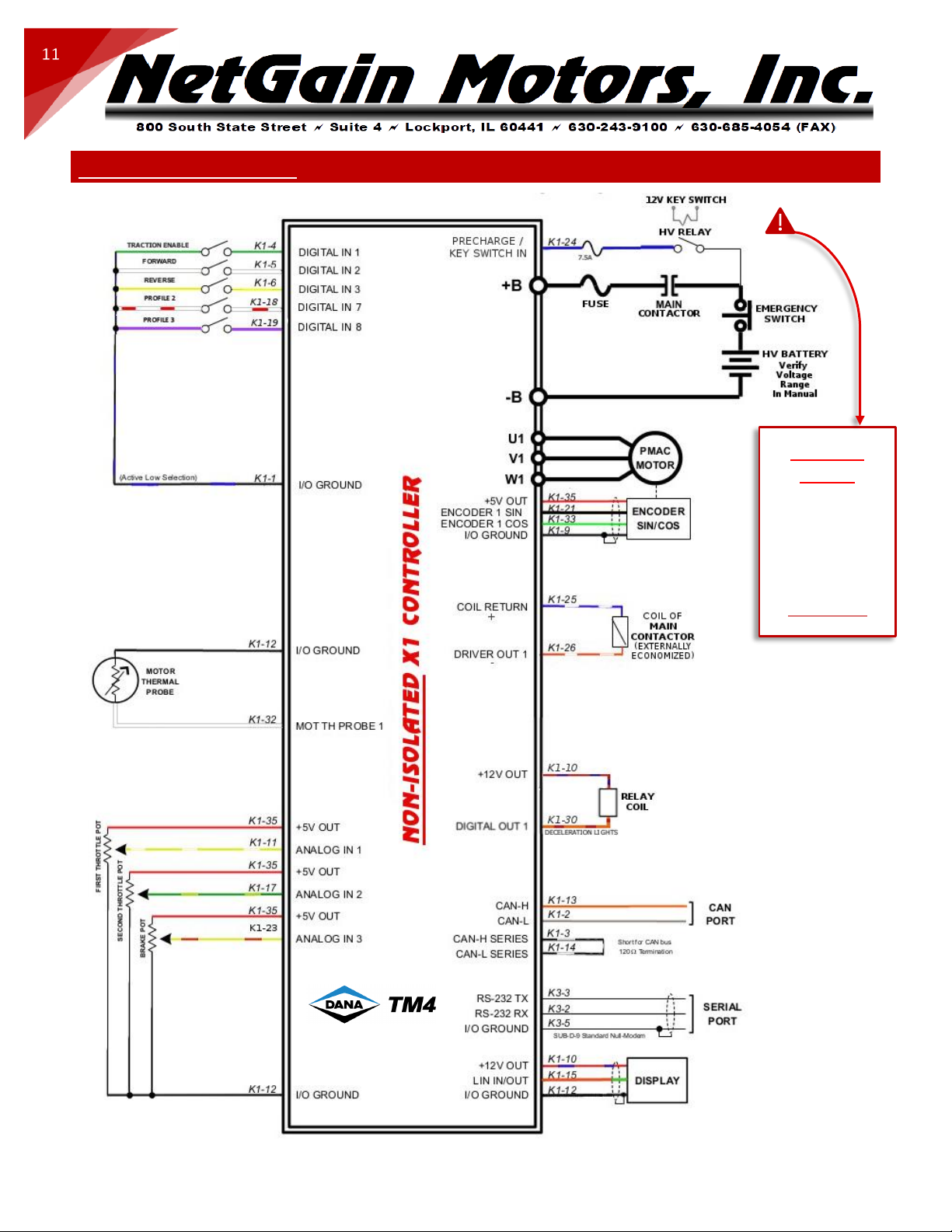
NON-ISOLATED LOGIC - STANDARD WIRING DIAGRAM
NON-ISO
ONLY!
If your Inverter has
a Precharge
terminal between
V-W phases - use
Wiring Diagram for
Isolated Logic
HyPer-Drive User Manual Rev.A.1 Copyright © 2023 NetGain Motors, Inc. All Rights Reserved. Page 12 of 71
12
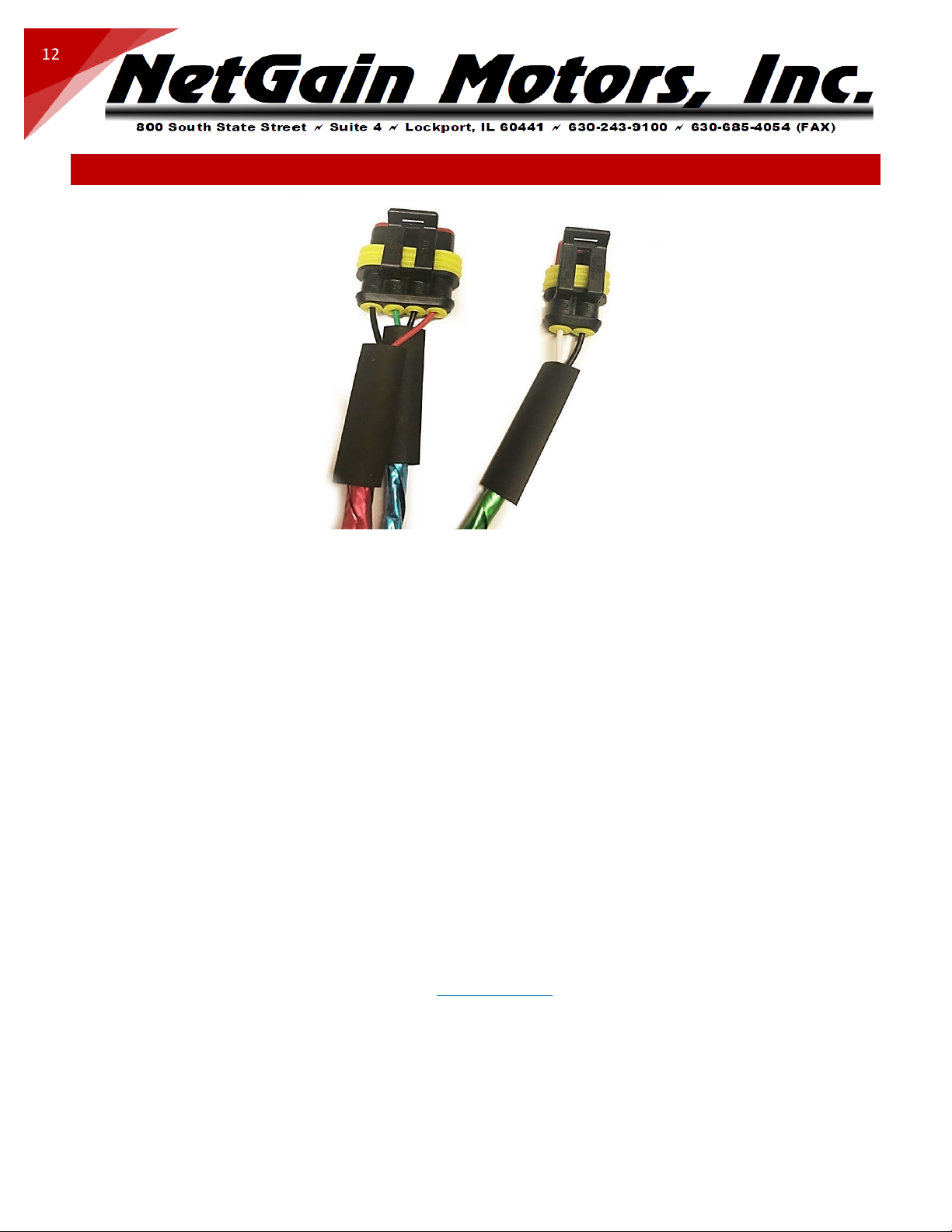
WIRING INSTRUCTIONS - HYPER MOTOR PLUGS
1. Choose a location to fasten the Male 4P and 2P Receptacles from your HyPer Motor.
2. Route multipair cable at least 6 inches from the motor case. Fasten this cable securely so it is restrained from
movement. Line cable up with motor’s Male Receptacles.
3. Using Cable Cutters - trim excess length from multipair cable, leave 4-6” extra to ensure cable will reach motor
Receptacles.
4. Using a co-ax stripper or scissors –carefully strip multipair black jacket at least 4.5” from cable end. This length
should allow 4P and 2P wires to reach their respective Receptacle. Be careful not to cut into the foil shielding or wire
insulation underneath the jacket. A razor blade or X-acto knife can be used to carefully slice a relief strip down the
stripped jacket length, so it can be easily removed.
5. Slide ½” diameter heatshrink over multipair cable. Slide heatshrink past the newly exposed foil, and rest heatshrink
on remaining jacket material for future adhesion.
6. Slide ¼” diameter heatshrink over each of the 3 shielded twisted pairs. Rest heatshrink near jacket for future
adhesion.
7. Peel back 1.5” of foil shield and plastic wrap.
8. Slide yellow Plug Seals onto each wire with the smaller diameter end of each Seal facing the wire end.
9. Strip ¼” of insulation from the end of each 20awg wire.
10. Using an Open Barrell Crimper for “Amp” brand Pins – Crimp the provided “Strip Pins” onto the copper of each wire.
11. Place pins in their proper position according to Motor Plug Pinout on the next page.
12. Fasten the red locking plate on the front of each plug. Verify all six pins are fully inserted.
13. Slide yellow Plug Seals into wire cavities.
14. Plug the newly assembled Plugs into the matching Male Plugs on your HyPer motor.
15. After the pre-start up steps are complete, and correct system operation is verified, apply heat to heatshrink using a
heat gun. Adhere the heatshrink as close to the plug as possible without putting strain on the inserted wires.

HyPer-Drive User Manual Rev.A.1 Copyright © 2023 NetGain Motors, Inc. All Rights Reserved. Page 13 of 71
13
MOTOR PLUG PINOUT -HYPER MOTORS
Important: The Motor Encoder must be mounted securely and restrained from movement. Keep
Encoder wires as far as possible from High Voltage cables and the motor’s field.
MOTOR ENCODER PIN POSITIONS
ENCODER PIN #
NAME
K1 POSITION
4
Encoder I/O Ground
K1-9
3
Encoder Cos 1
K1-33
2
Encoder Sin 1
K1-21
1
+5V
K1-35
MOTOR THERMISTOR PIN POSITIONS
THERMISTOR PIN #
NAME
K1 POSITION
2
Motor Thermistor
K1-32
1
Analog Ground
K1-12
K1-9 K1-33 K1-21 K1-35
Included in HyPer System:
Amp Superseal 4 POS
Plug Part# 282088-1
Pin Part# 282110-1
Seal Part# 281934-2
Included in HyPer 9HV IS:
Amp Superseal 2 POS
Plug Part# 282080-1
Pin Part# 282110-1
Seal Part# 281934-2
K1-32 K1-12

HyPer-Drive User Manual Rev.A.1 Copyright © 2023 NetGain Motors, Inc. All Rights Reserved. Page 14 of 71
14
ISOLATED LOGIC - MAIN CONTACTOR WIRING
12/24V COIL DRIVER, HIGH VOLTAGE CONTACTS, AND KEY SWITCH IN
CONTACTOR TERMINAL
NAME
INVERTER TERMINAL
X1
Coil Return (PWM)
K1-25
X2
Driver Output 1
K1-26
A1+
HV Battery+
B+ Precharge*
A2-
Controller HV+
B+ Terminal*
ALL HV circuit should include proper fuses and disconnect switches. 5A fuse is sufficient for Precharge
circuit. Precharge circuits contain internal resistor.
*The Precharge B+ Terminal can be hard wired to battery pack positive, or switched on via your key
switch using the included HV Precharge relay:
1. Hard wired: Precharge will always see voltage when the high voltage battery pack circuit is closed. This
means less cycles of the controller’s internal Precharge circuit. It will also leave a parasitic drain on your
battery pack. If you will be certain to open a high voltage maintenance switch while leaving the vehicle
unattended for weeks at a time, then this option will work well.
2. HV Precharge Relay: This will Precharge your controller upon startup every time. It will eliminate a
parasitic drain on your High Voltage pack. The key switch must have an On position that energizes the HV
Precharge Relay coil before the key is turned to the Start position, which will close 12V+ to K1-24.
Required Contactor for
ISOLATED LOGIC X1:
12V/24V Coil - External PWM
Part# GV200PA-1 or Equivalent
HyPer-Drive User Manual Rev.A.1 Copyright © 2023 NetGain Motors, Inc. All Rights Reserved. Page 15 of 71
15
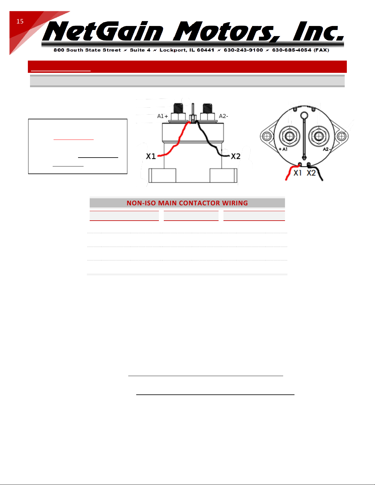
NON-ISOLATED –MAIN CONTACTOR WIRING
24/48V COIL DRIVER, HIGH VOLTAGE CONTACTS, AND KEY SWITCH IN
CONTACTOR TERMINAL
NAME
INVERTER TERMINAL
X1
Coil Return (PWM)
K1-25
X2
Driver Output 1
K1-26*
A1+
Battery + / Precharge
K1-24**
A2-
Controller HV+
B+
ALL HV circuit should include proper fuses and disconnect switches. 7.5A-10A fuse is sufficient for the
NON-ISO Precharge & Logic circuit. Precharge circuits contain internal resistor.
* In our Standard NON-ISO X1 Clone files, Driver Output for the Main Contactor coil is configured for a
48Vd, externally economized coil. All Driver Outputs can be configured from 1-100% of pack voltage, at a
PWM frequency of 125hz-1000hz. For more information, see Driver Outputs.
** NON-ISOLATED Inverters ONLY - full battery pack voltage is supplied to K1-24 (Key Switch In) when the
Ignition Key is switched on. The K1 harness should not have any tie to chassis ground. The HV Key Switch
Relay coil is energized by external 12V, but the HV relay connect pack voltage to K1-24 through its isolated
Normally Open (NO) contacts. K1-24 is the only external voltage source in the K1 harness. The NON-ISO X1
logic board uses internal buck transformers to step down battery pack voltage from pin K1-24 to lower
voltage for internal inputs and outputs. K1 Ground pins trace internally to the X1 inverter’s B- terminal.
Required Contactor for
NON-ISOLATED X1:
12V-96V Coil - External PWM
Part# GV200QA-1 or Equivalent

HyPer-Drive User Manual Rev.A.1 Copyright © 2023 NetGain Motors, Inc. All Rights Reserved. Page 16 of 71
16
MAIN CONTACTOR –INTERNALLY ECONOMIZED OPTION
The Main Contactor Manager must energize a Contactor/Relay Coil with a PWM Output, rather than an
on/off DC voltage. The manufacturer recommends using the X1 Driver Outputs to economize the main contactor
coil’s freewheeling diode. An externally economized main contactor is included with each HyPer System. For
wiring and part# of your externally economized contactor, please see the two previous pages.
Using an internally economized contactor is possible. This requires a cascading relay whose coil is wired
to K1-25 & K1-26, as shown in the diagram below. Your Clone File's Main Contactor voltages, frequency, and pull
in time may require reconfiguration to match the specification of your cascaded relay:
HyPer-Drive User Manual Rev.A.1 Copyright © 2023 NetGain Motors, Inc. All Rights Reserved. Page 17 of 71
17
HV RELAY –WIRING INSTRUCTIONS
An HV Relay is included in all wire harness kits for both ISO and NON-ISO Inverters. This relay can be used for
controller/inverter Precharge and/or Key Switch On. For more information on HV Relay wiring, please follow the Wiring
Diagram and Main Contactor Wiring instructions for your inverter.
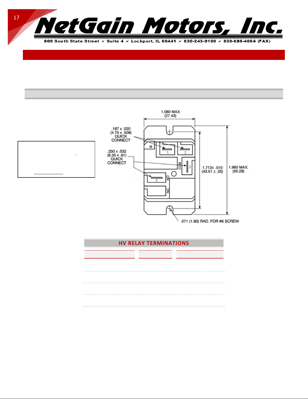
HV RELAY DRAWING
HV RELAY TERMINAL
NAME
TERMINATION
4
NO
HV OUT to Inverter
3
COM
HV IN
2
12V Coil -
12V Key Switch -
1
12V Coil +
12V Key Switch +
Optional for ISO X1,
Required for NON-ISO X1:
HV Relay
Part# T9AP1D52-12 or Equivalent

HyPer-Drive User Manual Rev.A.1 Copyright © 2023 NetGain Motors, Inc. All Rights Reserved. Page 18 of 71
18
COMPACT DISPLAY - WIRING INSTRUCTIONS
The K1-15 LIN-BUS wire is not installed in our standard wire harness. An Orange 18AWG Wire is included
with each Compact Display. This wire is terminated with an Ampseal pin, it must be inserted in position K1-15 of
the K1 Harness.
Please see the following instructions for adding and removing pins from the K1 Harness plug:
https://www.youtube.com/watch?v=uXTkm_XV2OY
For more information, please see Compact Display User Manual.
COMPACT DISPLAY MATING FEMALE PLUG
POSITION
NAME
K1 POSITION
8
+12V Out
K1-10
7
I/O Ground
K1-12
6
Not Connected
N/A
5
LIN-BUS
K1-15
4
Digital Input 1
TBD
3
Digital Input 2
TBD
2
Digital Input 3
TBD
1
Digital Input 4
TBD
4 1
8 5
Included with Compact Display:
Econoseal .070 MK-II 8 POS
Plug Part# 2822393-1 or 174982-2
Pin Part# 171662-1 or 171630-1
Locking Plate Part# 174983

HyPer-Drive User Manual Rev.A.1 Copyright © 2023 NetGain Motors, Inc. All Rights Reserved. Page 19 of 71
19
SOFTWARE FILES
DOWNLOAD, EXTRACT, AND INSTALL THE LATEST TAU SMARTVIEW GUI SOFTWARE:
http://www.go-ev.com/downloads/
DOWNLOAD THE LATEST CONTROLLER FIRMWARE:
http://www.go-ev.com/downloads/firmware
DOWNLOAD THE CLONE FILE FOR YOUR SYSTEM:
http://www.go-ev.com/downloads/clone_files.html
DOWNLOAD THE FTDI DRIVER FOR SERIAL TO USB ADAPTERS:
https://www.go-ev.com/downloads/ftdi.zip
1. DOWNLOAD
2. EXTRACT

HyPer-Drive User Manual Rev.A.1 Copyright © 2023 NetGain Motors, Inc. All Rights Reserved. Page 20 of 71
20
3. OPEN UNZIPPED FILE FOLDER
4. OPEN VOLUME FOLDER
5. OPEN SETUP –APPLICATION
6. INSTALL
7. RESTART PC
Table of contents


