Netkrom AIRNET 11Mb CPE BRIDGE User manual

AIRNET 11Mb CPE BRIDGE
Installation Guide

Copyright © 2005 by Netkrom Technologies Inc.
All rights reserved.
This publication conveys information that is the property of Netkrom Technologies Inc. It shall not be copied,
reproduced or duplicated in whole or in part without the express written permission of Netkrom Technologies Inc.
The information contained herein is subject to change without notice.
Document version 1.0
Published by Netkrom Technologies Inc.
SALES
Address:
Netkrom Technologies Inc.
3152 NW 72nd Ave Miami, FL
33122 U.S.A.
Phone: +1 305-4182232
Fax: +1 305-4182232
TECHNICAL SUPPORT
Address:
Netkrom Technologies Inc.
3152 NW 72nd Ave Miami, FL
33122 U.S.A.
Phone: +1 305-4182232
Fax: +1 305-4182232
INTERNET
Web:
www.netkrom.com
Limited Warranty
Netkrom Technologies Inc. Limited Warranty
Netkrom Technologies Inc. (“Netkrom”) makes the following limited warranty. This limited warranty extends to
the original consumer purchaser and to no other purchaser or transferee.
Limited One (1) Year Parts and Labor Warranty for Netkrom CPE Unit.
Netkrom warrants this product and its parts against defects in materials and/or workmanship for a period of one
(1) year after the date of original retail purchase. During this period, Netkrom will repair or replace a defective
product or part without charge to you.
Warranty Conditions
The above LIMITED WARRANTY is subject to the following conditions:
1.Warranty extends only to products distributed by Netkrom.
2.Warranty extends only to defects in materials and/or workmanship as limited above. Warranty extends only to
defects which occur during normal use and do not extend to damage to products or parts which results from
alternation, repair, modification, faulty installation or service by anyone other than an Authorized Netkrom
Service Center; damage to products or parts caused by accident, abuse, or misuse, or maintenance,
mishandling, misapplication, or use in violation of instructions furnished by us; damage which occurs in shipment
or any damage caused by acts of God, such as lightening or line surges.
3.You must retain your bill of sale or provide other proof of purchase.
4.Any replacement parts furnished at no cost to the purchaser in fulfillment of this warranty are warranted only
for the unexpired portion of the original warranty.

Obtaining Warranty Service
If your Netkrom product is still under warranty, visit the Netkrom website at www.Netkrom.com/rma.htm to
request a return merchandise authorization (“RMA”) number. An RMA number will be issued and emailed to you.
Authorized Netkrom Service Centers or Netkrom will not accept any returned product without an RMA number.
Ship the product to Netkrom, postage prepaid, together with your bill of sale of other proof of purchase, your
name, address, description of the problem(s), and the RMA number you have obtained from Netkrom. All
products returned for warranty service must be carefully packaged in the original packing materials.
ALL WARRANTY REQUIRED TO BE IMPLIED BY STATE LAW ARE EXPRESSLY LIMITED TO THE
DURATION OF THE LIMITED WARRANTY SET FORTH ABOVE.
Some states do not allow limitations on how long an implied warranty lasts, so the above limitation may not apply
to you. WITH THE EXCEPTION OF ANY WARRANTIES REQUIRED TO BE IMPLIED BY STATE LAW AS
HEREBY LIMITED, THE FOREGOING EXPRESS WARRANTY IS EXCLUSIVE AND IN LIEU OF ALL OTHER
WARRANTIES.
IN NO EVENT SHALL Netkrom BE LIABLE FOR SPECIAL, INCIDENTAL, CONSEQUENTIAL OR PUNITIVE
DAMAGES, INCLUDING, WITHOUT LIMITATION, DAMAGE TO THE PROPERTY CAUSED BY ANY DEFECT
IN THIS PRODUCT, INCONVENIENCE, LOSS OF GOODWILL, LOST PROFITS OR REVENUE, LOSS OF
USE OF THIS PRODUCT OR ANY ASSOCIATED EQUIPMENT, COST OF SUBSTITUTIVE EQUIPMENT,
DOWNTIME COSTS OR CLAIMS OF ANY PARTY DEALING WITH PURCHASER FOR SUCH DAMAGES,
RESULTING FROM THE USE OF THIS PRODUCT, OR ANY OTHER LEGAL THEORY. Some states do not
allow the exclusion or limitation of incidental or consequential damages, so the above limitation may not apply to
you.
THIS WARRANTY GIVES YOU SPECIFIC LEGAL RIGHTS, AND YOU MAY HAVE OTHER RIGHTS, WHICH
VARY FROM STATE TO STATE.
For more information, please call (305) 4182232
Federal Communications Commission (FCC) Statement
This equipment has been tested and found to comply with the limits for a Class B Digital Device, pursuant
to Part 15 of the FCC Rules. These limits are designed to provide reasonable protection against harmful
interference in a residential installation.
Any changes or modifications made to this equipment may void a user’s authority to operate this equipment.
This equipment generates, uses, and can radiate radio frequency energy and, if not installed and used in
accordance with the instructions, may cause harmful interference with radio communications.
However, there is no guarantee that interference will not occur in a particular installation.

Table of Contents
Section 1: Introduction.....................................................................................................1
System Overview..................................................................................................1
Safety Precautions ...............................................................................................1
Important Notes ...................................................................................................2
Section 2: Before You Begin............................................................................................3
Verify Contents of Installation Kit .........................................................................3
Tools and Hardware Needed................................................................................3
Section 3: Selecting a Location for the CPE...................................................................4
Section 4: Installing the Netkrom CPE Unit....................................................................5
Assemble the CPE................................................................................................5
Mount the CPE......................................................................................................6
Connect the Cat 5 Cable to Power Supply and PC.............................................. 8
Aim the CPE......................................................................................................... 8
Secure the CPE and Cable ................................................................................. 9
Section 5: Configuring the Netkrom CPE Unit..............................................................11
Operation Mode....................................................................................................11
LOGIN..................................................................................................................11
STATUS................................................................................................................12
System..................................................................................................................12
System Log...........................................................................................................13
Statistics................................................................................................................14
Active Clients.........................................................................................................14
Basic Settings........................................................................................................15
Advanced Settings.................................................................................................16
Security..................................................................................................................19
Access Control.......................................................................................................21
Site Survey.............................................................................................................22
WDS Setting...........................................................................................................22
TCP/IP....................................................................................................................23
Basic.......................................................................................................................23
Web Redirection.....................................................................................................25
DHCP Relay...........................................................................................................25
SNMP.....................................................................................................................26
OTHER...................................................................................................................28
Upgrade Firmware..................................................................................................28
Reboot....................................................................................................................28
Save/Reload Settings.............................................................................................29
Password................................................................................................................30

Pag 1
Section 1: Introduction
The Netkrom CPE Unit offers a cost-effective alternative to accessing the Internet or a corporate network
through expensive dedicated phone lines or fiber networks. It provides the high-performance, cost effective LAN-
to-LAN (local area network) and LAN-to-WAN (wide area network) connectivity that is ideally suited for a
wireless network or wireless Internet access.
System Overview
Wireless data is transmitted from a base station antenna to a receiving antenna called the Netkrom CPE Unit, or
CPE for short. (“CPE” stands for “customer premises equipment.”).
The radio signals used to send and receive data from the CPE is a “line of sight” signal, meaning that data can
only be sent or received if there is an unobstructed path between the central Base Station or remote antenna
and the Netkrom CPE Unit.
Safety Precautions
WARNING! Serious injury or death can occur if proper safety precautions are not taken during the installation of
this equipment.
The U.S. Consumer Product Safety Commission advises consumers to use the following precautions when
installing an antenna.

Site Selection:
Select a safe site to install the CPE.
The distance between any power lines and the installation site should be at least one and one-half times the
height of the CPE and mast assembly. Make the distance even greater, if at all possible. Since all overhead
power lines look somewhat alike, consider them all dangerous and stay well away from them.
If you have power lines in the area, call your local electric utility for assistance.
CPE Mounting:
NEVER work alone; always have someone near who can summon help.
Certain clothing may provide a degree of safety, but don't depend on it for your life (rubber boots or shoes,
industrial rubber gloves and a long sleeve shirt or jacket).
Check weather conditions. Be sure that it hasn't rained recently and that the lawn is not wet or muddy. Make
sure that rain or thunderstorms are not predicted for the day you decide to install the CPE.
The wind can blow the CPE into a nearby power line. Don't install or remove CPE in moderate or heavy winds.
If you need to use a ladder, make sure it is made of non-conductive (non-metallic) material. (This is a safety rule
that you should follow whenever you're working with electrical equipment.)
If possible, have someone present who has been trained in electric shock first aid.
CPE Installation:
Properly assemble the CPE according to instructions (do this where the CPE is to be put up).
Once the CPE is up in full vertical position, securely fasten it by tying it to the side of the house or by using “guy”
wires.
Ground the CPE according to the National Electrical Code.
Rooftop Installations:
DO NOT assume that just because you're on a roof, you're isolated from ground. You may still be electrocuted or
fall off the roof.
Important Notes
Read all instructions prior to installing any of the enclosed equipment. Pay particular attention to the
warnings associated with the installation of the CPE.
It is highly recommended that the installation of this equipment is done by a trained professional if you are
not experienced with installation of communications equipment.
Tampering with or breaking the seal on Netkrom CPE Unit back plate voids any warranty coverage on the
CPE and will result in full equipment charge to the customer.
Pag 2

Pag 3
Section 2: Before You Begin
Verify Contents of Installation Kit
Take a moment to ensure you have all of the following parts in your Netkrom CPE Unit installation kit before you
begin installing the CPE. If any parts are missing, please contact Netkrom at 305-4182232
CPE BRIDGE ONLY CPE BRIDGE POINT TO POINT KIT
1. AIRNET CPE Bridge Unit
2. Antenna Mounting bracket (include: stainless
steel U-Bolts, Flange Nuts, and saddle
clamps)
3. PoE Injector with 100-240v Power supply
4. Product CD
1. (02) AIRNET CPE Bridge Unit
2. (02) Antenna Mounting bracket (include:
stainless steel U-Bolts, Flange Nuts, and
saddle clamps)
5. (02)Wall Mount Bracket
3. (02)PoE Injector with 100-240v Power supply
4. (02)75’ UTP Cat5 Outdoor Cable
5. (02)Product CD
Tools and Hardware Needed
The following tools will be needed to assemble and mount your CPE:
Crescent wrench, channel locks, or a small pipe wrench
Phillips head screw driver
Pipe and other hardware on which to mount the CPE (See Mount the CPE on page 6 for illustration.)
Cable ties and other hardware with which to secure the exterior Cat 5 cable to the CPE and building (See
Secure the CPE and Cable on page 9 for illustration.)

Pag 4
Section 3: Selecting a Location for the CPE
It is very important to position the Netkrom CPE and its antenna(s) to ensure the highest possible data transfer
speed in all kinds of weather and in all seasons. The Netkrom CPE operates on a radio frequency of 2.4 GHz
and must be line-of-sight (LOS) with its clients. Hills, buildings, trees and large vehicles must not block the signal
path. Trees are especially troublesome as they may allow the signal to pass easily in winter when leaves are off,
but may block the signal in the other seasons.
Choose a location on the roof, tower, mast or wall for your Netkrom CPE and antenna(s) so that it has a clear
shot to your base station or remote point. The closest client may not necessarily have the best path if it is
blocked by hills, buildings or trees.
Ensure that the signal path to each client has sufficient Fresnel zone clearance with respect to the ground or
other obstacles near the path. Check the Netkrom FAQ’s under “Radio Propagation” for more information on
Fresnel zone clearance.
Ensure that your mounting location is less than 100 meters from the computer, hub, switch or router location.
(Maximum length of CAT-5 cable is 100 meters) Determine the building entry point ahead of time to prevent
problems later.

Pag 5
Section 4: Installing the Netkrom CPE Unit
This section describes how to assemble and mount your Netkrom CPE Unit.
Assemble the CPE
Note: Tampering with or breaking the seal on the back plate of your CPE voids any warranty coverage on the
CPE.
Do the following to assemble the CPE:
1. Attach the mounting bracket to the back of the CPE using the four hex screws provided. (Do not
overtighten the screws.)
Note: The bracket in the illustration above shows the normal orientation which allows the CPE to be
pointed up towards the base station antenna. However, if you live somewhere that would require you
pointing the CPE down towards the base station antenna (for example, you are on the side of a
mountain in view of the base station antenna below), reverse the bracket so the Netkrom CPE Unit can
be “tilted” downward when you aim the CPE in a later step.
2. Remove the U-bolt and pipe bracket assembly from the pink plastic. Place the washer, lock washer and
nut to each side of the bolt, and then tighten until the bolts are approximately 1/4" from the end.
Note: Do not tighten the screws all the way because you will need to adjust the CPE direction in a later step.

Pag 6
Mount the CPE
WARNING: Netkrom strongly recommends you have a trained professional do the installation if you do not have
experience installing communications equipment. If you choose to install this equipment yourself, you do so at
your own risk.
Do the following to mount the CPE:
1. Review the safety precautions on page 3, and make sure you have all the tools and equipment needed
to install the CPE.
2. Mount the CPE in the Wall Mount Bracket and point the CPE in the approximate direction of the base
station antenna or other CPE for point to point mode, then hand-tighten the nuts on the U-bolt.
3. Mount the CPE to the top of the pipe or other support and point the CPE in the approximate direction
of the base station antenna or other CPE for point to point mode, then hand-tighten the nuts on the U-
bolt.
Note: Do not tighten the screws all the way because you will need to adjust the CPE direction in a later step.

Pag 7
4. Attach the external Cat 5 cable to the back of the CPE: place the round cable connection on the cable
with the round jack on the back of the CPE, gently twist the cable until it slides down, then tighten the
locking ring by turning it to the right (clockwise) until it is finger-tight. The connector has a guide key and
can only go on one way.
Note: It is important to keep all connections clean and dry. While the connection is water resistant,
getting moisture or debris in the connection will reduce or prevent transmission speed.
1 2
3
Note: Do not secure the exterior Cat 5 cable to the CPE or to the building at this time. You will do this
after you have completed aiming the CPE in a later step.
5. Run the exterior Cat 5 cable from the CPE into the house. Determine the Cat 5 cable length needed
inside the house to reach from the wall where it enters the house to the computer. Add some slack
(about 3 feet) then coil the excess Cat 5 cable. DO NOT CUT OFF THE EXCESS CABLE.
WARNING! If a hole is to be made in the exterior wall of the building, use extreme caution to avoid interior
wiring, plumbing and other potential hazards. If the installer is not absolutely sure of the location of potential
hazards, consult a qualified electrical contractor to install the exterior Cat 5 cable.

Pag 8
Connect the Cat 5 Cable to Power Supply and PC
Do the following to connect the CPE to the power supply and to your PC:
1. Connect the end of the exterior Cat 5 cable to the of the Power over Ethernet - PoE Injector connection
marked “DATA/ POWER OUT” (CPE). (The PoE Injector supplies the power (Direct Current) needed to
get the signal to your PC.)
2. Connect the power cord to the power supply, then connect one end of the power supply to the PoE
Injector (see illustration above) and plug the power cord into a 110-240v outlet.
3. Do one of the following to connect the PoE Injector to your PC.
IMPORTANT NOTE: Be sure to use the correct cable when connecting the PoE Injector to your PC or network
hub. Your Internet service will not function if you use the wrong cable!
If you are connecting the CPE directly to your computer, connect one end of the Cross-Ever Cat 5 cable to
the open connector on the PoE Injector and the other end of the Cross-Ever Cat 5 cable to the Ethernet
card in your PC.
If you are connecting the CPE to a hub or router so multiple computers can share Internet access, connect
one end of the Regular Cat 5 cable to the open connector on the PoE Injector and the other end Regular
Cat 5 cable to the hub or router.
Cross-Over Cable

Pag 9
Aim the CPE
You will need to aim the Netkrom CPE Unit directly at the Base Station or remote antenna to achieve maximum
data speed. Do the following to aim the CPE:
1. Make sure the CPE is loosely mounted, the exterior Cat 5 cable is connected to the CPE the exterior Cat
5 cable is plugged into the ANT side of the PoE Injector, and the PoE Injector is plugged in.
Note: You do not need to plug the Interior Cat 5 cable into your PC network interface card to aim the
CPE, but you must have the Cat 5 cable connected to the PoE Injector and the PoE Injector plugged in
for your CPE to acquire the signal from the base station antenna.
2. Locate the base station antenna and aim your CPE directly toward it.
Secure the CPE and Cable
Do the following to secure the CPE and cable:
1. When you have completed aiming the CPE, tighten the CPE mounting bracket securely so the CPE
won’t move in the wind or other weather.
2. Secure the Cat 5 cable the mounting pipe or other support using wire ties or other suitable hardware.
Regular Cable
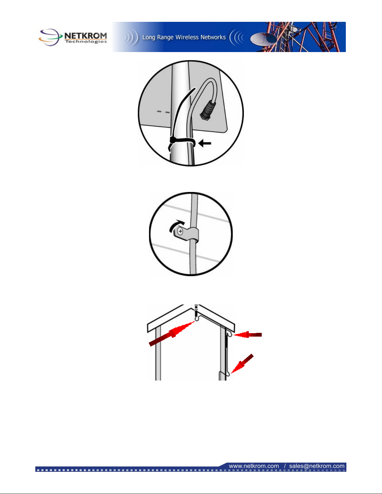
Pag 10
3. Secure the Cat 5 cable to the outside of the house with the cable clamps and 1" stainless steel screws
or other suitable hardware.
Note: Create a “drip loop” wherever the cable changes from vertical to horizontal to prevent water
from traveling down the cable and into the building.
Note: Be careful when bending the cable in cold temperatures so the outer jacket doesn’t crack.
4. Pull any excess cable into the building (except for the drip-loops), and then weather seal the hole around
the Cat 5 cable by applying a quality exterior grade sealant entirely around the Cat 5 cable at the point
where it enters the house.
5. Keep the remainder of the Cat 5 cable kink-free by coiling any extra cable inside and securing it with
a black wire tie.
Dri
p
Loo
p
Dri
p
Loo
p
Dri
p
Loo
p

Pag 11
Section 5: Configuring the Netkrom CPE Unit
Operation Mode
This device provides four operational applications with Access Point, Bridge, Client (Ad-hoc) and Client
(Infrastructure) modes, which are mutually exclusive. for CPE Outdoor Application, only configure in two modes:
Point to Point Bridge
Refer to the illustration below. While acting as Bridges, CPE in building 1 (with Station 1 being associated to)
and CPE in building 2 (with Station 2 being associated) can communicate with each other through wired or
wireless interface (with WDS). Thus Station 1 can communicate with Station 2 and both Station 1 and Station 2
are able to access the Internet if only CPE in building 1 or CPE in building 2 has the Internet connection. To set
the operation mode to Bridge, please go to “Wireless --- Basic Settings”, in the “Mode” field click the down
arrow to select AP mode. And go to “Wireless --- WDS Settings” to enable WDS.
Note: Please make sure both CPE in building 1 and CPE in building 2 are set to the same ESSID and channel
CPE Client Infrastructure
If set to Client (Infrastructure) mode, this device can work like a wireless station when it’s connected to a
computer so that the computer can send packets from wired end to wireless interface. Refer to the illustration
below. This station (CPE plus the connected computer 1) can associate to another Access Point (Base Station),
and then can have the Internet access if the other Access Point (Base Station) has the Internet connection. To
set the operation mode to Client (Infrastructure), please go to “Wireless --- Basic Settings”, in the “Mode” field
click the down arrow to select Client mode, and then select “Network Type” as “Infrastructure”.

Pag 12
Login
1. Start your computer. Connect an Ethernet cable between your computer and the Wireless Access Point.
2. Make sure your wired station is set to the same subnet as the Wireless Access Point, i.e. 192.168.100.12.
3. Start your WEB browser. In the Address box, enter the following:
HTTP://192.168.100.252
The configuration menu is divided into four categories: Status, Wireless, TCP/IP, and Other settings. Click on the
desired setup item to expand the page in the main navigation pane. The setup pages covered in this utility are
described below.
Status
In this screen, you can see the current settings and status of this Access Point. You can change settings by
selecting specific tab described in below.
System

Pag 13
System
Alias Name You can assign a unique name to this Access Point. The alias name is
especially important for identification when there are more than one
Access Point is applied in a network.
Uptime The time period since the device was up.
Firmware Version The current version of the firmware installed in this device.
Wireless Configuration
Wireless Mode There are four modes supported, Access Point, Client (Ad-hoc and
Infrastructure), and Bridge. The default mode is Access Point. If you
want to change to bridge mode, please go to Wireless/WDS Setting to
enable the WDS function.
SSID Sensitive and must not exceed 32 characters. A device will not be
permitted to join the BSS unless it can provide the unique SSID. An
SSID is also referred to as a network name because essentially it is a
name that identifies a wireless network.
Channel Number: The number of channels supported depends on the region of this Access
Point. All stations communicating with the Access Point must use the
same channel.
Encryption WEP Encryption (Wired Equivalent Privacy) is set to Disabled by
default. When WEP is enabled, data packet is encrypted before being
transmitted. The WEP prevents data packets from being eavesdropped
by unrelated people. By using WEP data encryption, there may be a
significant degradation of the data throughput on the wireless link.
Associated Clients Displays the total number of clients associated to this AP. You can have
up to 64 clients to associate to this Access Point.
BSSID BSSID displays the ID of current BSS, which uniquely identifies each
BSS. In AP mode, this value is the MAC address of this Access Point.
TCP/IP Configuration
IP Protocol Display the method to get the IP of this AP, which could be
obtained by Fixed-IP or DHCP-client.
br0 IP Address Current IP address for this Access Point
br0 Subnet Mask Current Subnet mask for this Access Point
br0 Default Gateway Default Gateway for this Access Point
br0 MAC Address The MAC Address for this Access Point
System Log
This page display log events with time when events happened, log events’ types, log sources and the description
for events themselves. System manager can use the system log to trace when problems occur.

Pag 14
Statistics
The Statistics table shows the packets sent/received over wireless and Ethernet LAN respectively.
Active Clients
This page display wireless stations that are associated to this Access Point, with information of their MAC
addresses, transmitted/received packets, transmitting rate, power saving mode, and expired time.
Press Refresh to get the latest information.

Pag 15
Basic Settings
This page includes all primary and major parameters. Any parameter change will cause the device to reboot for
the new settings to take effect.

Pag 16
Alias Name: Maximum 32 characters alpha-numeric You can assign a unique name
to this Access Point. The alias name is especially useful for identification
when there are more than one Access Point is applied in a network.
Disable Wireless LAN Interface: Check the box to disable the Wireless LAN Interface, by so doing, you
won’t be able to make wireless connection with this Access Point in the
network you are located. In other words, this device will not be visible by
any wireless station.
Mode: This Wireless Access Point can support four modes AP, Client (Ad-
hoc), Client (Infrastructure), and Bridge.
The default is set to AP mode. In the “Mode” field Click the pull down
arrow then you can change it to Client mode.
To change to Bridge mode, you will have to set to AP mode, and go to
Wireless/WDS setting to enable WDS.
Network Type: When in Client mode, you can select between Ad-Hoc and
Infrastructure.
SSID: The SSID differentiates one WLAN from another, therefore, all access
points and all devices attempting to connect to a specific WLAN must
use the same SSID. It is case-sensitive and must not exceed 32
characters. A device will not be permitted to join the BSS unless it can
provide the unique SSID. An SSID is also referred to as a network name
because essentially it is a name that identifies a wireless network.
Channel Number: Allow user to set the channel manually or automatically.
If set channel manually just select the channel you want to specify.
If “Auto” is selected, user can set the channel range to have Wireless
Access Point automatically survey and choose the channel with best
situation for communication.
The number of channels supported depends on the region of this Access
Point. All stations communicating with the Access Point must use the
same channel.
From Channel: To Channel: When select “Auto” in “Channel Number, you have to set a range of
channels for the Access Point to automatically survey and choose the
channel for optimal performance.
Allowed Clients Enter a number ranging from 1 to 64.
Apply Change Press to save the new settings on the screen.
Reset Press to discard the data you have entered since last time you press
Apply Change.
Advanced Settings
It is not recommended that settings in this page to be changed unless advanced users want to change to meet
their wireless environment for optimal performance.
Table of contents
Other Netkrom Antenna manuals

Popular Antenna manuals by other brands

TERK Technologies
TERK Technologies FDTV2 owner's manual

Ubiquiti
Ubiquiti AM-5AC22-45 quick start guide

TracVision
TracVision Track Vision M9 manual

Comet Antenna
Comet Antenna UHV-6 Operation manual

zBoost
zBoost Pro 10K SL ZBC745SL Setup overview

Teleco
Teleco Flat Sat Classic Smart 85 Installation guide and user's manual


