netvox R718N360 User manual

Wireless 3-Phase Current Meter Interface
R718N360
Wireless 3-Phase
Current Meter Interface
R718N360
User Manual
Copyright© Netvox Technology Co., Ltd.
This document contains proprietary technical information which is the property of NETVOX Technology. It shall be maintained
in strict confidence and shall not be disclosed to other parties, in whole or in part, without written permission of NETVOX
Technology. The specifications are subject to change without prior notice.

1
Table of Contents
1. Introduction......................................................................................................................2
2. Appearance.......................................................................................................................2
3. Features............................................................................................................................3
4. Setup Instruction ..............................................................................................................3
5. Data Report ......................................................................................................................5
5.1 Example of ReportDataCmd......................................................................................5
5.2 Example of ConfigureCmd ........................................................................................7
5.3 Set/GetSensorAlarmThresholdCmd...........................................................................8
5.4 Example for MinTime/MaxTime Logic.....................................................................9
6. Installation......................................................................................................................10
7. Information about Battery Passivation...........................................................................13
7.1 To determine whether a battery requires activation..................................................13
7.2 How to activate the battery ......................................................................................13
8. Important Maintenance Instruction ................................................................................13

2
1. Introduction
R718N360 is 3-Phase Current Meter Interface device for Netvox Class A devices based on the LoRaWAN open protocol and
is compatible with the LoRaWAN protocol.
LoRa Wireless Technology:
LoRa is a wireless communication technology famous for its long-distance transmission and low power consumption.
Compared with other communication methods, LoRa spread spectrum modulation technique greatly extend the communication
distance. It can be widely used in any use case that requires long-distance and low-data wireless communications. For example,
automatic meter reading, building automation equipment, wireless security systems, industrial monitoring. It has features like
small size, low power consumption, long transmission distance, strong anti-interference ability and so on.
LoRaWAN:
LoRaWAN uses LoRa technology to define end-to-end standard specifications to ensure interoperability between devices and
gateways from different manufacturers.
2. Appearance
Indicator
Function Key

3
3. Features
⚫SX1276 wireless communication module
⚫2 x ER14505 3.6V Lithium battery
⚫3-phase current raw data detection
⚫Magnetic base
⚫IP53 main body
⚫LoRaWANTM Class A compatible
⚫Frequency Hopping Spread Spectrum (FHSS)
⚫Third-Party online wireless sensor monitoring and notification system to configure sensors, view data and set alerts via SMS
text and email (optional)
⚫Available third-party platforms: Actility/ThingPark, TTN, MyDevices/Cayenne
⚫Low power consumption and longer battery life
Note: Please refer to http://www.netvox.com.tw/electric/electric_calc.html for more information of battery lifespan at different
configurations.
4. Setup Instruction
On/Off
Power on
Insert batteries. (users may need a screwdriver to open)
Turn on
Press and hold the function key for 3 seconds until the green indicator flashes once.
Turn off (Reset to factory setting)
Press and hold the function key for 5 seconds until green indicator flashes 20 times.
Power off
Remove Batteries.
Note: 1.The device will be off after removing the battery and insert it again.
2. It is suggested to wait at least 10 seconds between turning the device on and off.
3. 5 seconds after power on, the device will be in engineering test mode.
Network Joining
Never joined the network
Turn on the device and search for the network to join.
The green indicator light stays on for 5 seconds: Success
The green indicator light remains off: Fail
Had joined the network
(without resetting to factory setting)
Turn on the device and search for the previous network to join.
The green indicator light stays on for 5 seconds: Success
The green indicator light remains off: Fail

4
Fail to Join the Network
1. Please remove batteries if the device is not in use.
2. Please check the device verification information on the gateway or consult your
platform server provider.
Function Key
Long press for 5 seconds
Back to default setting / Power off
The green indicator light flashes 20 times: Success
The green indicator light remains off: Fail
Short press
In the network: the green indicator light flashes once and sends a report
Not in the network: the green indicator light remains off
Sleeping Mode
The device is on and in the network.
Sleep period: Min Interval.
When the reportchange exceeds setting value or the state changes: send a data report
according to Min Interval.
The device is on but not in the network.
1. Please remove batteries if the device is not used.
2. Please check device verification on the gateway.
Low Voltage Warning
Low Voltage
3.2V

5
5. Data Report
Data report configuration and sending period are as follows:
5.1 Example of ReportDataCmd
Fport: 0x06
Bytes
1
1
1
Var (Fix=8 Bytes)
Version
DeviceType
ReportType
NetvoxPayLoadData
Version–1 bytes –0x01——the Version of NetvoxLoRaWAN Application Command Version
DeviceType –1 byte –Device Type of Device
The devicetype is listed in Netvox LoRaWAN Application Devicetype V1.9.doc
ReportType –1 byte –the Presention of the NetvoxPayLoadData,according the devicetype
NetvoxPayLoadData–Fixed bytes (Fixed =8bytes)
Before any configuration is made, the device sends data according to the default configuration.
The device will immediately send a version packet report along with two uplink packets including battery voltage and raw data of
three-phase current.
Default setting:
Maximum time: Max Interval =60 min (3600 s)
Minimum time: Min Interval =60 min (3600 s)
*The interval between min time and max time must be greater than 20 seconds.
Note:
(1)The device report interval will be programmed based on the default firmware which may vary.
(2)If the MinTime configuration is less than 20 seconds, it will configure 20 seconds.
(3)R718N360 series would take about 3 seconds for the CT to sample and process the collected value, If the current changes
frequently, the sampling result might be wrong.
Please refer Netvox LoRaWAN Application Command document and Netvox Lora Command Resolver
http://cmddoc.netvoxcloud.com/cmddoc to resolve uplink data.
Min. Interval
(Unit: second)
Max. Interval
(Unit: second)
Reportable Change
Current Change≥
Reportable Change
Current Change<
Reportable Change
Any number between
1 to 65535
Any number between
1 to 65535
Can not be 0.
Report
per Min. Interval
Report
per Max. Interval

6
Tips
1. Battery Voltage
The voltage value is bit 0 ~ bit 6, bit 7=0 is normal voltage, and bit 7=1 is low voltage.
Battery=0xA0, binary=1010 0000, if bit 7= 1, it means low voltage.
The actual voltage is 0010 0000 = 0x20 = 32, 32*0.1v =3.2v
2. Version Packet
When Report Type=0x00 is the version packet, such as 01CA000A02202306050000, the firmware version is 2023.06.05.
3. Data Packet
When Report Type=0x01 is data packet.
(If the device data exceeds 11 bytes or there are shared data packets, the Report Type will have different values.)
Device
Device
Type
Report
Type
NetvoxPayLoadData
R718N360
0xCA
0x01
Battery
(1Byte,
unit:0.1V)
ChannelARawData
(4Bytes)
ThresholdAlarm(1Byte,
Bit0_Low ChannelARawData Alarm,
Bit1_High ChannelARawData Alarm,
Bit2_ Low ChannelBRawData Alarm,
Bit3_ High ChannelBRawData Alarm,
Bit4_ Low ChannelCRawData Alarm,
Bit5_ High ChannelCRawData Alarm,
Bit6-7:Reserved)
Reserved
(2Bytes,
fixed 0x00)
0x02
ChannelBRawData(4Bytes)
ChannelCRawData(4Bytes)
Example 1 of Uplink: 01CA019F000002A9000000
1st byte (01): Version
2nd byte (CA): DeviceType –0xCA –R718N360
3rd byte (01): ReportType
4th byte (9F): Battery –3.1V Battery=0x9F, binary=1001 1111, if bit 7= 1, it means low voltage.
The actual voltage is 0010 0000 = 0x1F = 31, 31*0.1v =3.1v
5th - 8th (000002A9): ChannelARawData –681 681 (Dec) = 000002A9 (Hex)
9th byte (00): ThresholdAlarm –NoAlarm
10th -11th byte (0000): Reserved

7
Example 2 of Uplink: 01CA02000002AB000002A1
1st byte (01): Version
2nd byte (CA): DeviceType –0xCA –R718N360
3rd byte (02): ReportType
4th - 7th (000002AB): ChannelBRawData –683 683 (Dec) = 000002AB (Hex)
8th -11th byte (000002A1): ChannelBRawData –673 673 (Dec) = 000002A1 (Hex)
5.2 Example of ConfigureCmd
FPort:0x07
Bytes
1
1
Var(Fix =9 Bytes)
CmdID
DeviceType
NetvoxPayLoadData
CmdID–1 byte
DeviceType–1 byte –Device Type of Device
NetvoxPayLoadData–var bytes (Max=9bytes)
Description
Device
Cmd
ID
Device
Type
NetvoxPayLoadData
Config
ReportReq
R718N360
0x01
0xCA
MinTime
(2bytes, Unit: s)
MaxTime
(2bytes, Unit: s)
RawDataChange
(4bytes)
Reserved
(1byte, Fixed 0x00)
Config
ReportRsp
0x81
Status
(0x00_success)
Reserved
(8Bytes, Fixed 0x00)
ReadConfig
ReportReq
0x02
Reserved (9Bytes, Fixed 0x00)
ReadConfig
ReportRsp
0x82
MinTime
(2bytes, Unit: s)
MaxTime
(2bytes, Unit: s)
RawDataChange
(4bytes)
Reserved
(1bytes, Fixed 0x00)
(1)Configure device parameters MinTime = 1min, MaxTime = 1min, CurrentChange = 100mA
Downlink: 01CA003C003C0000006400
Response:
81CA000000000000000000 (Configuration successful)
81CA010000000000000000 (Configuration fail)
(2)Read device configuration parameters
Downlink: 02CA000000000000000000
Response:
82CA003C003C0000006400 (current device parameters)

8
5.3 Set/GetSensorAlarmThresholdCmd
Fport:0x10
CmdDescriptor
CmdID
(1Byte)
Payload(10Bytes)
SetSensorAlarm
ThresholdReq
0x01
Channel(1Byte,
0x00_Channel1,
0x01_Chanel2,
0x02_Channel3,etc)
SensorType(1Byte,
0x00_Disable ALL
SensorthresholdSet
0x27_Current,
SensorHighThreshold
(4Bytes,Unit:same as
reportdata in fport6,
0Xffffffff_DISALBLEr
HighThreshold)
SensorLowThreshold
(4Bytes,Unit:same as
reportdata in fport6,
0Xffffffff_DISALBLEr
HighThreshold)
SetSensorAlarm
ThresholdRsp
0x81
Status
(0x00_success)
Reserved (9Bytes,Fixed 0x00)
GetSensorAlarm
ThresholdReq
0x02
Channel(1Byte,
0x00_Channel1,
0x01_Chanel2,
0x02_Channel3,etc)
SensorType
(1Byte,Same as the
SetSensorAlarmThresholdReq’s
SensorType)
Reserved (8Bytes,Fixed 0x00)
GetSensorAlarm
ThresholdRsp
0x82
Channel(1Byte,
0x00_Channel1,
0x01_Chanel2,
0x02_Channel3,etc)
SensorType
(1Byte,Same as the
SetSensorAlarmThresholdReq’s
SensorType)
SensorHighThreshold(4
Bytes,Unit:same as
reportdata in fport6,
0Xffffffff_DISALBLEr
HighThreshold)
SensorLowThreshold(4
Bytes,Unit:same as
reportdata in fport6,
0Xffffffff_DISALBLEr
HighThreshold)
Channel - 1byte
0x00_ ChannelARawData
0x01_ChannelBRawData
0x02_ ChannelCRawData
(1) Set the ChannelARawData HighThreshold to 500 and the LowThreshold to 100mA
Downlink: 010027000001F400000064
Response: 810000000000000000000000
(2) GetSensorAlarmThresholdReq
Downlink: 0200270000000000000000
Response: 810000000000000000000000
(3) Disable all sensor thresholds. (Configure the Sensor Type to 0.)
Downlink: 0100000000000000000000
Response: 8100000000000000000000

9
5.4 Example for MinTime/MaxTime Logic
Example#1 based on MinTime = 1 Hour, MaxTime= 1 Hour, Reportable Change i.e. RawDataChange=100
Note: Note: MaxTime=MinTime. Data will only be reported according to MaxTime (MinTime) duration regardless
RawDataChange value.
Example#2 based on MinTime = 15 Minutes, MaxTime= 1 Hour, Reportable Change i.e. RawDataChange=100
0H 15th M 30th M 45th M 1H 2H
Example#3 based on MinTime = 15 Minutes, MaxTime= 1 Hour, Reportable Change i.e. RawDataChange=100
..
0H 15th M 30th M 45th M 1H 1H 10th M 1H 25th M 1H 40th M 1H 55th M
MaxTime
MaxTime
Sleeping (MinTime)
Sleeping (MinTime)
Wakes up and collects data
RawDataChange 5000
Wakes up and collects data
RawDataChange 5000
MaxTime
Wakes up and collects data
5000
Does not report
Wakes up and collects data
REPORT 5000
sleeping (MinTime)
sleeping
sleeping
sleeping
Wakes up and collects data
REPORT 5000
Wakes up and
collects data
REPORT 5000
Wakes up and collects data
5100|5100-5000|=100
REPORTS 5100
Wakes up and
collects data 3.5V
Does not report
Wakes up and
collects data
5000
Does not report
Users push the button,
REPORTS 5100.
Recalculate MaxTime.
sleeping
sleeping
MaxTime
Wakes up and
collects data
5100
Does not report
Wakes up and
collects data
5100
Does not report
Wakes up and
collects data
5100
Does not report
Wakes up and
collects data
5100
Does not report
Wakes up and
collects data
5100
Does not report
Wakes up and
collects data
REPORT 5100

10
Notes :
1) The device only wakes up and performs data sampling according to MinTime Interval. When it is sleeping, it does not
collect data.
2) The data collected is compared with the last data reported. If the data variation is greater than the ReportableChange
value, the device reports according to MinTime interval. If the data variation is not greater than the last data reported,
the device reports according to MaxTime interval.
3) We do not recommend to set the MinTime Interval value too low. If the MinTime Interval is too low, the device wakes
up frequently and the battery will be drained soon.
4) Whenever the device sends a report, no matter resulting from data variation, button pushed or MaxTime interval,
another cycle of MinTime/MaxTime calculation is started.
6. Installation
How to use R718N360
The current conversion formula:
Formula 1:
Target load current value= “R718N360 read value” / (“R718N360 read standard load value” / “standard load current value”)
When R718N360 is connected to the CT which needs to be used, it is necessary to obtain the conversion coefficient k first.
The acquisition method is to measure a standard load.
The conversion coefficient k= “R718N360 read the standard load value” / “standard load current value”
Example:
The effective current of the standard load measured by R718N360 is 49950mA.
The read value of R718N360 is 165806.
k= 165806 / 49950 = 3.3194394
After obtaining the conversion coefficient k, use R718N360 to measure the target load.
The current value of the target load= “R718N360 read value” / k
Example:
R718N360 reads the value 333162.
The current value of the target load= 333162 / 3.3194394= 100366.9475032mA

11
Formula 2:
Target load current value= “R718N360 read value” / (rawdata * 500 * CT transformation ratio) / (0.18 * 8388608) mA
Example:
R718N360 reads the value 925.
CT transformation ratio: 3000:1
The current value of the target load = (925*500*3000) / (0.18*8388608) = 918.904940287mA
CT Specifications Used for Testing
Rated Primary Current
300A
Saturation Current
≥600A
Rated Secondary Current
500mA
Accuracy
1% (6A - 600A)
Electrical Strength
3000VAC 1mA60s
Load Resistance
10Ω
Installation Diagram
Screw
Fixation
Screw
Fixation
R718N360
Wire to be
detected
Wire to be
detected
Wire to be
detected
Current Direction
Current Direction
Phase A
Phase B
Phase C
The CT terminal should be
close to the power terminal as
much as possible.
Current Direction
CT
CT
CT
The CT terminal should be
close to the power terminal
as much as possible.
The CT terminal should be
close to the power terminal
as much as possible.

12
1. The Wireless 3-Phase Current Meter Interface has a
built-in magnet (as the Figure 1 below). It can be attached
to the surface of an object with iron during installation,
which is convenient and quick.
To make the installation more secure, please use screws
(purchased separately) to fix the device to the wall or other
objects (such as the installation diagram).
Note: Do not install the device in a metal shielded box or in
an environment surrounded by other electrical equipment to
avoid affecting the wireless transmission of the device.
2. The Wireless 3-Phase Current Meter Interface
(R718N360) samples the current according to MinTime.
If the current value sampled this time relatively exceeds the
set value (the default is 100mA) more than the current value
reported last time, the device will immediately report the
current value sampled this time. If the current variation does
not exceed the default value, the data will be reported
regularly according to MaxTime.
Press the [Function Key] of the device to start sampling data
and report the data after 3 to 5 seconds.
Note:
MaxTime must be set greater than Min Time.
The Wireless 3-Phase Current Meter Interface is suitable for the following scenarios:
⚫School
⚫Factory
⚫The mall
⚫Office building
⚫Smart building
Where the electrical data of the equipment with the three-phase electricity needs to be detected.

13
7. Information about Battery Passivation
Many of Netvox devices are powered by 3.6V ER14505 Li-SOCl2 (lithium-thionyl chloride) batteries that offer many
advantages including low self-discharge rate and high energy density. However, primary lithium batteries like Li-SOCl2 batteries
will form a passivation layer as a reaction between the lithium anode and thionyl chloride if they are in storage for a long time or
if the storage temperature is too high. This lithium chloride layer prevents rapid self-discharge caused by continuous reaction
between lithium and thionyl chloride, but battery passivation may also lead to voltage delay when the batteries are put into
operation, and our devices may not work correctly in this situation.
As a result, please make sure to source batteries from reliable vendors, and the batteries should be produced within the last
three months. If encountering the situation of battery passivation, users can activate the battery to eliminate the battery hysteresis.
7.1 To determine whether a battery requires activation
Connect a new ER14505 battery to a 68ohm resistor in parallel, and check the voltage of the circuit.
If the voltage is below 3.3V, it means the battery requires activation.
7.2 How to activate the battery
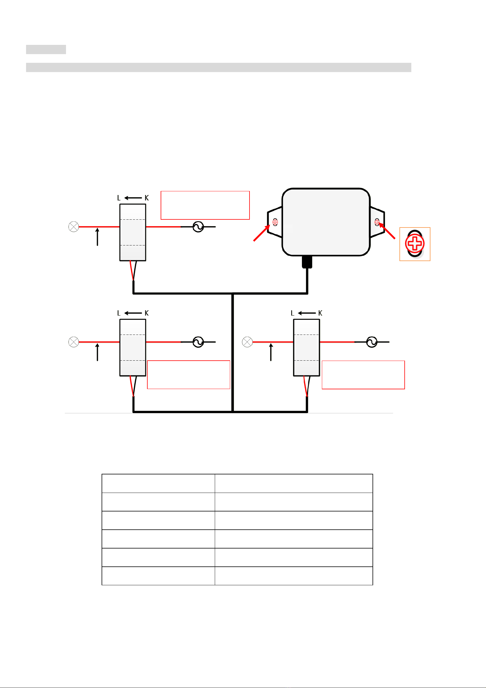
a. Connect a battery to a 68ohm resistor in parallel
b. Keep the connection for 6~8 minutes
c. The voltage of the circuit should be ≧3.3V
8. Important Maintenance Instruction
Kindly pay attention to the following in order to achieve the best maintenance of the product:
•Do not put the device near or submerge into water. Minerals in rain, moisture, and other liquids could cause corrosion of
electronic components. Please dry the device, if it gets wet.
•Do not use or store the device in dusty or dirty environments to prevent damage to parts and electronic components.
•Do not store the device in high temperatures. This may shorten the lifespan of electronic components, damage batteries, and
deform plastic parts.
•Do not store the device in cold temperatures. Moisture may damage circuit boards as the temperatures rise.
•Do not throw or cause other unnecessary shocks to the device. This may damage internal circuits and delicate components.
•Do not clean the device with strong chemicals, detergents, or strong detergents.
•Do not apply the device with paint. This may block detachable parts and cause malfunction.
•Do not dispose of batteries in fire to prevent explosion.
The instructions are applied to your device, battery, and accessories.
If any device is not working properly or has been damaged, please send it to the nearest authorized service provider for service.
Other manuals for R718N360
2
Table of contents
Other netvox Recording Equipment manuals

netvox
netvox R311CA User manual

netvox
netvox R718CT2 User manual

netvox
netvox R718IB User manual

netvox
netvox ZigBee Z103A User manual

netvox
netvox R718IA2 User manual

netvox
netvox R718IA User manual

netvox
netvox R718T User manual

netvox
netvox R718H2 User manual

netvox
netvox R718J2 User manual

netvox
netvox R718CK User manual

netvox
netvox ZigBee Z108A User manual

netvox
netvox R718KA2 User manual

netvox
netvox R718IB2 User manual

netvox
netvox R718H User manual

netvox
netvox R718J2 User manual

netvox
netvox R718J User manual

netvox
netvox R718J User manual

netvox
netvox R718H User manual

netvox
netvox R718IJK User manual

netvox
netvox R718T User manual