Jetter JXM-HMI User manual

User Manual
JXM-HMI
We automate your success.

Jetter AG
Graeterstrasse 2
71642 Ludwigsburg
Germany
Phone
Switchboard +49 7141 2550-0
Sales +49 7141 2550-531
Technical Hotline +49 7141 2550-444
E-mail
Technical Hotline [email protected]
Sales [email protected]
Translation of the original User Manual
Revision 1.11.1
Date of issue 10/23/2019
This document has been compiled by Jetter AG with due diligence, and based on the known
state of the art. Revisions and further development of our products are not automatically
mentioned in a reviewed document. Jetter AG shall not be liable for errors in form or content,
or for missing updates, as well as for damages or disadvantages resulting from such failure.

Jetter AG Table of contents
JXM-HMI User Manual iii
Table of contents
1 Introduction .....................................................................................................................................5
1.1 Information on this document .................................................................................................. 5
1.2 Typographical conventions......................................................................................................5
2 Safety ...............................................................................................................................................6
2.1 General information.................................................................................................................6
2.2 Warnings used in this document ............................................................................................. 6
2.3 Usage other than intended ...................................................................................................... 6
3 Product description ........................................................................................................................7
3.1 Features ..................................................................................................................................7
3.2 Nameplate ...............................................................................................................................7
4 Mechanical installation...................................................................................................................8
4.1 Mounting in combination with a JVM-104................................................................................8
4.1.1 Requirements for the installation location ...................................................................9
5 Technical specifications...............................................................................................................10
5.1 Dimensions............................................................................................................................10
5.2 Environmental conditions ...................................................................................................... 10
5.3 Mechanical specifications......................................................................................................10
5.4 Electrical properties...............................................................................................................11
5.5 EMC values ...........................................................................................................................11
5.6 Ports and interfaces ..............................................................................................................12
6 Electrical connection ....................................................................................................................13
6.1 Pin assignment - Power supply/CAN/ignition ........................................................................ 13
7 Programming.................................................................................................................................14
7.1 Device status.........................................................................................................................14
7.2 Setting the node ID................................................................................................................14
7.3 CAN identifier ........................................................................................................................ 14
7.4 CAN communication..............................................................................................................14
7.4.1 NMT commands ........................................................................................................14
7.4.2 Heartbeat...................................................................................................................14
7.4.3 TXPDO1 ....................................................................................................................15
7.4.4 RXPDO1....................................................................................................................15
7.4.5 SDO communication .................................................................................................15
7.5 Encoder configuration ...........................................................................................................16
7.6 System parameters ............................................................................................................... 17
7.7 Troubleshooting.....................................................................................................................17
8 Maintenance and repairs ..............................................................................................................18

Table of contents Jetter AG
iv JXM-HMI User Manual
8.1 Maintenance, repairs and disposal........................................................................................18
8.2 Storage and shipment ........................................................................................................... 18
9 Service ...........................................................................................................................................19
9.1 Customer service ..................................................................................................................19

Jetter AG Introduction | 1
JXM-HMI User Manual 5 / 22
1 Introduction
1.1 Information on this document
This document forms an integral part of the product and must be read and under-
stood prior to using it. It contains important and safety-related information for the
proper use of the product as intended.
Target groups This document is intended for specialists with appropriate qualifications.
Only competent and trained personnel are allowed to commission and operate
this device.
During the whole product life cycle, safe handling and operation of the device
must be ensured. In the case of missing or inadequate technical knowledge or
knowledge of this document any liability is excluded.
Availability of infor-
mation
Make sure this document is kept at the ready in the vicinity of the product
throughout its service life.
For information on new revisions of this document, visit the download area on our
website. This document is not subject to any updating service.
Start | Jetter - We automate your success.
For further information refer to the following information products:
■Version updates
Information about new versions of software products or of the operating sys-
tem of your controller.
■Online help of the JetSym software
Detailed description of software functions with application examples
■Application-oriented manuals
Information on file systems and communication interfaces
1.2 Typographical conventions
This manual uses different typographical effects to support you in finding and
classifying information. Below, there is an example of a step-by-step instruction:
üThis symbol indicates requirements which have to be met before executing
the following action.
►This sign or a numbering at the beginning of a paragraph marks an action in-
struction that must be executed by the user. Execute the instructions one after
the other.
ðThe target after a list of instructions indicates reactions to, or results of these
actions.
More information on this subject is available on our website.
Start | Jetter - We automate your success.
INFO “Info" provides you with useful information and practical tips about the product.
Jetter AG Safety | 2
JXM-HMI User Manual 6 / 22
2 Safety
2.1 General information
At the time of placing on the market, this product corresponds to the current state
of the art and meets the recognized safety rules.
Besides this user manual, laws and regulations in the operator's country are rele-
vant to the operation of the product. The operator is responsible for complying
with the directives mentioned below:
■Applicable legislation, rules, and regulations
■Relevant accident prevention regulations
■Accepted safety rules
■EU directives and other country-specific regulations
RoHS 2 The device conforms to the EU directive 2011/65/EU (RoHS 2).
2.2 Warnings used in this document
DANGER High risk
Indicates an imminently hazardous situation which, if not avoided, will result in
death or serious injury.
WARNING Medium risk
Indicates a potential hazardous situation which, if not avoided, could result in
death or serious injury.
CAUTION Low risk
Indicates a hazardous situation which, if not avoided, could result in minor or
moderate injury.
NOTICE Material damage
Indicates a situation which, if not avoided, could result in malfunctions or material
damage.
2.3 Usage other than intended
This device must not be used in technical systems which to a high degree have
to be fail-safe.
Machinery Directive This device is no safety-related part as per Machinery Directive 2006/42/EC, and
must, therefore, not be used for safety-relevant applications. This device is NOT
intended for the purpose of personal safety, and must, therefore, not be used to
protect persons.
Jetter AG Product description | 3
JXM-HMI User Manual 7 / 22
3 Product description
The JXM-HMI is a universal human-machine interface with three rugged push en-
coders. It is therefore ideally suited for a wide range of dosing and control appli-
cations in self-propelled machines. Thanks to its compact design, the JXM-HMI
can be flexibly mounted individually or in combination with a JetViewMobile 104,
for example, in the driver's cabin. Integrated LEDs ensure that the push encoders
are always perfectly visible.
The CANopen® communication interface lets you connect the module to common
CAN networks of self-propelled machines.
3.1 Features
■1 CAN port with terminating resistor
■Communication via CANopen® protocol
■Adjustable key illumination
■3 push encoders
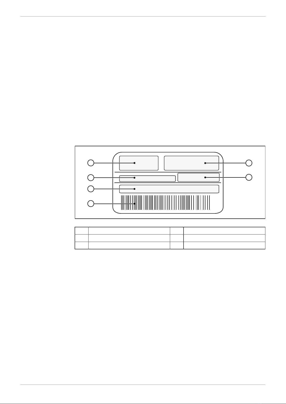
3.2 Nameplate
1
6
5
4
3
2
Fig.1: Sample nameplate
➀Logo ➁Certification mark
➂Item number ➃Barcode
➄Serial number ➅Model code number
Jetter AG Mechanical installation | 4
JXM-HMI User Manual 8 / 22
4 Mechanical installation
Mount the JXM-HMI only in a suitable place in the vehicle interior.
NOTICE Damages to material or functional impairment
Welding on the chassis may cause damages to material of the device, or impair
its functions.
● Before you start welding, disconnect all connections between the device and
the electric system of the vehicle.
● Protect the device from flying sparks and welding beads (splatter).
● Do not touch the device with the welding electrode or earth clamp.
4.1 Mounting in combination with a JVM-104
The JXM-HMI is particularly well suited for use in conjunction with the JVM-104
HMI. A special mounting plate is available for this purpose which enables both
devices to be mounted together.
Mounting Acces-
sories
Use the following accessories for installation:
Accessories Item number
Holding plate for combination of JXM-HMI and JVM-104 for
RAM Mount ball
consisting of mounting plate and screws for housing with
Deutsch or M12 connector, without RAM mount attachments
10001832
Tab.1: Mounting Accessories
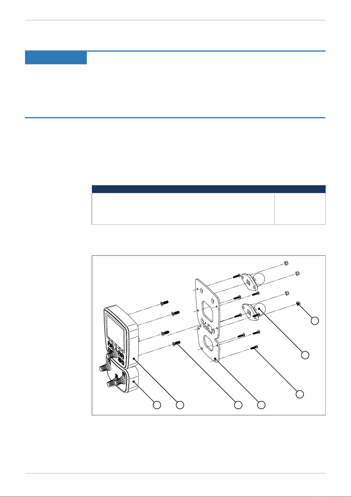
The illustration below shows how to install the device:
1 2 43
7
6
5
Fig.2: Installation drawing

Jetter AG Mechanical installation | 4
JXM-HMI User Manual 9 / 22
➀JXM-HMI ➁JVM-104
➂2 x countersunk screws for
mounting a RAM Mount ball ➃Mounting plate with opening for
connector
➄
8 x screws for fixing the mount-
ing plate to the JXM-HMI and
JVM-104
➅RAM Mount ball
➆2 x self-locking nuts
1. Screw the desired RAM Mount attachments onto the mounting plate.
2. Hold the JXM-HMI and the JVM-104 against the mounting plate from behind.
The connectors must be accessible through the openings in the mounting
plate.
3. Screw the mounting plate onto the JVM-104 and the JXM-HMI.
Installing the strain
relief
Install strain reliefs for the connecting cables.
■Ensure that there is sufficient clearance between the strain reliefs and the con-
nectors.
■Connectors must not be obstructed, so that they can be removed in the event
of service.
4.1.1 Requirements for the installation location
■The installation surface must be level.
■The installation surface should be no more than 5 mm thick.
■The installation location must allow air to circulate.
■The installation compartment must allow adequate air circulation.
■The installation location must be of sufficient size.
■The device must be easily accessible to allow for service work.
Space required for
installation and ser-
vice
It must be possible to disconnect the connectors at any time.
Avoiding unsuit-
able installation lo-
cations
The following installation locations are unsuitable for installation:
Unsuitable installation location Reason
Outdoor installation The device must not be exposed to rain
or a jet of water. Do not use a steam jet
or other such devices to clean the de-
vice.
This location is not ventilated. The JVM-104 could overheat as heat
builds up.
Installation location close to heat-sensi-
tive materials
The materials could become warped or
misshapen as a result of heat produced
by the device.
Installation surfaces are uneven. The installation surface could become
misshapen when fitting the device. Fas-
tening is unstable and precarious.
Jetter AG Technical specifications | 5
JXM-HMI User Manual 10 / 22
5 Technical specifications
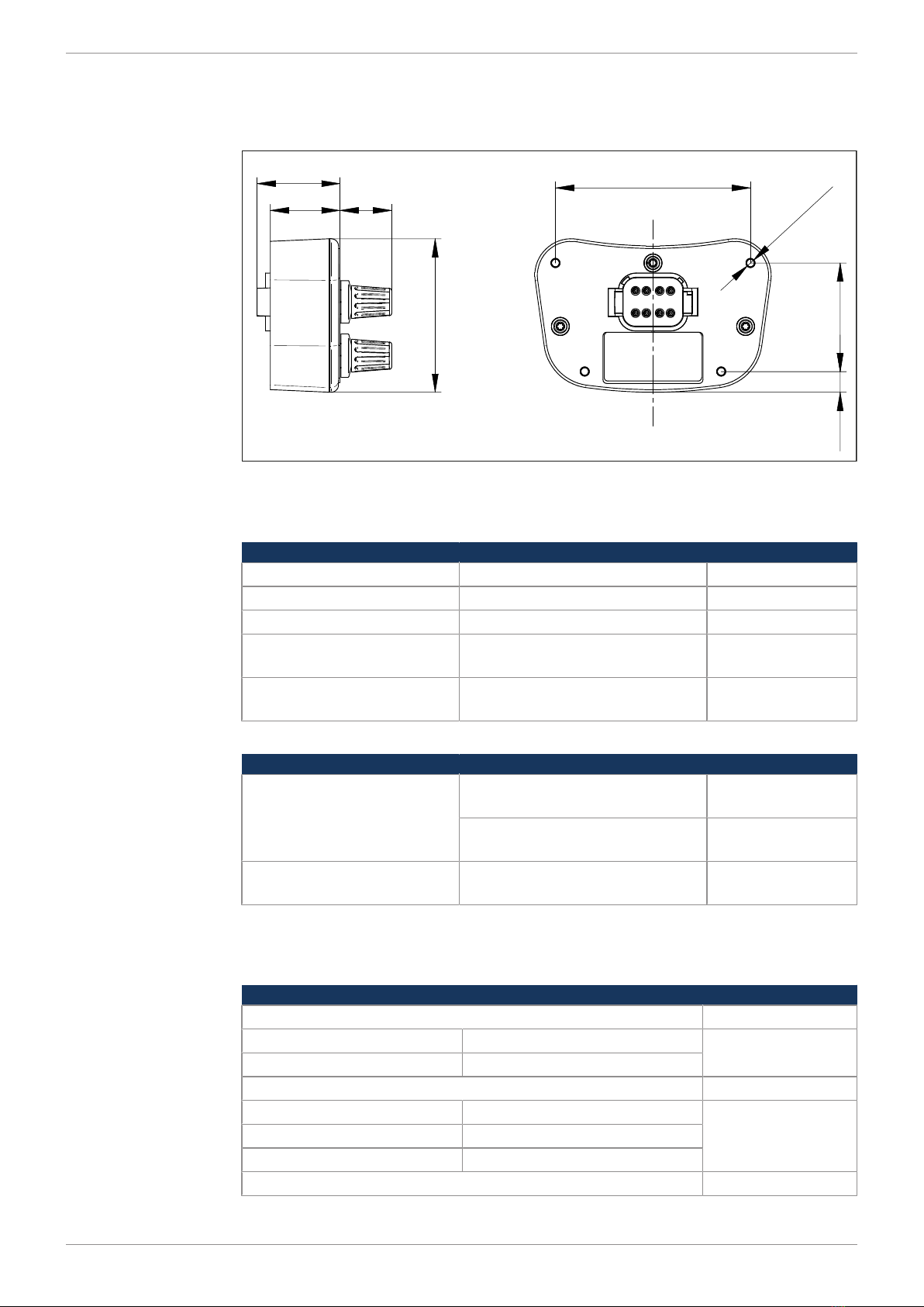
5.1 Dimensions
62.9
28.5
33.9
21.3
80
44.5
8.5
3.2
Ø
Fig.3: Dimensions (in mm)
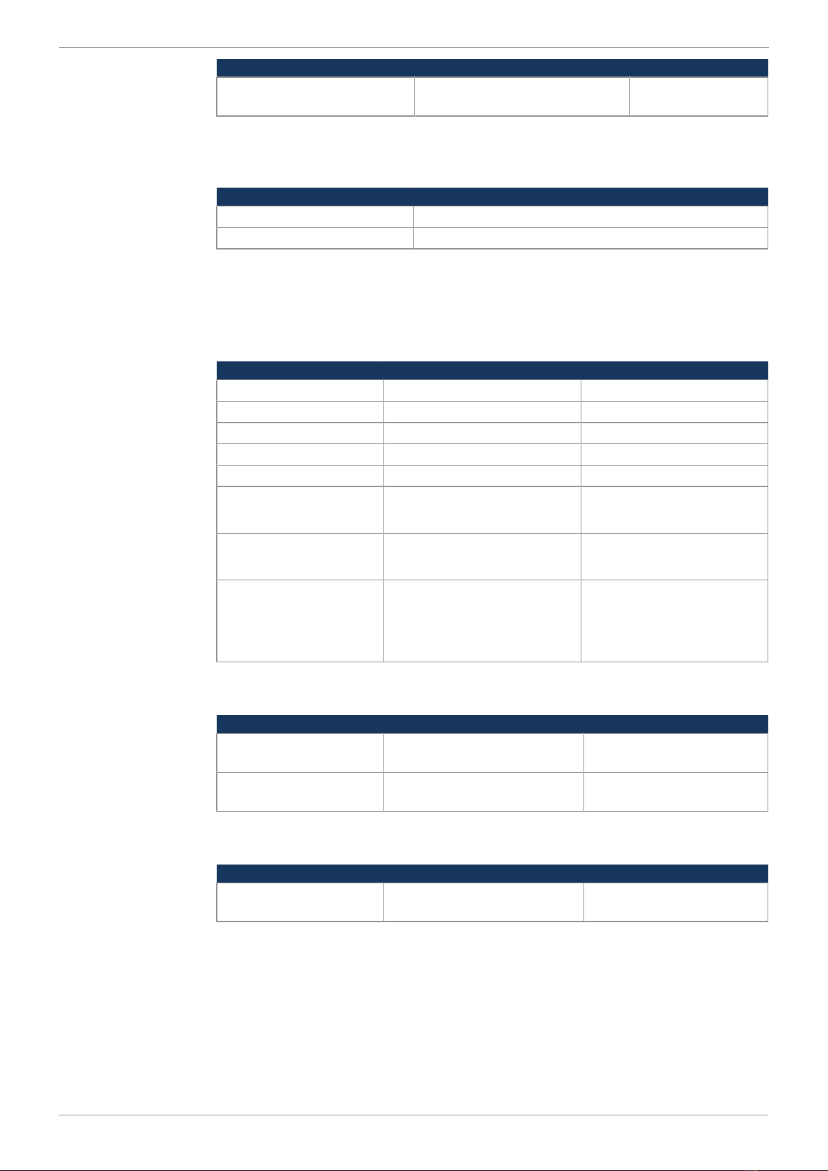
5.2 Environmental conditions
Category Description Standards
Operating temperature -30 … +85 °C
Storage temperature -30 … +85 °C
Relative humidity 5 ... 95 %
Installation location The device must be installed in
the driver's cab.
Degree of protection IP42 with mating connector
plugged in
ISO 20653:2013
Tab.2: Environmental conditions
Climatic tests Category Standards Functional class
Temperature, cyclically DIN EN 60068-2-14
(2 cycles for function test)
A
DIN EN 60068-2-14
(5 cycles for material test)
C
Humidity/temperature,
cyclically
DIN EN 60068-2-38
(-10 °C ... 55 °C)
A
Tab.3: Climatic tests
5.3 Mechanical specifications
Category Description Standards
Vibration ISO 16750-3
Floating frequency 10 … 150 Hz
Period 6 h
Shock resistance ISO 16750-3
Type of shock Half-sine wave
Intensity and duration 50 g (500 m/s²) for 18 ms
Number and direction 10 shocks in all 6 directions
Height of fall ISO 16750-3
Jetter AG Technical specifications | 5
JXM-HMI User Manual 11 / 22
Category Description Standards
Free fall 1 m onto solid ground or steel
plate
Tab.4: Mechanical specifications
5.4 Electrical properties
Category Description
Abbreviation VBAT_ECU
Operating voltage 8 … 32 V DC
Tab.5: Power Supply
5.5 EMC values
The JXM-HMI has E1 approval according to ECE R10 Rev. 5 and CE conformity
according to ISO 14982.
Pulses to ISO
7637-2
Test pulse Values Functional class
1 -450V C
2a +37V B
2b +20V C
3a -150V A
3b +150V A
4 (24 V) Ua1: -12 V / 50 ms
Ua2: -5 V / 500 ms
A
4 (12 V) Ua1: -6V / 15 ms
Ua2: -2.5 V / 1000 ms
A
5b Load dump
70V / 2Ω / 350 ms
A (as of HW revision
02.00)
E (up to HW revision
01.00)
Tab.6: Pulses to ISO 7637-2
ESD EN 61000-4-2 Category Values Functional class
Contact discharge ±4 kV (to conductive sur-
faces)
A
Discharge through air ±8 kV (to insulating sur-
faces)
A
Tab.7: ESD EN 61000-4-2
Radiated electro-
magnetic energy
ISO 11452-2 2004
and ISO 11452-4
2004
Category Values Functional class
Protection against RF
noise
20 MHz ... 2 GHz 30 V/m A
Tab.8: Irradiation to ISO 11452

Jetter AG Technical specifications | 5
JXM-HMI User Manual 12 / 22
5.6 Ports and interfaces
CAN port Category Description
Baud rate 125 kBaud ... 1 MBaud
Protocol CANopen®
Default node ID on the CANopen®
bus
0x11
Terminating resistor Integrated
Connector specifications Twisted pair conductors, unshielded
CANopen® ports 1
Protection ■Short circuit
■Overvoltage protection (32 V max.)
Tab.9: CAN port
Jetter AG Electrical connection | 6
JXM-HMI User Manual 13 / 22
6 Electrical connection
NOTICE Damages to material or functional impairment
Improper implementation of the wiring harness may cause mechanical stress.
● Protect the cables from bending, twisting or chafing.
● Install strain reliefs for the connecting cables.
NOTICE Overvoltage due to missing external fuses
High voltages can impair the functions of the device or damage the device.
● Make sure that the voltage inputs are fused according to the requirements.
● Observe the ESD principles when handling the device.
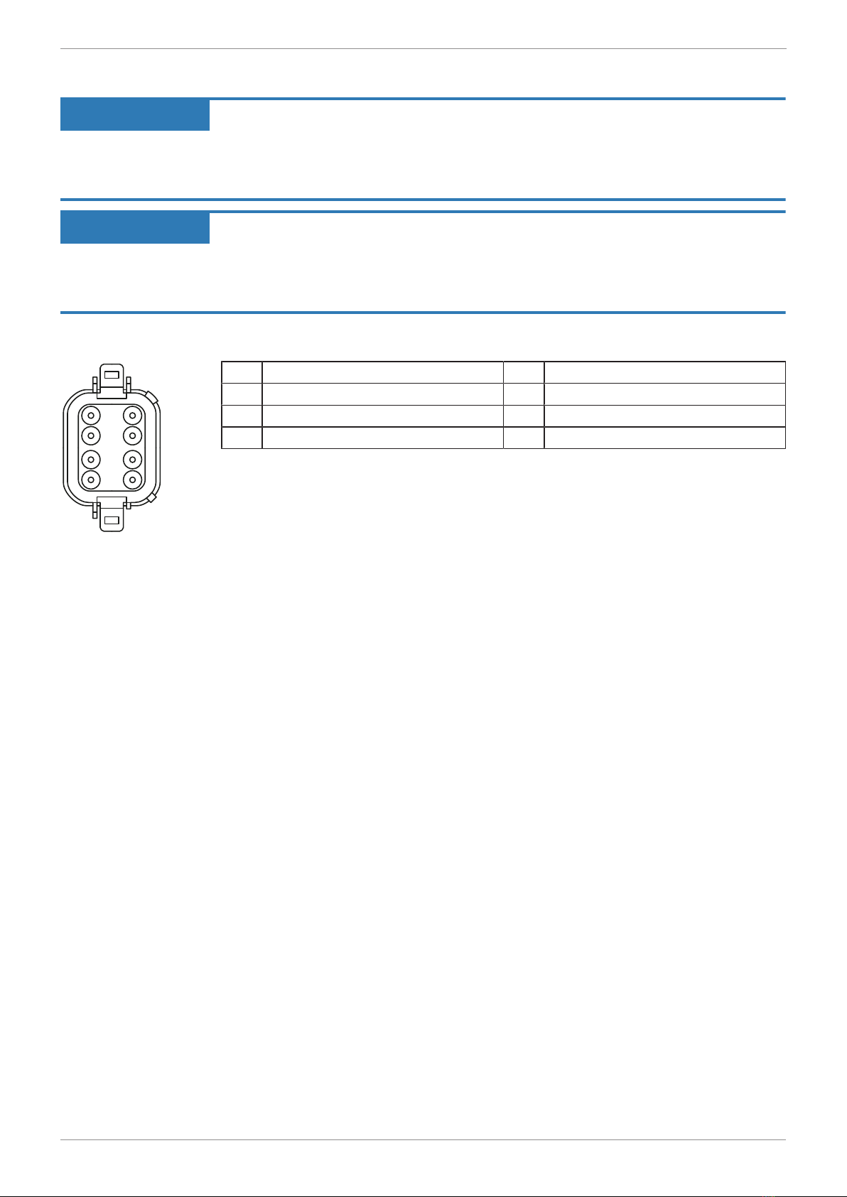
6.1 Pin assignment - Power supply/CAN/ignition
4
3
2
1
5
6
7
8
Fig.4: Deutsch connec-
tor, 8 pins
4 VBAT_ECU 5 VBAT_ECU
3 GND_IN 6 GND_OUT
2 CAN_H_IN 7 CAN_H_OUT
1 CAN_L_IN 8 CAN_L_OUT
Jetter AG Programming | 7
JXM-HMI User Manual 14 / 22
7 Programming
7.1 Device status
Status Condition Features
Bootloader PRE-OPERATIONAL
No firmware present ■Information SDOs are accessible
■Firmware update possible
■Heartbeat
OPERATIONAL
Firmware successfully started ■All SDOs are accessible
■Heartbeat
Tab.10: Device status
7.2 Setting the node ID
The default node ID of the JXM-HMI is 0x11 hexadecimal. The node ID can be
changed by SDO via the System parameters [}17].
7.3 CAN identifier
Message type Description CAN identifiers
NMT Network Management Telegram 0x000
SDO TX Service Data Object receive 0x580 + node ID
SDO RX Service Data Object send 0x600 + node ID
TXPDO1 Process Data Object send 0x180 + node ID
RXPDO1 Process Data Object receive 0x200 + node ID
EMCY Emergency message 0x80 + node ID
Error control Error Control Protocol (Heartbeat) 0x700 + node ID
Tab.11: CAN identifiers
7.4 CAN communication
7.4.1 NMT commands
The JXM-HMI changes into OPERATIONAL mode immediately after switching
on. The following NMT commands are supported:
NMT commands Description
Reset Node The node is reloaded and all settings are set to
their default values.
Tab.12: NMT commands
7.4.2 Heartbeat
The device sends a heartbeat message in a 1 s cycle. If the heartbeat is not
transmitted within 3 s, the HMI is not active.
Description Byte 0
BOOTUP CMD 0
OPERATIONAL CMD 5
PRE-OPERATIONAL CMD 127
Tab.13: Index of the heartbeat message

Jetter AG Programming | 7
JXM-HMI User Manual 15 / 22
7.4.3 TXPDO1
TXPDO1 is sent each time the encoder values change, but not more than once
per 100 ms. Encoder values are values of a free-running counter. With a positive
overflow the value changes to 0x0, with a negative overflow to 0xffff. Dynamiza-
tion can take place in the controller.
Byte 0/1 Byte 2/3 Byte 4/5 Byte 6
Uint16_t
Encoder 1 value
Uint16_t
Encoder 2 value
Uint16_t
Encoder 3 value
Encoder return:
Bit 0 = Encoder 1
Bit 1 = Encoder 2
Bit 2 = Encoder 3
Tab.14: TXPDO1
7.4.4 RXPDO1
Telegrams sent to the JXM-HMI in OPERATIONAL mode:
Description Byte 0 Byte 1 Byte 2 Byte 3/4 Byte 5 Byte 6/7
Key illumination/
LED control
(cyclic transmis-
sion)
1 Key illumi-
nation
0 … 100
%
Tab.15: RXPDO1
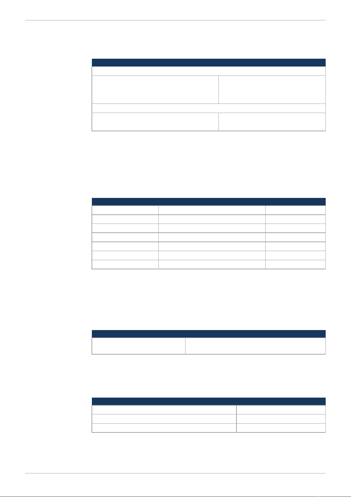
7.4.5 SDO communication
According to CANopen® the following indices can be queried:
Index Subindex Description Typ
eDir Default value
0x1000 0 Device type U32 R
0x1001 0 Error register:
Bit 0: Generic error
Bit 3: Temperature
Bit 4: Communication error
U32 R
0x1008 0 Device Name STR R
0x1009 0 Hardware revision of device STR R
0x100A 0 Software version of device STR R
0x1018 0 Number of supported en-
tries
U8 R
1 Distributor ID U32 R 0x000000B3
(Jetter's distributor
ID)
2 Product code U32 R
3 Revision number U32 R
4 Serial number U32 R
Tab.16: SDO communication

Jetter AG Programming | 7
JXM-HMI User Manual 16 / 22
7.5 Encoder configuration
Index Subindex Description Type Dir Default
value
0x2002…
0x2004
Encoder 1 ...
encoder 3
0 Number of supported en-
tries
U8 R 7
1 Bit 0 = 0
Increment direction right
Bit 0 = 1
Increment direction left
U8 R/W 0
Bit 1 = 0
Dynamization OFF
Bit 1 = 1
Dynamization ON
U8 R/W 0
Bit 2 = 0
Limit values OFF
Bit 2 = 1
Limit values ON
U8 R/W 0
2 Rotary pulse/second up to
level 1
U16 R/W 4
3 Level 1 step size U16 R/W 10
4 Rotary pulse/second up to
level 2
U16 R/W 7
5 Level 2 step size U16 R/W 100
6 Rotary pulse/second up to
level 3
U16 R/W 10
7 Level 3 step size U16 R/W 1000
8 Minimum value U16 R/W 0
9 Max. value U16 R/W 0
10 Value/encoder output
(analog to TXPDO1 [}15])
U16 R/W 0
Tab.17: Encoder configuration
Jetter AG Programming | 7
JXM-HMI User Manual 17 / 22
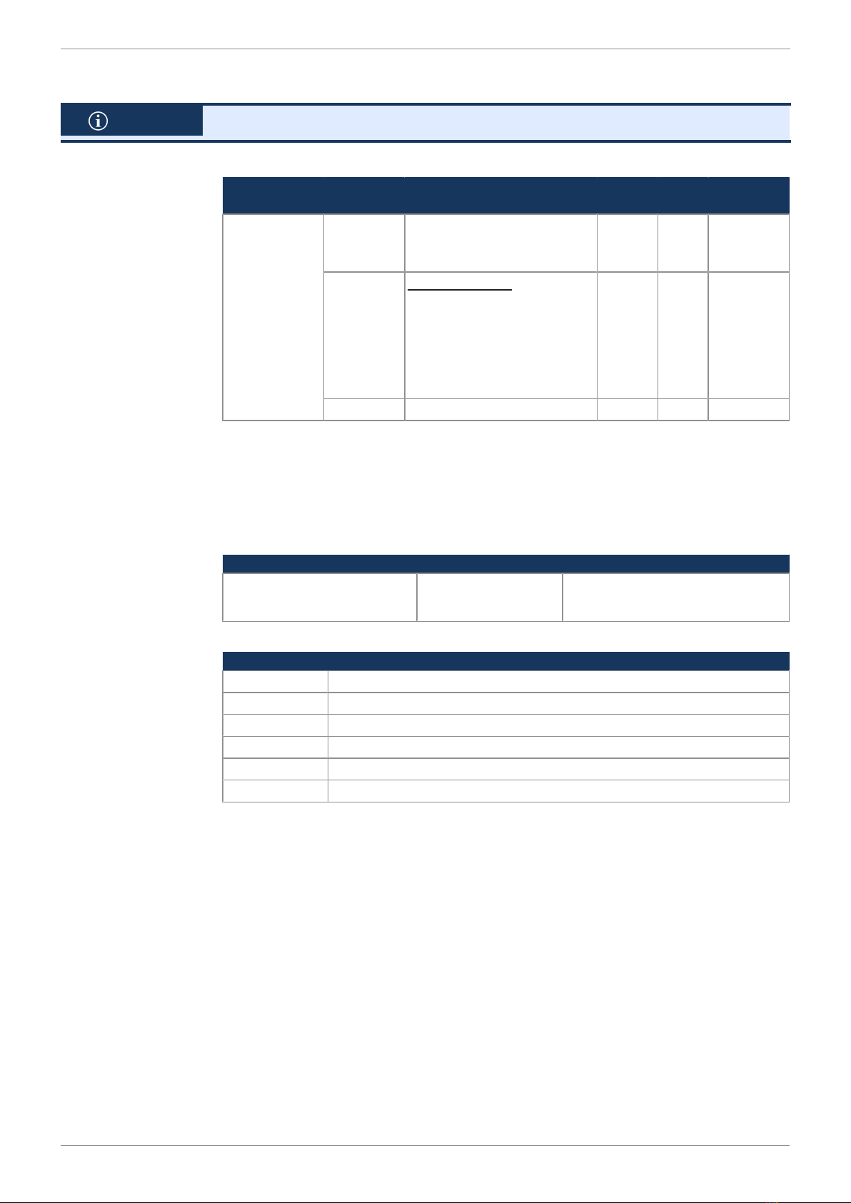
7.6 System parameters
INFO You can only use the set system parameters after restarting the system.
Index Subindex Description Type Dir Default
value
0x4556 0 Number of supported en-
tries
U8 R 4
3 CAN baud rate:
3 = 1 MBaud
2 = 500 kBaud
1 = 250 kBaud
0 = 125 kBaud
U8 R/W 1
4 CANopen® node ID U8 R/W 0x11
Tab.18: System parameters
7.7 Troubleshooting
EMCY telegrams are sent at startup or after any changes at an inhibit time of 50
ms (minimum pause between 2 telegrams). An EMCY telegram is sent when an
event is started or changed.
Emergency object
telegrams (EMCY
telegrams)
Byte 0/1 Byte 2 Byte 3-7
Emergency Error Code Error register
Object 0x1001
Manufacturer specific error field
Always 0 is sent.
Tab.19: Bit values of emergency objects
Error memory (er-
ror history)
Code Description
0x0000 No error or error reset
0x1000 Generic error
0x3100 Voltage VBAT_ECU exceeds the permitted limits
0x4200 Device temperature is too high
0x8110 CAN data overrun (lost objects)
0x8140 Recovered from bus-off
Tab.20: Emergency Error Codes

Jetter AG Maintenance and repairs | 8
JXM-HMI User Manual 18 / 22
8 Maintenance and repairs
8.1 Maintenance, repairs and disposal
Maintenance This device is maintenance-free.
Therefore, for the operation of the device no inspection or maintenance are re-
quired.
Repairs Defective components could cause dangerous malfunctions and could compro-
mise safety.
Only the manufacturer is allowed to repair the device.
Do not open the device!
Disposal of obso-
lete equipment
The device must be disposed of in accordance with the Environmental Product
Declaration EPD. Applicable local environmental directives and regulations must
be complied with. This product must be disposed of as waste electronic equip-
ment. Waste packaging material must be recycled or reused.
Modifications and
alterations to the
device
Modifications and alterations to the device and its functions are not allowed. In
the case of modifications to the device, any liability is excluded.
The original parts are specifically designed for the device. Parts and equipment
from other manufacturers must, therefore, not be used.
Any liability for any damages resulting from the use of non-original parts and
equipment is excluded.
8.2 Storage and shipment
Storage When storing the device observe the environmental conditions given in chapter
“Technical specifications”.
Shipment and pack-
aging
The device contains electrostatically sensitive components which can be dam-
aged if not handled properly. Damages to the device may impair its reliability.
To protect the device from impact or shock, it must be shipped in its original
packaging, or in an appropriate protective ESD packaging.
In case of damaged packaging inspect the device for any visible damage, and in-
form your freight forwarder and the Jetter AG of the damage caused during ship-
ment. If the device is damaged or has been dropped, it is strictly forbidden to use
it.

Jetter AG Service | 9
JXM-HMI User Manual 19 / 22
9 Service
9.1 Customer service
Should you have any questions, suggestions, or problems, please don’t hesitate
to contact our service representatives. To contact them, please call our technical
hotline or use the contact form on our homepage:
Technical hotline | Jetter - We automate your success.
You are also welcome to send an e-mail to our technical hotline:
Please supply the following information when contacting our technical hotline:
■Hardware revision and serial number
For the hardware revision number, please refer to the nameplate.

Jetter AG List of figures
JXM-HMI User Manual 20 / 22
List of figures
Fig. 1 Sample nameplate .................................................................................................................. 7
Fig. 2 Installation drawing.................................................................................................................. 8
Fig. 3 Dimensions (in mm) ................................................................................................................ 10
Fig. 4 Deutsch connector, 8 pins....................................................................................................... 13
This manual suits for next models
1
Table of contents
Other Jetter Recording Equipment manuals


