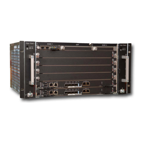
Integral Technologies DVXi TS4 User manual

Information in this document is subject to change without notice.
© Copyright 2003, Integral Technologies. All rights reserved.
MasterControl and Integral Technologies are trademarks of Integral Technologies. Other trademarks
and trade names may be used in this document to refer to either the entities claiming the marks or
names or their products. Integral Technologies disclaims any proprietary interest in trademarks and
trade names other than its own.
Integral Technologies makes no warranty of any kind with regard to this material, including, but not
limited to, the implied warranties of merchantability and fitness for a particular purpose. Integral
Technologies shall not be liable for errors contained herein or for incidental or consequential
damages in connection with the furnishing, performance, or use of this manual.
Integral Technologies
9855 Crosspoint Blvd., Suite 126
Indianapolis, Indiana 46256 U.S.A.
User Manual
DVXi 4.0
April 2003
#3000-40060 Rev. 1

(continued)
TABLE OF CONTENTS
Introduction......................................................................................... 1
About the DVXi Series ..........................................................................................2
What This Manual Covers .....................................................................................3
Precautions...........................................................................................................4
Installation........................................................................................... 5
Installing DVXi TS4 and DVXi TBC4......................................................................6
Installing DVXi TS9 D and DVXi TBC9 D...............................................................8
Installing DVXi TS9 RM/TS16 and DVXi TBC9 RM/TBC16.................................. 10
Installing DVXi XM16 and DVXi XM32.................................................................12
Installing XMUX .................................................................................................. 14
Running the MasterControl Application................................................................ 16
Accessing the MasterControl Database...............................................................17
Changing the SQL Server Password ...................................................................18
Getting Familiar with MasterControl ............................................... 19
Overview of the MasterControl Screen ................................................................ 20
The Function Buttons..........................................................................................21
The Status Bar.................................................................................................... 22
MasterControl Configuration........................................................... 23
About the Setup Page .........................................................................................24
Adjusting the Video Display................................................................................. 25
Configuring Hardware .........................................................................................26
Naming Cameras ................................................................................................29
Configuring Disk Usage....................................................................................... 30
Defining MasterControl Users..............................................................................31
Configuring Motion Detection .............................................................................. 37
Understanding Motion Detection .........................................................................38
Assigning Cameras to Alarms .............................................................................42
Video Outputs and Touring .................................................................................45
Configuring Multi-Camera Output ........................................................................ 47
Configuring Onscreen Display on Video Outputs .................................................48
Archiving.............................................................................................................50
Configuring PTZ Cameras................................................................................... 56
MtCtlO ti 59

MasterControl Operation ................................................................. 59
Viewing Live Video on the Monitor Page .............................................................60
Selecting Recording Modes................................................................................. 66
Setting a Recording Schedule ............................................................................. 67
Searching for Recorded Video ............................................................................ 78
Viewing Recorded Video..................................................................................... 83
Exporting Captured Images and Video ................................................................84
Viewing Disk Usage ............................................................................................85
RemoteView ...................................................................................... 87
Introduction to RemoteView ................................................................................ 88
Connecting the Client and Server........................................................................ 89
Installing the RemoteView Software .................................................................... 89
Configuring a Dial-up Connection........................................................................ 90
Running the RemoteView Software ..................................................................... 93
Important Information About Passwords .............................................................. 94
Overview of the RemoteView Screen ..................................................................95
The Servers Page ...............................................................................................96
The Monitor Page ...............................................................................................98
The Search Page.............................................................................................. 104
The Setup Page ................................................................................................ 109
How RemoteView Admin Changes are Applied ................................................. 109
The Alarms Page .............................................................................................. 112
The Schedule Page........................................................................................... 113
RemoteView Server Settings............................................................................. 114
Appendix A: DVXi Plug-ins ............................................................ 115
Introduction to Plug-ins...................................................................................... 116
DVXMonitor Plug-in .......................................................................................... 117
MotionAlarm Plug-in.......................................................................................... 120
DVXNotify Plug-in ............................................................................................. 123
Appendix B: Synchronizing DVXi Clocks..................................... 129
Appendix C: Technical Support and Warranty Information........ 131

Introduction
Thank you for purchasing a DVXi digital event recorder, a high-tech moni-
toring and recording solution to cover all your security needs.
This chapter introduces you to your DVXi system and the structure of this
manual. Included in this chapter are the following:
•A description of the main parts of your DVXi system
•An outline of the chapters of this manual
Again, thank you for choosing a DVXi digital event recorder for your high-
tech security needs.

2
ABOUT THE DVXi SERIES
The DVXi digital event recorder is a high-tech monitoring and recording solution
that covers all your security needs. The following products are the heart of the
DVXi package:
•The DVXiTM box captures and compresses video for digital display from
up to 16 cameras for safe storage and easy access.
•MasterControlTM is the user-friendly software that allows you to easily
monitor and record video from multiple cameras. The simple configura-
tion instructions in this manual can help you set up MasterControl for
unattended recording for extended periods.
•Installed with XMUX (included with DVXi XM16 and DVXi XM32),
the DVXi system expands to as many as 32 video inputs.
•RemoteViewTM is an application that allows you to download and view
live and recorded video from DVXi over a network or dial-up connec-
tion. You can also connect to and even configure multiple DVXi systems
remotely.
•The DVXMonitor (optional), MotionAlarm, and DVXNotify plug-ins
are standalone applications that expand the reach of DVXi by recovering
from a system failure or communicating messages externally from the
system.
•XPVPlayer allows you to play back XPV files exported from the DVXi
system on a separate PC.

3
Introduction
WHAT THIS MANUAL COVERS
This manual takes you through the following topics, complete with illustrations,
step-by-step instructions, and detailed descriptions:
•Installation—includes instructions for installing the DVXi system and
running MasterControl for the first time.
•Getting Familiar with MasterControl—describes the basic setup of the
MasterControl screen. It also offers brief descriptions of each of the
MasterControl functions.
•MasterControl Configuration—helps you set up MasterControl for
everyday use. For example, it includes information on setting up user
permissions, naming cameras, and configuring hardware to your desired
performance level.
•MasterControl Operation—explains the primary functions of
MasterControl. From viewing and capturing video to learning the impor-
tant scheduling feature, this chapter shows you how to actually operate
MasterControl for your daily security needs.
•RemoteView—describes the RemoteView software, including details
about downloading live and recorded video from a remote client PC.
•Appendix A: DVXi Plug-ins—describes the standard and optional
standalone applications available on a DVXi system.
•Appendix B: Synchronizing DVXi Clocks—describes a procedure that
allows you to synchronize the Windows time of multiple DVXi systems
to a master source on a network.
•Appendix C: Technical Support and Warranty Information
If you require further assistance with your DVXi system than this manual offers,
please refer to the technical support information available in Appendix C.

4
LITHIUM BATTERY—DANGER
The battery should be replaced only by a service technician. The
battery is a non-operator-replaceable cell. There is danger of explo-
sion if the battery is incorrectly replaced. Replace only with the same
or equivalent type recommended by the manufacturer. Dispose of
used batteries according to the manufacturer’s instructions.
Caution
RISK OF ELECTRIC SHOCK—DO NOT OPEN
To reduce risk of electric shock, do not remove the cover or back of
the DVXi system. There are no user-serviceable parts inside. Refer
servicing to qualified personnel only.
Caution
PRECAUTIONS

Installation
The installation of your DVXi system consists of connecting the box to its
peripheral equipment (monitor, mouse, and so on) and XMUX (DVXi XM16
and DVXi XM32 only). This chapter contains specific instructions for the
following:
•Installing DVXi TS4 and DVXi TBC4
•Installing DVXi TS9 D and DVXi TBC9 D
•Installing DVXi TS9 RM/TS 16 and DVXi TBC9 RM/TBC16
•Installing DVXi XM16 and DVXi XM32
•Installing XMUX
•Running the MasterControl application for the first time
•Accessing the MasterControl database and changing the SQL
password
Please pay special attention to the cautions and tips throughout the chapter.

6
INSTALLING DVXi TS4 and DVXi TBC4
Use Figure 1 to complete the following installation instructions.
1. Plug the power cord into the power connector (A).
2. Plug the mouse into the mouse connector (B).
3. Plug the keyboard into the keyboard connector (C).
4. To provide a network or dial-up connection, connect a network cable to
the network connector (D) or a phone line to the optional modem (H).
5. Plug the monitor into the monitor connector (E) and electrical outlet.
6. (Optional) Wire the alarms to the green trigger block (F). From top to
bottom are board inputs 1–8, an output, and three grounds. On the
MasterControl Alarms tab, the inputs are named Board Alarm 1, Board
Alarm 2, and so on. Connect only to voltages below 42V DC; external
devices connected to the DVXi system should be in a SELV, non-energy
hazardous circuit.
7. Connect up to four cameras to the row of BNC connectors (G). Inputs are
labeled 1 through 4 from bottom to top.
8. (Optional) Connect your PTZ cameras to the RS-422 port (J) as described
in the PTZ installation manual.
9. Plug the power cord into an electrical outlet.
10. To provide power to the DVXi box, use the power switch on the rear
panel (K).
11. To turn on the DVXi system, use the power switches on the front panel of
the box and on the monitor.

7
Installation
Figure 1
The rear panel of DVXi 4-camera systems. The placement of system components may
vary depending on which options are installed.
KABCE GD
REAR PANEL OF DVXi TS4 and DVXi TBC4
HJ
F

8
INSTALLING DVXi TS9 D and DVXi TBC9 D
Use Figure 2 to complete the following installation instructions.
1. Plug the power cord into the power connector (A).
2. Plug the mouse into the mouse connector (B).
3. Plug the keyboard into the keyboard connector (C).
4. To provide a network or dial-up connection, connect a network cable to
the network connector (D) or a phone line to the optional modem (J).
5. Plug the monitor into the monitor connector (E) and electrical outlet.
6. (Optional) Wire the alarms to the green trigger block (F). From top to
bottom are board inputs 1–16, an output, and a ground. On the
MasterControl Alarms tab, the inputs are named Board Alarm 1, Board
Alarm 2, and so on. Connect only to voltages below 42V DC; external
devices connected to the DVXi system should be in a SELV, non-energy
hazardous circuit.
7. Connect up to five cameras to the first (left) row of BNC connectors (G).
These inputs are labeled 1 through 5 from bottom to top.
8. Connect up to four cameras to the second (right) row of BNC connectors
(H). These inputs are labeled 6 through 9 from bottom to top. For video
output, connect a VCR or external TV/monitor to the connector labeled
OUTPUT (top).
9. (Optional) Connect your PTZ cameras to the RS-422 port (K) as described
in the PTZ installation manual.
10. Plug the power cord into an electrical outlet.
11. To provide power to the DVXi box, use the power switch on the rear
panel (L).
12. To turn on the DVXi system, use the power switches on the front panel of
the box and on the monitor.

9
Installation
Figure 2
The rear panel of DVXi 9-camera systems (desktop chassis). The placement of system
components may vary depending on which options are installed.
BC E HDF
REAR PANEL OF DVXi TS9 D and DVXi TBC9 D
GK
LA J

10
Use Figure 3 to complete the following installation instructions.
1. Plug the power cord into the power connector (A).
2. Plug the mouse into the mouse connector (B).
3. Plug the keyboard into the keyboard connector (C).
4. To provide a network or dial-up connection, connect a network cable to
the network connector (D) or a phone line to the optional modem (H).
5. Plug the monitor into the monitor connector (E) and electrical outlet.
6. Connect up to nine (DVXi TS9 or TBC9 systems) or up to sixteen cam-
eras (DVXi TS16 or TBC 16 systems) to the row of BNC connectors (F).
For video output, connect a VCR or external TV/monitor to the connec-
tor labeled OUTPUT.
7. (Optional) Wire the alarms to the green trigger block (G). From top to
bottom are board inputs 1–16, an output, and a ground. On the
MasterControl Alarms tab, the inputs are named Board Alarm 1, Board
Alarm 2, and so on. Connect only to voltages below 42V DC; external
devices connected to the DVXi system should be in a SELV, non-energy
hazardous circuit.
8. (Optional) Connect your PTZ cameras to the RS-422 port (J) as described
in the PTZ installation manual.
9. Plug the power cord into an electrical outlet.
10. To provide power to the DVXi box, use the power switch on the rear
panel (K).
11. To turn on the DVXi system, use the power switches on the front panel of
the box and on the monitor.
See “Installing DVXi XM16 and DVXi XM32” for important
rack-mount installation considerations.
Caution
INSTALLING DVXi TS9 RM/TS16 and DVXi TBC9 RM/TBC16

11
Installation
Figure 3
The rear panels of DVXi 9- and 16-camera systems (rack-mount chassis). The place-
ment of system components may vary depending on which options are installed.
REAR PANEL OF DVXi TS9 RM and DVXi TBC9 RM
ABCE JDK
F
INPUT 1 INPUT 2 INPUT 3 INPUT 4 INPUT 5 INPUT 6 INPUT 7 INPU T 8 INPU T 9 O UTPU T
G H
REAR PANEL OF DVXi TS16 and DVXi TBC16
ABCK
F
INPUT1INPUT2INPUT3INPUT4INPUT5INPUT6INPUT7INPUT8INP U T 9 INP U T 10 IN PU T 1 1 IN PU T 1 2 IN PU T 13 IN PU T 1 4 INPU T 1 5 IN PU T 1 6 O U TP UT
EJD HG

12
INSTALLING DVXi XM16 and DVXi XM32
Use Figure 4 to complete the following installation instructions.
1. Plug the power cord into the power connector (A).
2. Plug the mouse into the mouse connector (B).
3. Plug the keyboard into the keyboard connector (C).
4. To provide a network or dial-up connection, connect a network cable to
the network connector (D) or a phone line to the optional modem (G).
5. Plug the monitor into the monitor connector (E) and electrical outlet.
6. Plug the XMUX Cable into the DB-25 connector (F).
7. (Optional) Connect your PTZ cameras to the RS-422 port (H) as described
in the PTZ installation manual.
8. Plug the power cord into an electrical outlet.
9. To provide power to the DVXi box, use the power switch on the rear
panel (J).
10. To turn on the DVXi system, use the power switches on the front panel of
the box and on the monitor.
11. Proceed to the “Installing XMUX” section.

13
Installation
Figure 4
The rear panel of DVXi XM 16- and 32-camera systems. The placement of system
components may vary depending on which options are installed.
RACK-MOUNT INSTALLATION CONSIDERATIONS
Elevated Operating Ambient. If installed in a closed or multi-unit rack assembly, the oper-
ating ambient temperature of the rack environment may be greater than room ambient. There-
fore, consideration should be given to installing the equipment in an environment compat-
ible with the manufacturer’s maximum rated ambient temperature of 32ºC.
Reduced Air Flow. Installation of the equipment in a rack should be such that the amount of
air flow required for safe operation of the equipment is not compromised.
Mechanical Loading. Mounting of the equipment in the rack should be such that a hazard-
ous condition is not achieved due to uneven mechanical loading.
Circuit Overloading. Consideration should be given to the connection of the equipment to
the supply circuit and the effect that overloading of the circuits might have on overcurrent
protection and supply wiring. Appropriate consideration of equipment nameplate ratings should
be used when addressing this concern.
Reliable Earthing. Reliable earthing of rack-mounted equipment should be maintained. Par-
ticular attention should be given to supply connections other than direct connections to the
branch circuit (e.g. use of power strips).
REAR PANEL OF DVXi XM16 and DVXi XM32
A CB E FJ D GH

14
INSTALLING XMUX (DVXi XM16 and DVXi XM32 ONLY)
XMUX is a 16- or 32-input digital video multiplexer. When used with DVXi XM16
or DVXi XM32, XMUX delivers 60 unique images of video every second to the
DVXi system, which digitizes and stores the images.
To install XMUX, complete the following steps using Figure 5 as a guide:
1. Make sure the 25-pin connector of the XMUX Cable (F) is connected to
the DB-25 connector on the DVXi box, as described in the DVXi XM16
and DVXi XM32 installation instructions.
2. Connect your cameras to the video input connectors (A).
3. DVXi XM16 systems only: Connect the camera loop-through outputs
(B) to television monitors, VCRs, or other analog devices, if desired.
Output 1 loops video from input 1, output 2 from input 2, and so on.
4. Connect Aux1–Aux4 (C) to television monitors, VCRs, or other analog
devices, if desired.
5. (Optional) Wire any alarm triggers into the input portion of the trigger
block (D). Connect the signal ground to the GND pin. Wire an alarm
signal to the output portion of the trigger block (NO, C, and NC) so that
you can see when a designated alarm is set or tripped.
6. Connect the 15-pin connector of the XMUX Cable (G) to Comm In (E).
XMUX is powered by the DVXi system; there is no power switch on XMUX.

15
Installation
Figure 5
The XMUX cable connects DVXi XM16 and DVXi XM32 systems
to the back panel of XMUX-16 and XMUX-32, respectively.
C
A
D E
REAR PANEL OF XMUX-16
In
Aux2
Aux3
Alarm In
p
uts
N
0
C
N
C
G
N
D
Out
p
uts
Aux4
Aux115432 6 7 8 9 10111213141516
Out
1
2
3
4
5
6
7
8
9
10
11
12
13
14
15
16
C
B
I/O Port
AREAR PANEL OF XMUX-32
In
19753 1113151719212325272931
In
2 4 6 8 101214161820222426283032
A
B
C D
Aux2
Aux3
Alarm In
p
uts
N
0
C
N
C
G
N
D
Out
p
uts
Aux4
Aux1
1
2
3
4
5
6
7
8
9
10
11
12
13
14
15
16
B
I/O Port
XMUX Cable
INTEGRAL
F G

16
Figure 6
After you enter
a valid ID
and password,
MasterControl
scans for con-
nected cameras.
Your DVXi system has some of the same capabilities as a regular
personal computer. However, it is recommended that you do not use
your DVXi system for anything other than operating the
MasterControl software. Wandering to other parts of the system could
damage DVXi’s intended functionality—so do this only at your own
risk. See the “Security Features” section of the “MasterControl Con-
figuration” chapter for more information.
Caution
Tip
Be sure to change your DVXi user ID and password immediately.
See the “Defining MasterControl Users” section of the “MasterControl
Configuration” chapter for information on how to do this. The de-
fault administrator password is “letmein” for both Windows and
MasterControl.
RUNNING THE MASTERCONTROL APPLICATION
When you turn on the DVXi system for the first time, MasterControl automati-
cally runs (you can also manually run the application from Start, Programs, and
MasterControl). When you see the Enter Password window, enter “administrator”
for User and “letmein” for Password. MasterControl then scans for connected cam-
eras (see Figure 6) and opens up to the Monitor page. Now you are ready to con-
figure MasterControl for daily use.

17
Installation
ACCESSING THE MASTERCONTROL DATABASE
Only Windows users with Administrator permissions can operate MasterControl
initially; all other users see an error when they try to start the application. How-
ever, Windows users without Administrator permissions can be added manually
to the list of valid MasterControl users. To grant a non-Administrator Windows
user access to the MasterControl database, complete the following steps while
logged on to Windows with Administrator permissions:
1. From the C:\Program Files\Integral\MasterControl directory, run
ManageMCDB.EXE.
2. Click Next twice to view the Administrator tab (see Figure 7).
3. Under Authorized Accounts, double-click the Windows users that should
have permission to run MasterControl. Users listed with green checks are
authorized to run MasterContol, whereas users listed with a red “X” are
not authorized. Close Manage MCDB when finished.
If you demote the default “DVX1” account to a non-administrator status in Win-
dows, be sure to authorize it using Manage MCDB.
Figure 7
Manage MCDB
allows you to
access the
MasterControl
database.
This manual suits for next models
7
Table of contents
Other Integral Technologies Network Hardware manuals
