network MOT-BOX User manual

MOT-BOX
Hard-shell case for one flashlink®2U frame
Product Manual
Rev. 0

MOT-BOX Rev. 0
Network Electronics ASA
Thorøya
P.O. Box 1020
Sandefjord, Norway
Phone: +47 33 48 99 99
Fax: +47 33 48 99 98
E-mail: [email protected]
www.network-electronics.com
Service Phone: +47 90 60 99 99
Revision history
Current revision of this document is the uppermost in the table below.
Revision Replaces Date Change description
0 A 13/07/05 No changes; first official release.
A - 09/06/05 NBS: Initial Revision.
2

MOT-BOX Rev. 0
Contents
Revision history............................................................................... 2
1 Product overview......................................................................... 4
1.1 Features:......................................................................................................4
2 Specifications .............................................................................. 5
2.1 General specifications ..................................................................................5
2.2 Front view ...................................................................................................5
2.3 Rear view.....................................................................................................5
3 Connections ................................................................................ 7
3.1 Service connections .....................................................................................7
3.2 Module connections....................................................................................8
3.2.1 MB-BP-01 8
3.2.2 MB-BP-02 9
3.2.3 MB-BP-03 9
3.2.4 MB-BP-04 10
3.2.5 MB-BP-05 10
3.2.6 MB-BP-06 11
3.2.7 MB-BP-07 11
3.2.8 MB-BP-08 12
3.2.9 MB-BP-09 12
3.3 MB-FR-1RU ................................................................................................13
3.4 Frame reconfiguration ...............................................................................14
4 MOT-BOX safety precautions..................................................... 15
5 Laser safety precautions ............................................................. 16
General environmental requirements for flashlink®equipment ...... 17
Certificate of Conformity .............................................................. 18
Product Warranty ......................................................................... 19
3

MOT-BOX Rev. 0
1Product overview
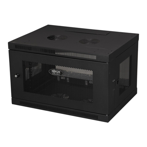
MOT-BOX is a lightweight mobile transport enclosure for the flashlink®range
of products.
MOT-BOX houses all flashlink®optical transport, signal processing and
distribution cards including WDM/CWDM. Its rugged design and connector
panel, including an expanded beam hermaphroditic fiber connector, makes it
the ideal choice for all mobile and outside broadcast applications.
Options include a fiber reel with MIL specified tactile fiber, AC and DC power
supplies, and a monitoring/alarming function via Network’s GYDA controller.
1.1 Features:
-Lightweight 3RU Mobile Transport Enclosure.
-Full set of flashlink optical, signal processing and distribution cards
including WDM/CWDM.
-Expanded beam hermaphroditic fiber connector.
-Fiber reel with MIL specified tactile fiber (option).
-AC and DC power supply option.
-Rugged connector panel and enclosure design for tough mobile use
(audio on XLR-breakouts).
-Monitoring/Alarming via GYDA controller (option).
4

MOT-BOX Rev. 0
2Specifications
2.1 General specifications
AC Power: PWR-AC15/15/5/5V
AC power supply module 100-260 VAC.
DC Power (optional): PWR-DC15/15/5/5V
DC power supply module 36-72 VDC.
Dimensions: WxDxH with front- and rear cover: 530 x 570 x 215 mm,
Without front- and rear cover: 530 x 425 x 215 mm.
Weight: Including PSU and 10 modules: <12 kg.
Card slots: 10.
Power Supply slots: 2.
Internal voltages: +5V, -5V, +15V, -15V.
2.2 Front view
The front view of the MOT-BOX (with front cover removed) shows the status
LEDs for each module that is included box + two green LEDs for the power
supply modules.
Figure 1: LEDs in front of the flashlink frame.
The uppermost LED of each module card is a "general status" LED.
-Green light means that the card is OK.
-Red light means that the card is faulty.
-No light means that the power is not switched on.
The meaning of each LED on the module cards is described in their respective
User Manuals.
2.3 Rear view
Figure 2 shows an example of a fully equipped MOT-BOX, seen from the rear
side (with rear cover removed).
To the left is the connector module for the power supply delivered with the
MOT-BOX. The other connector modules are described in Chapter 3.2.
5

MOT-BOX Rev. 0
Figure 2: Example of fully equipped MOT-BOX.
6

MOT-BOX Rev. 0
3Connections
3.1 Service connections
The figure below shows the power connections, Ethernet connections and the
expanded beam hermaphroditic fiber connector of the frame.
Figure 3: Connector module for the power supply.
AC: Connect with a mains cord with an IEC 320 connector to the MOT-BOX.
DC: Connect with a 4-pin XLR (female) from the external DC power supply to
the Neutrik NC4MD-L-1 4-pin XLR (male) receptacle of the MOT-BOX.
The following pin-out is applicable:
Pin #1 Negative part of 48VDC supply Input
Pin #2 Not in use
Pin #3 Not in use
Pin #4 Positive part of 48VDC supply Input
A green LED will light on the front when the power supply (AC or DC) is in
operation.
Ethernet: Connect with an RJ-45 plug to the Neutrik NE8FDV-YK receptacle of
the MOT-BOX.
Fiber: Connect your fiber cable with a Stratos HXMA 4-channel plug to the
Stratos HXMA 4-channel expanded beam hermaphroditic fiber receptable of
the MOT-BOX. You may connect the other end of the fiber cable to the
dedicated 1RU frame, MB-FR-1RU. See Chapter 3.3 for more information.
7

MOT-BOX Rev. 0
3.2 Module connections
The connector/receptacle layout on the rear of the MOT-BOX is depending on
the models that are included in the box/frame.
The following options are available:
Backplane Associated module(s)
MB-BP-00 Blindplate, no module associated.
MB-BP-01 ADC-AES
MB-BP-02 DAC-AES, DA-AA or DA-AES
MB-BP-03 SDI-OE, SDI-EO, HD-OE or HD-EO
MB-BP-04 DA-SDI, DA-SDI-NRC, DA-HDSDI, ADC-SDI, ADC-SDI-CC or DAC-SDI
MB-BP-05 AV-MUX
MB-BP-06 AAV-MUX or AVA-MUX
MB-BP-07 AV-DMUX, AAV-DMUX or AVA-DMUX
MB-BP-08 D422-MG (RS422)
MB-BP-09 D422-MD (GPI in and out)
The pin-out of the XLR connectors in the following Chapters are according to
known standards, as follows:
Figure 4: XLR pin-out.
3.2.1 MB-BP-01
Figure 5: MB-BP-01.
ADC-AES
AES OUT
Audio IN 1L
Audio IN 1R
Not in use
AES11 Sync.
8

MOT-BOX Rev. 0
3.2.2 MB-BP-02
Figure 6: MB-BP-02.
DAC-AES DA-AES DA-AA
AES IN Audio IN
Audio OUT 1L AES OUT1 Audio OUT1
Audio OUT 1R AES OUT2 Audio OUT2
Audio OUT 1L AES OUT3 Audio OUT3
Audio OUT 1R AES OUT4 Audio OUT4
3.2.3 MB-BP-03
Figure 7: MB-BP-03.
SDI/HD-EO SDI/HD-OE
SDI/HD IN Not in use
SDI/HD OUT 1
SDI/HD OUT 2
9

MOT-BOX Rev. 0
3.2.4 MB-BP-04
Figure 8: MB-BP-04.
Video DA1ADC-SDI ADC-SDI-CC DAC-SDI
IN Ch1 CVBS/Y SDI IN
01 Ch2 R/Pr BBurst
02 Dup1 G/Y CVBS
03 Dup2 B/Pb/C R
04 SDI 1 SDI OUT G
05 SDI 2 SDI OUT B
06 SDI 3 SDI OUT SDI OUT
Not in use
3.2.5 MB-BP-05
Figure 9: MB-BP-05.
AV-MUX
SDI IN
SDI OUT
AES IN 1
AES IN 2
AES IN 3
AES IN 4
10
1DA-VA, DA-SDI, DA-SDI-NRC, DA-HDSDI

MOT-BOX Rev. 0
3.2.6 MB-BP-06
Figure 10: MB-BP-06.
AAV-MUX AVA-MUX
SDI IN CVBS IN
SDI OUT
Audio IN 1L
Audio IN 1R
Audio IN 2L
Audio IN 2R
3.2.7 MB-BP-07
Figure 11: MB-BP-07.
AV-DMUX AAV-DMUX AVA-DMUX
SDI IN
SDI OUT
AES OUT 1 Audio OUT 1L
AES OUT 2 Audio OUT 1R
AES OUT 3 Audio OUT 2L
AES OUT 4 Audio OUT 2R
11

MOT-BOX Rev. 0
3.2.8 MB-BP-08
Figure 12: MB-BP-08.
The following pin-out applies to the DB9 contacts:
Figure 13: DB9 RS-422 pin-out.
D422-MG (RS-422)
RS-422 #1
RS-422 #2
RS-422 #3
RS-422 #4
RS-422 #5
RS-422 #6
3.2.9 MB-BP-09
Figure 14: MB-BP-09.
The following pin-out applies to the DB25 contacts:
D422-MG (GPI I/O)
GPI IN
GPI OUT
12

MOT-BOX Rev. 0
Figure 15: DB25 GPI I/O pin-out.
3.3 MB-FR-1RU
In order to connect your MOT-BOX to an OB-Van (e.g.) via a fiber-optic cable,
you may use the dedicated 1RU frame, MB-FR-1RU on the stationary side, e.g.
the OB-Van.
Figure 16: MB-FR-1RU front view.
MB-FR-1RU has the possibility to connect 5 fiber cables, thus connecting to 5
different MOT-BOX devices. Each connection has 4 optical channels. The fiber
cable between MOT-BOX and MB-FR-1RU use Stratos HXMA 4-channel plugs
to connect with. The layout of this connector is as follows:
Figure 17: Stratos HXMA 4-channel details.
The layout of the connector on the rear side of the MB-FR-1RU is as follows:
Figure 18: MB-FR-1RU rear connector details.
13

MOT-BOX Rev. 0
The table below shows the corresponding optical signals, between the Stratos
HXMA 4-channel plug on the MOT-BOX rear side (Figures 3 and 17) and the
rear connectors of the MB-FR-1RU (Figure 18):
MOT-BOX MB-FR-1RU
A1 B1
A2 B2
B1 A1
B2 A2
Thus, the signal coming from the MOT-BOX on channel A1 connects to the
MB-FR-1RU on channel B1, et cetera.
The rear connectors on the MB-FR-1RU are used to patch the signals to an
accompanying flashlink®frame with E/O and/or O/E converters.
In this way, optical communication between the MOT-BOX and a stationary
configuration, e.g. an OB-Van is accomplished.
3.4 Frame reconfiguration
In order to reconfigure or expand the number of modules within the
MOT-BOX, see the User Manual for the FR-2RU-10-2 frame.
14

MOT-BOX Rev. 0
4MOT-BOX safety precautions
In order to protect your MOT-BOX and the modules inside, please pay
attention to the following:
The ventilation openings are on both the front- and rear sides of the
MOT-BOX.
Figure 19: Air vents on the MOT-BOX rear- and front side.
Note!
Never block the air ventilation openings!
Damage of the modules inside the MOT-BOX may be the
result if any of these are blocked.
Note!
Turn off the MOT-BOX if there is no air flow out of the rear
side of the box.
No air flow may indicate that the fan is out of order. Service
is then required.
15

MOT-BOX Rev. 0
5Laser safety precautions
Guidelines to limit hazards from laser exposure.
All the available EO units in the flashlink®range include a laser.
Therefore this note on laser safety should be read thoroughly.
The lasers emit light at 1310 nm or 1550 nm. This means that the human eye
cannot see the beam, and the blink reflex cannot protect the eye. (The human
eye can see light between 400 nm to 700 nm).
A laser beam can be harmful to the human eye (depending on laser power
and exposure time), therefore:
Instruments exist to verify light output power: Power meters, IR-cards etc.
Flashlink®features:
The MOT-BOX / FR-2RU-10-2 is classified as Class 1 laser product
according to EN 60 825-1:94/A11:96, and CFR Ch1(1997) Part 1040.10.
If the front panel is removed, the MOT-BOX / FR-2RU-10-2 is classified as
Class 1 laser product according to EN 60 825-1:94/A11:96, and class IIIb
according to CFR Ch1(1997) Part 1040.10.
Maximum output power: 5 mW.
Operating wavelengths: 1310 nm or 1550 nm.
Note!
BE CAREFUL WHEN CONNECTING / DISCONNECTING FIBER
PIGTAILS (ENDS).
NEVER LOOK DIRECTLY INTO THE PIGTAIL OF THE
LASER/FIBER.
NEVER USE MICROSCOPES, MAGNIFYING GLASSES OR EYE
LOUPES TO LOOK INTO A FIBER END.
USE LASER SAFETY GOGGLES BLOCKING LIGHT AT
1310 nm AND AT 1550 nm.
< 5mW
>1270nm
16

MOT-BOX Rev. 0
General environmental requirements for flashlink®equipment
1. The equipment will meet the guaranteed performance specification under the
following environmental conditions:
- Operating temperature range: 0°C to 40°C
- Operating relative humidity range: < 90% (non-condensing)
2. The equipment will operate without damage under the following environmental
conditions:
- Temperature range: -10°C to 45°C
- Relative humidity range: < 95% (non-condensing)
3. Electromagnetic compatibility conditions:
- Emissions: EN 55103-1 (Directive 89/336/EEC)
- Immunity: EN 55103-2 (Directive 89/336/EEC)
17

MOT-BOX Rev. 0
Certificate of Conformity
Network Electronics ASA
N-3204 Sandefjord
Norway
Company Registration Number:
NO 976 584 201 MVA
Declares under sole responsibility that the product:
Product Name: MOT-BOX
Product Description: Hard-shell case for one flashlink® 2U
frame.
To which this declaration relates are of Norwegian origin and are in conformity with
the following standards:
EN 55103-1: 1996 Generic Emissions Standard
EN 55103-2: 1996 Generic Immunity Standard
18

MOT-BOX Rev. 0
Product Warranty
The warranty terms and conditions for the MOT-BOX follow the General Sales
Conditions by Network Electronics ASA. These conditions are available on the
company web site of Network Electronics ASA:
www.network-electronics.com
19
Table of contents
