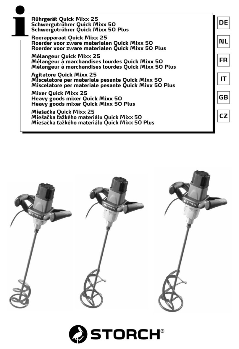
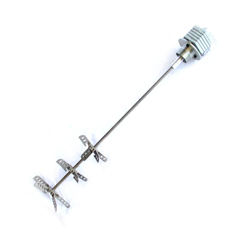
Neumaerker 05-50710 User manual

Lohstr.
13
-
58675
Hemer/
Postfach
4063
-
58663
Hemer
Telefon:
+49
2372
9274-0
Fax:
+49
2372
3304
DEUTSCHLAND
Operating
Manual
Spiral
Mixer
art.-no.
05-50710
www.neumaerker.de

MIXER
CONTENTS
1
GENERAL
INFORMATION
Purpose
of
the
msnual
4
Manufacturer
and
machine
idenlification
4
Machine
descriptions
5
Technical
specifications
5
Overall
dimensions
6
Safely
devices
8
Safely
Information
8
Residual
risks
9
2
INSTALLATION
INFORMATION
Packaging
and
unpacking
10
Installation
area 10
ElectricaJ
connections
10
3
USE
AND
CLEANING
INFORMATION
Control
descriptions
11
Mixer
use
11
Whip
use
,
12
Recommendations
for
use
12
Endof
theday
cleaning
13
Extended
periods
of
disuse 13
4
TROUBLESHOOTING.
RECYCLING
Introduction
14
Problems,
causes,
Solutions
14
Disposal
and
recycling
14
ATTA
CH
WIE
NTS
Spare
parts
catalogue
Wiring
diagram

GENERAL
INFORMATION
1
Purpose
of
the
manual
This
manual
was
written
by
the
Manufacturer
and
is
an
integral
part
of
machine
equipment.
During design
and
construction
the
Manufacturer
has
carefülly
considered
possible
hazards
and
personal
risks
that
may
result
from
interaction
with
the
machine.
In
addition
to
observing
the
specific
laws
in
force.
the
manufacturer
has
adopted
all
"exemplary
construction
technique
principles".
The
purpose
of
this
Information
is
to
advise
the
users
to
adopt
extreme
caution
to
avoid
risks.
However,
discretion
is
invaluable.
Safety
is
also
in
the
hands
of
all
the
Operators
who
interact
with
the
machine.
Keep
this
manual
in
a
suitable
place,
always
within
reach
for
consultation.
The
following
Symbols
are
included
to
better
stress
some
passages:
DANGER
-
WARNING:
indicates
hazards
that
may
cause
serious
damages;
attention
is
required.
INFORMATION:
indicates
particularly
important
technical
Information.
The
following
is
enclosed
with
this
manual:
-
Warranty
certificate
describing
the
Manufacturer's
warranty
conditions.
-
Documents
that
prove
conformity
with
effective
health
and
safety
laws.
Contact
the
Authorised
dealer
for
any
Service
request,
Information
or
spare
parts
order.
Machine
and
manufacturer
identification
Manufacturer
Identification"
Serial
number
-
Conformity
markings
*
-•Ä
Qv.
o
V||H-
'
Kl!
W
Machine
model
Year
of
manufacture
Technical
speclfications

GENERAL
4
INFORMATION
■
Machine
descriptions
The
mixer
ränge
is
made
up
of
the
following
modeis:
Mod.
MX25
was
designed
for
small
processing
needs.
The
Utensil
has
a
classic
vertical
hold
shape.
The
motor
unit
is
constructed
with
a
plastic
structure
while
the
mixing
Utensil
is
made
up
of stainless
steel,
aluminium
alloy
and
plastic
Clements.
The
machine
has
only
one
speed.
Mod.
MX40
was
designed
for
small-medium
work
needs.
The
Utensil
has
a
classic
vertical
hold
shape.
The
motor
unit
is
constructed
with
a
plastic
structure
while
the
mixing
and
whip
Utensils
are
made
up
of
stainless
steel,
aluminium
alloy
and
plastic
elements.
The
machine
has
one
mixer
speed
and
adjustable
whip
speed.
Mod.
FX40
was
designed
for
small-medium
work
needs.
The
Utensil
has
a
gun
handle
shape.
The
motor
unit
is
constructed
with
a
plastic
structure
while
the mixing
and
whip
Utensils
are
made
up
of stainless
steel,
aluminium
alloy
and
plastic
elements.
The
machine
has
one
mixer
speed
and
adjustable
whip
speed.
Mod.
MX42S
was
designed
for
small-medium
work
needs.
The
Utensil
has a
classic
vertical
hold
shape.
The
motor
unit
is
constructed
with
a
plastic
structure
while the
mixing
and
whip
Utensils
are
made
up
of
stainless
steel,
aluminium
alloy
and
plastic
elements.
The
machine has
only
one
speed.
Mod.
FX42S
was
designed
for
small-medium
work
needs.
The
Utensil
has a
gun
handle
shape.
The
motor
unit
is
constructed
with
a
plastic
structure
while the
mixing
and
whip
Utensils
are
made
up
of
stainless
steel,
aluminium
alloy
and
plastic
elements.
The
machine
has
only
one
speed.
Technical
specifications
Descriptions
Power
supply
Power
Maximum
motor
unit
speed
Net
weight
Packaged
weight
Hand-arm
vibrations
Unit
of
measure
V
Hz
Ph
kW
rpm
kg
kg
m/s2
Noise
level
Installation
Protection
level
Electrical
shock
protection
Directive
compliance
MX25
230V
50/60HZ
1Ph
0.25
15000
2,2
3,4
<2,5
MX40
230V
50/60HZ
1Ph
0.4
15000
4,5
6
<2.5
FX40
230V
50/60HZ
1Ph
0,4
15000
4,5
6
<2,5
MX42S
230V
50/60HZ
1Ph
0,4
15000
3,5
5
<2.5
FX42S
230V
50/60HZ
1Ph
0,4
15000
3,5
5
<2,5
Less
than
70
dB
(A)
Hand-held
Utensil
IPX3
Class
II
93/68/EC
-
98/37/EC
-
2003/108/EC
-
2002/72/EC
-
Regulation
(EC)
n°
1935/2004
-
2004/108/EC
-
2006/95/EC

GENERAL
4
INFORMATION
I
MX25
On
button
.
Motor
unlt
)
----
'Lock
nut
.Mixer
'utensll
MX40-MX42S
Speed
~_regulator
(MX40
only)
"""
On
button
Motor
unlt
Lock
nut
Mixer
*
Utensil
FX40-FX42S
Speed
regulator
(FX40
only)
"*""
On
button
.
Motor
unlt
-Lock
nut
Whip
utensll
(FX-MX40
only)
Overall
dimensions
mm
MX25
MX40
FX40
MX42S
FX42S
A
270
400
400
400
400
B
410
500
500
500
500
C
170
170
170
170
170

GENERAL
4
INFORMATION
■
MX25
!U
'-
505
MX40-MX42S
:\
FX40-FX42S
n
■•
■<:.
!
I
•
k:\

GENERAL
4
INFORMATION
I
Safety
devices
Forced
retension
on
button:
Releasing
the
button
cuts
off
power
to
the
Utensil
and
turns
it
off,
stopping
the
Utensil
Switch
protection:
The
protection
protects
the
■"Operator
from
accidentally
starting
the
Utensil
in
normal
work
conditions.
Safety
Information
•
Careful
consultation
of
this
manual
before
installation
and
use
is
essential.
Continual
observance
of
the
indications
found
in
the
manual
guarantee
personal
and
machine
safety.
•
Never
tamper
with
safety
devices
for
any
reason.
•
Strict
observance
of
the
work
safety
regulations
issued
by
the
responsible
organisations
in
each
country
is
strongly
recommended.
•
The
manufacturer
is
not
liable
for
damages
to
persons
or
things
due
to
the neglect
of
safety
regulations.
•
Correct
machine
placement,
illumination
and
cleanliness
are
important
conditions
for
personal
safety.
•
Do
not
expose
the
machine
to
the
elements.
•
Machine
connections
and
start-up
must
only
be
performed
by
specialised
technicians.
•
Make
sure
that
the
system
specifications
of
the
room
where
the
machine
is
installed
correspond
to
the
Information
printed
on
the
plate.
•
Make
sure
the
machine
is
connected
to
a
grounding
system.
•
The
work
area
around
the
machine
must
always
be
kept
clean
and
dry.
•
Use
the
garments
foreseen
by
work
safety
regulations.

GENERAL
A
INFORMATION
•
This
Utensil
must
only
be
used
for
its
specific
purpose:
any
other
use
is
considered
improper
and
therefore
hssardous.
•
Check
the
stiitabitity
and
weight
of
products
to
be
processed;
do
not
overload
the
machine.
•
Introducing
objects,
tools,
hands
or other
things
within
hazardous
parts
is
forbidden
•
Keep
the
machine
away
from
children.
•
Disconnect
the
power
cord
from
the
electrical
socket
when
the
machine
is
not
in
use.
■ In
the
event
of
malfunctions
and/or problems,
do
not
attempt
to
repsir
Ihe
machina.
Contact
the
authorised
dealer.
•
Use
original
spare
parts.
•
Before
cteaning
the
machine,
disconnect
the
power
supply
by
unplugging
the
machine.
•
Do
not
ciean
with
high-pressure
jets
of
water.
Residual
risks
In
accordance
with
point
1.7.2
"Residual
risk
warnings"
in
Machine
Directive
98/37/EC
and
further
amendments.
please
note
that
the
safety
guards,
constructed
in
accordance
with
said
Directive.
do
not
completely
eliminate
cutting
and
irapping
nsks
to
upper
limbs.
Ak.
DANGER
-
WARN1NG:
Nevcr
near
upper
Ümba
or
other
body
parts
to
the
indicated
Utensil
areas
when
insertctl
in
the
moter
imii.
Only
clean
Utensils
removed
fnim
the
niotor
11 ii
it.

INSTALLATION
INFORMATION
2
Packing
and
unpacking
The
machine
is
packaged
in
cardboard
with
polyester
foam
inserts
to
guarantee
füll
integrity
during
transport.
•
Handle
the
packaging
according
to
the
instructions.
•
Open
the
packaging
and
check
the
integrity
of
all
components.
Keep
packaging
for
future
moves.
•
Lift
the
machine
as
indicated
and
place
it
in
the
installation
area.
Installation
area
The
arranged
area
must
be
suitably
illuminated
and
an
electrical
socket
must
be
available.
The
resting
surface
must
be
sufficiently
ample,
even
and
dry.
The
fry
top
must
be
instalied
in
rooms
with
non-explosive
environments.
In
any
case,
installation
must
also
be
performed
in
consideration
of
the
work
safety
laws
in
force.
Room
conditions
table
Descriptions
Working
temperature
Storage
temperature
Relative
humidity
Dustiness
Values
0+35
°C
(32+95
°F)
-15
to
+65
"C
(from
-6.8
to
+149
°F)
Maximum
80%
with
20
°C
room
temperature
Maximum
50%
with
room
temperature
between
20+60
°C
Less
than
0.03
g/m3
Electrical
connections
DANGER
-
WARNING:
Electrical
connections
to
the
supply
mains
must
be
performed
by
specialised
personnel.
Verify
the
efficiency
of
the
grounding
System
in
the
building.
Make
sure
that
line
voltage
(V)
and
frequency
(Hz)
correspond
to
those
of
the
machine
(See
the
identification
plate
and
wiring
diagram).
The
machine
is
equipped
with
an
electrical
cord
that
connects
to
a
multi
polar
plug.
The
plug
is
to
be
connected
to
a
wall
switch
equipped
with
a
circuit
breaker.
i'
■
i
t
\
V:
/
J
Single
phase
230V-
.?.:
\
connection
1Ph
Ph N
o
•
-]
i
j
10

USE
AND
CLEANING
INFORMATION
3
Control
descriptions
1)
On
button
Press
the
button
to
Start
the
machine.
Release
to
stop
the
machine.
2)
Speed
adjustment
knob
(MX40-FX40
only)
The
speed
adjustment
knob
both
adjusts
Utensil
speed
and
directly
by-passes
to
maximum
machine
speed.
To
switch
from
one
condition
to
another,
rotate
the
knob
one
notch.
a)
Adjustable
speed
(only
use
with
the
whip
Utensil):
-
on
FX40,
it
is
marked:
1\
Q
•
on
MX
40
it
is
numbered
from
1
to
10
b)
Maximum
speed
(only
use
with
the
mixer
Utensil):
-
on
both
MX40
-
FX40
modeis,
it
is
marked:
MX25
f/Es.
V
MX40-MX42S
2
Mixer
use
-
Insert
the
mixer
Utensil
in
the
motor
unit
and
tighten
the
Utensil
lock
nut.
-
Connect
the
motor
unit
to
the
power
plug.
-
For
MX40
-
FX40
modeis,
turn
the
speed
adjustment
knob
to:
-
Firmly
hold
the
mixer
lock
nut
with
one
hand
and
the
motor
unit
handle
with
the
other.
-
Insert
the
mixer
in
the
Container
with
the
product
to
be
processed.
-
Press
the
on
button
being
careful
not
to
near
hands
or
any
other
part
of
the
body
to
the
area
where
the
mixer
blades
are
located.
-
When
finished,
release
the
on
button
to
stop
the
Utensil
and
remove
the
Utensil
from
the
Container.
4k
DANGER
-
WARNING:
Never
near
upper
limbs
or
other
parts
of
the
body
to
the
area
where
the
mixer
Utensil
blade
is
located
when
inserted
in
the
motor
unit.
Only
clean
Utensils
removed
from
the
motor
unit.
MX2S-MX40-MX42S
SU!
FX40-FX42S
1
n
•
JFf
11

USEANDCLEANING
INFORMATION
Whip
use
•
Insert
the
whip
Utensil
in
the
motor
unit
and
tighten
the
Utensil
lock
nut.
-
Connect
the
motor
unit to
the
power
plug.
-
For
mod.
MX40,
turn
the
speed
adjustment
knob
to
a
number
between
1
and
10.
-
For
model
FX40,
turn
the
speed
adjustment
knob
to:
Tl
a
-
Firmly
hold
the
mixer
lock
nut
with
one
hand
and
the
motor
unit
handle
with
the
other.
-
Insert
the
whip
in
the
Container
with
the
product
to
be
processed.
-
Press
the
on
button
being
carefui
not
to
near
hands
or
any
other
part
of
the
body
to
the
area
where
the
whips
are
located.
-
Rotate
the
speed
adjustment
knob
to
select
the
best
rotation
speed
for
the
process.
-
When
finished,
release
the
on
button
to
stop
the
Utensil
and
remove
the
whip
Utensil
from
the
Container.
DANGER
-
WARNING:
Ncver
near
upper
limbs
or
other
parts
of
the
body
to
the
area
where
the
mixer
Utensil
is
located
when
inserted
in
the
motor
unit.
Only
clean
Utensils
removed
from
the
motor
unit.
Recommendations
for
use
Use
the
mixer
Utensil
in
Containers,
making
sure
to
rest
the
protective
blade
hood
on
the
bottom
so
that
processing
product
never
exceeds
the
maximum
level
notch
on
the
Utensil
(2/3
of
the
accessory).
I
Use
the
whip
tool
in
Containers,
making
sure
never
to
rest
the
two
whips
on
the
bottom
and
so
that
the
gear
box
is
always
out
of
the
processing
product.
INFORMATION:
Be
very
carefui
never
to
submcrge
the
whip
Utensil
gear
box
in
processing
product
to
avoid
damaging
the
gear
unit
inside.
12

USEANDCLEANING
INFORMATION
End
of
the
day
cleaning
•
Unplug
the
motor
unit
from
the
power
socket.
•
Remove
Utensils
from
the
motor
unit.
Wash
the
mixer
Utensil
under
running
water
(only
when
the
Utensil
is
removed
from
the
motor
unit).
•
Remove
the
whips
from
the
whip
Utensil
and
wash
them
under
running
water
(only
when
the
Utensil
is
removed
from
the
motor
unit).
•
Hang
the
Utensils
with
the
mixer
ends
(mixer
blade
or
whips)
facing
down.
•
Clean
external
motor
unit
parts
with
a
damp
sponge
and
dry
(only
perform
this
Operation
when
unplugged
from
the
power
socket).
•
Do
not
use
metallic
pads
and
abrasive
detergents.
•
Accurately
clean
using
neutral
products.
Extended
periods
of
disuse
For
extended
periods
of
disuse,
unplug
the
Utensil
from
the
power
socket,
clean
the
Utensil
and
cover
it
with
a
cloth
to
protect
if
from
dust.
13

TROUBLE
SHOOTING,
RECYCLING
Introduction
In
the
event
of
breakdown
or
maifunctioning,
turn
off
the
wall
fuse
and
contact
your
Dealer's
Service
centre.
Avoid
dismantling
internal
machine
parts.
The
manufacturer
is
not
liable
for
any
machine
tampering!
Problems,
causes,
Solutions
Problem
The
machine
does
not
Start
Cause
Main
switch
off
No
power
reaches
the
motor
unit.
Solution
Turn
on
main
switch
to
"1"
Contact
your
dealer's
Service
centre
Disposal
and
recycling
The
markings
illustrated
here
(barred
garbage
bin),
on
the
Utensil
data
plate,
indicates
that
at
the
end
of
its
working
life,
the
Utensil
must
be
disposed
of
and
recycled
according
to
European
Directive
2002/96/EC
and
subsequent
amendments.
The
Directive
provides
for
the
separate
collection
of
electric
and
electronic
equipment
by
a
collection
System
called
RAEE.
Upon
purchasing
a
new
Utensil,
the
user
must
not
dispose
of
the
Utensil
as
urban
waste
but
must
return
it,
in
a
one-to-one
exchange,
to
the dealer
or
distributor.
The
dealer
may
dispose
of
the
Utensil
following
the
procedures
set
by
the
RAEE
collection
System.
In
the
event
the
user
disposes
of
the
Utensil
without
purchasing
a
new
one,
in
Italy
contact
the
manufacturer
who
will
provide
suitable
information
on
machine
disposal
at
the
collection
centre
dosest
to
the
user.
Users
who
do
not
reside
in
Italy
must
contact
the
Ministry
of
the
Environment
in
their
countries
who
will
provide
information
necessary
for
correct disposal.
Failure
to
observe
the
disposal
procedure
may
cause
harmful
effects
on
the
environment
and
people.
Therefore,
total
or
partial
illicit
Utensil
disposal
by
users
is
punishable
by
local
authorities.
14

CATÄLOGO
PARTI
DI
RICAMBIO
•
SPARE
PARTS
CATALOGUE
•
CATALOGUE
PIECES
DE
RECHANGE
•
ERSATZTEILKATALOG
•
CATÄLOGO
DE
REPUESTOS
•
CATÄLOGO
DE
PECAS
SOBRESSALENTES
•
KATAJ10r3AnHACTEM
MX40
MX42S
37—
28
29!
19!
36
-31!

CATÄLOGO
PARTI
DI
RICAMBIO
•
SPARE
PARTS
CATALOGUE
•
CATALOGUE
PIECES
DE
RECHANGE
•
ERSATZTEILKATALOG.
CATÄLOGO
DE
REPUESTOS
•
CATÄLOGO
DE
PECAS
SOBRESSALENTES
•
KATAJlOr
3AT1HACTEM
MX40
MX42S
Rif
No
1
2
3
4
5
6
7
8
9
10
11
12
13
14
15
16
17
18
19
20
21
22
23
24
25
25
25
25
26
28
29
30
30
30
30
31
32
"34~
3b
36
36
36
"37~
38
Codice
Code
SL0762
SL3382
SL2997
SL3414
SL0757
SL3080
SL3081
SL3444
SL3443
SL3446
SL3445
SL2899
SA1063
SL3611
SL3612
SL0739
SL0746
SL0740
SL0271
SA1002
SA8900
SA8800
SL0733
SL0743
SL0976
SL0776
SL0978
SL0979
SL0741
SL3391
SL0879
SL0773
SL0972
SL0747
SL0974
SL0975
SL3415
SL1454
SL0772
SL0744
ME4030
ME4040
ME4050
FRUSTAFM3
SL3413
•
•
•
•
•
•
•
•
•
(*):
fuori
produzlone
/
c
Caratterlstlche
Characteristics
Green
230V/1Ph/50-60Hz
(MX40)
(MX42S)
Green
Green
Green
Green
Green
Green
230V/1Ph/50-60Hz
Green
(MX40)
8x18x5
608H
21
inox
Assemblv
(MX40)
(MX40)
(MX40)
(MX40)
(1)4X40)
L=300mm
L=400mm
(Standard)
L=500mm
L=600mm
OR128
L=300mm
L=400mm
(Standard)
L=500mm
L=600mm
8x18x6
vTs
L=300mm
assembly
L=400mm
assemblv
(Standard)
L=500mm
assembly
Assembly
(MX40)
(MX40)
ut
of
production
Descrizione
Oescription
Passacavo
Cable
damp
Piastra
Plale
Scheda
eletlronica
Electronic
card
Inserto
Insert
Pulsante
Push
bullon
Copertura
Covering
Copertura
Coverina
Tappo
Cap
Tappo
Cap
Tappo
Cap
Tappo
Cap
Motore
Motor
Giunto
Joint
Inserto
insert
Flangia
Flanae
Ingranaqqio
Gear
Paraolio
Oil
seal
Boccola
Bush
Cuscinetto
Bearinq
Supporto
Support
Inqranaggio
Gear
Ingranaaaio
Gear
Scatola
Box
Frusta
VVhisk
Albero
Shaft
Albero
Shaft
Albero
Shaft
Albero
Shaft
Supporto
Support
Ghiera
Locking
ring
Boccola
Bush
O-rinq
O-rinq
Tubo
Tube
Tubo
Tube
Tubo Tube
Tubo Tube
Protezione
Protection
Paraolio
Oil
seal
V-ring
V-rinq
Coltello
Cutter
Utensile
mescolatore
Mixer
tool
Utensile
mescolatore
Mixer
tool
Utensile
mescolatore
Mixer
tool
Utensile
frusta
Whisk
tool
Rotella
Wheel
9:
ricamblo
conslgllato
/
spare
part
suggested

«RKIS
OUGRAM
•
SCHEMA
ELECTRIQUE
•
ELEKTRISCHER
ELECTRICO
•
ESQUEMA
ELECTRICO
•
3JIEKTPMMECKAJ1
CXEMA
MX40
FX40
DD
ID
D
o
c
K
i
i—
Push
button
//
/T\
Speed
variator
n
Motor
This manual suits for next models
5
Table of contents
Popular Mixer manuals by other brands

Mondial Designs Limited
Mondial Designs Limited M-11 Instruction and Technical Service Manual

Scarlett
Scarlett SC-HM40S09 instruction manual

Team International
Team International TEAM MS 17 operating instructions
Termozeta
Termozeta Bellacucina Instruction booklet
Samson
Samson MDR 8 Specification sheet

KitchenAid
KitchenAid KP50PS Instructions and recipes
