Neumann RSM 191 User manual

Bedienungsanleitung
Operating Instructions
RSM 191 - System
Ollenhauerstr. 98
13403 Berlin
Germany
Tel.: +49-30 / 417724-0
Fax: +49-30 / 417724-50
Email: [email protected]
Web: www.neumann.com

2
Inhaltsverzeichnis
1. Kurzbeschreibung
1.1 Belegung der Ausgangsbuchsen
2. Das Kondensator-Richtrohr-Stereomikrophon
RSM 191
2.1 Einsatzgebiete
2.2 Aufnahmeebene
2.3 Aufnahmewinkel, Arbeitsbereich
2.4 Monokompatibler Arbeitsbereich
2.5 Tiefenfrequenzgang des Seitensignals
3. Der Matrixverstärker MTX 191 A
3.1 Der Seitenpegelschalter
3.2 Der Matrixschalter
3.3 Der Hochpaßschalter
3.4 Die Stromversorgung
3.5 Der 10 dB-Dämpfungsschalter
4. Mikrophonkabel
5. Stromversorgung
5.1 Batteriespeisung
5.2 Phantomspeisung
5.3 Betrieb mit Netzgeräten
5.4. Betrieb an unsymmetrischen oder mittengeer-
deten Eingängen
6. Einige Hinweise zur Pflege von Mikrophonen
7. Technische Daten
8. Frequenzgänge und Polardiagramme
9. Empfehlungen für den Gebrauch der
Windschutzeinrichtungen
10. Zubehör
11. Schaltbild
Table of Contents
1. Summarized Description
1.1 Output Configuration
2. The RSM 191 Condenser Shotgun Stereo
Microphone
2.1 Applications
2.2 Pick-up Plane
2.3 Pick-up Angle, Working Range
2.4 Mono-compatible Working Range
2.5 Low-frequency Response of Side Signal
3. The MTX 191 A Matrix Amplifier
3.1 Side Level Switch
3.2 Matrix Switch
3.3 High-pass Switch
3.4 Power Supply
3.5 10 dB Attenuating Switch
4. Microphone Cables
5. Power Supply
5.1 Battery Operation
5.2 Phantom Powering
5.3 AC Supply Operation
5.4. Operation with Unbalanced or Center-Tap
Grounded Inputs
6. Some Remarks on Microphone Maintenance
7. Technical Specifications
8. Frequency Responses and Polar Patterns
9. Recommendations for the Use of Wind
Screening Devices
10. Accessories
11. Circuit Diagram

3
1. Kurzbeschreibung
Der RSM 191-System-Koffer enthält:
• das Richtrohr-Stereomikrophon RSM 191
• den Matrixverstärker MTX 191 A
• das 7-polige Verbindungskabel KT 5 (RSM 191 –
MTX 191 A)
• das Adapterkabel AC 20 (MTX 191 A – auf zwei
Mikrophoneingänge)
• den Schaumstoffwindschutz WS 191
Durch Herausnehmen des Schaumstoffeinsatzes für
das RSM 191 ist im Koffer Platz für einen Windkorb
WK 81 mit Handgriff HG 82 und Elastischer Aufhän-
gung EA 30 B mt.
Das Mikrophon RSM 191 liefert ein Mittensignal (M)
mit keulenförmiger Richtcharakteristik und ein Seiten-
signal (S). Das Seitensignal hat eine zur Mikrophon-
achse querliegende Achtercharakteristik. Die Richtungs-
zuordnung links/rechts ist auf dem Mikrophon markiert.
Im Matrixverstärker kann zur Variation der Stereo-Ba-
sisbreite die Verstärkung des Seitensignals relativ zum
Mittensignal von +6 dB bis –9 dB in jeweils 3 dB-Stu-
fen verändert werden.
In Stellung 0 dB haben beide Systeme den gleichen
Übertragungsfaktor von 23 mV/Pa.
Tieffrequente Signale werden mit einem Hochpaßfil-
ter unterdrückt. Die Grenzfrequenz kann von 40 Hz
auf 80 Hz bzw. 200 Hz umgeschaltet werden.
Zum Schutz vor Übersteuerung kann die Empfindlich-
keit beider Systeme um 10 dB vermindert werden.
Das Ausgangssignal des Mikrophons steht an den bei-
den Ausgängen des Matrixverstärkers MTX 191 A je
nach Schalterstellung entweder als MS-Signal oder als
XY-Signal zur Verfügung.
Das Mikrophonsystem kann entweder mit einer 9 V-
Blockbatterie oder extern aus einer 48 V-Phantom-
speisung versorgt werden.
Das RSM 191-System ist kompatibel mit dem
RSM 190 i System. Matrixverstärker und Mikrophone
können beliebig kombiniert werden. Es ist jedoch dar-
auf zu achten, daß das zum jeweiligen Matrixverstär-
ker passende Verbindungskabel benutzt wird
(MTX 190 i: KT 3/KT 4; MTX 191 (A): KT 5/KT 6).
RSMRSM
RSMRSM
RSM 191191
191191
191 A-SA-S
A-SA-S
A-S .................... sw ............................. Best.-Nr. 07087
1. Summarized Description
The RSM 191 System case contains:
• the RSM 191 Shotgun Stereo Microphone
• the MTX 191 A Matrix Amplifier
• the 7-pole KT 5 connecting cable (RSM 191 –
MTX 191 A)
• the AC 20 adapter cable (MTX 191 A – to two
microphone inputs)
• the WS 191 polyurethane windscreen
By removing the foam plastic insert for the RSM 191,
space is made in the case for a WK 81 windscreen
with HG 82 handle and EA 30 B mt elastic suspen-
sion.
The RSM 191 microphone delivers a middle signal (M)
with a lobe shaped characteristic and a side signal (S).
The side signal has a figure-8 characteristic at right
angles to the microphone axis. Engraved letters L and
R permit left/right coordination.
The matrix amplifier permits a variation of the base
width of the stereo sound image through variation of
the side signal level in a range of +6 dB to –9 dB
relative to the middle signal in steps of 3 dB each.
In position 0 dB both systems offer an identical sensi-
tivity of 23 mV/Pa.
Low-frequency signals are suppressed by a high-pass
filter. The cut-off frequency can be switched from
40 Hz to 80 Hz or 200 Hz.
As a safeguard against overload the sensitivity of both
systems can be attenuated by 10 dB.
The output signal of the microphone is available at
the two outputs of the MTX 191 A matrix amplifier
either as M/S signal or as X/Y signal, according to the
switch position.
The microphone system can be powered either with
a 9 V block battery or externally by 48 V phantom
powering.
The RSM 191 system is compatible with the
RSM 190 i system. Matrix amplifiers and microphones
can be combined as required. It should be noted, how-
ever, that the appropriate connecting cable must be
used for the matrix amplifier in each case, i.e.
MTX 190 i: KT 3/KT 4; MTX 191 (A): KT 5/KT 6.
RSMRSM
RSMRSM
RSM 191191
191191
191 A-SA-S
A-SA-S
A-S .................... blk .............................. Cat. No. 07087

4
1.1 Belegung der Ausgangsbuchsen
Matrixverstärker MTX 191 A
MTXMTX
MTXMTX
MTX 191191
191191
191 AA
AA
A ....................... sw ............................. Best.-Nr. 07331
(gehört zum Lieferumfang)
5-poliger Steckeinsatz. Die Zuordnung der Mikrophon-
anschlüsse entspricht DIN EN 60268-12 bzw. IEC
60268-12:
Stift 1: 0 V, Gehäuse
Stift 2(+): Kanal I [Mitte (M) oder Links (X)]
Stift 3(–):
Stift 4(+): Kanal II [Seite (S) oder Rechts (Y)]
Stift 5(–):
ACAC
ACAC
AC 20 (120 (1
20 (120 (1
20 (1 m)m)
m)m)
m) ........................................................... Best.-Nr. 06595
(gehört zum Lieferumfang)
Auflösung des 5-poligen Steckverbinders auf zwei Ka-
belstecker XLR 3 M.
Die Kabelfarbe Gelb bezeichnet Kanal I (Mitten- oder
linkes Signal), die Farbe Rot Kanal II (Seiten- oder rech-
tes Signal).
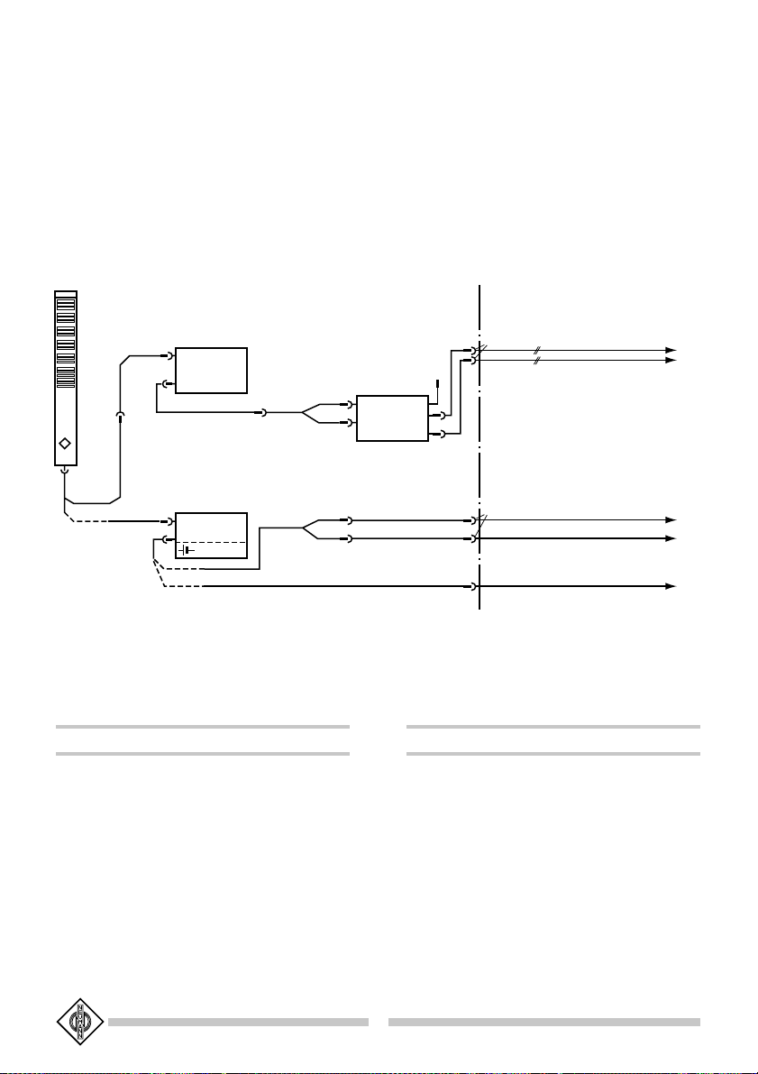
Welches Signal jeweils den Kanälen zugeordnet ist,
kann dem Prinzipschaltbild Abb. 1 entnommen wer-
den.
Die 3-poligen Mikrophonanschlüsse sind entsprechend
DIN EN 60268-12 bzw. IEC 60268-12 beschaltet:
Jeweils
Stift 1 0 V, Gehäuse
Stift 2 (+) Modulation, trafolos symmetrisch
Stift 3 (–) für Phantomspeisung P48 nach
IEC 1938, 3 mA.
(+) Positiver Spannungsanstieg bei einem Schalldruckanstieg vor der Mem-
bran des mittleren Systems (M-Signal) bzw. vor der linken Membran des
Seitensystems (S-Signal).
1.1 Output configuration
MTX 191 A Matrix Amplifier
MTXMTX
MTXMTX
MTX 191191
191191
191 AA
AA
A ....................... blk .............................. Cat. No. 07331
(included in the supply schedule)
5-pin chassis receptacle. Pin assignment according to
DIN EN 60268-12 or IEC EN 60268-12 resp.:
Pin 1: 0 V, Chassis
Pin 2(+): Channel I [Middle (M) or Left (X)]
Pin 3(–):
Pin 4(+): Channel II [Side (S) or Right (Y)]
Pin 5(–):
ACAC
ACAC
AC 20 (1 m)20 (1 m)
20 (1 m)20 (1 m)
20 (1 m) ............................................................ Cat. No. 06595
(included in the supply schedule)
Splits the 5-pin matrix amplifier output into two con-
nectors XLR 3 M.
Yellow cable colour marks channel I (Middle or left-
hand signal), red cable colour marks channel II (side
or right-hand signal).
For signal-to-channel assignment refer to the basic cir-
cuit diagram below (fig. 1).
The pin assignment of the 3-pin connectors is made
acc. to DIN EN 60268-12 or IEC EN 60268-12 re-
spectively:
Both Connectors
Pin 1 0 V, Chassis
Pin 2 (+) Modulation, transformerless and
Pin 3 (–) balanced, for phantom powering
P48 V, 3 mA as per IEC 1938
(+) Positive output voltage as transient response on rising sound pressure in
front of the membrane of the middle system (M-signal) or in front of
the left-hand membrane of the side system (S-signal), respectively.

5
MTX 191 A
RSM 191 KT 5 AC 20
gelb
yellow
rot
red
Kanal
Channel
Kanal
Channel
M
S
-9…0…+ 6 dB
Kanal I
Channel I
Kanal II
Channel II
-S
+S
M-S=Y
M+S=X
M
M
M+S=X
M-S=Y
-MS
MS
XY
-XY
Abb. / Fig. 1

6
2. Das Kondensator-Richtrohr-
Stereomikrophon RSM 191
Das RSM 191 ist ein Studio-Kondensatormikrophon
mit hoher Richtwirkung für die stereophone Aufnah-
metechnik.
Es besteht aus dem Kapselkopf mit zwei getrennten
Kapselsystemen und einem Verstärkerteil, der zwei
voneinander unabhängige transformatorlose Mikrophon-
verstärker enthält.
Das Mittensignal wird durch ein Richtrohrsystem ge-
bildet. Die hohe Richtwirkung verdankt es seiner be-
sonderen akustischen Arbeitsweise:
Die Mikrophonkapsel befindet sich in einem akustisch
offenen, aber mit einem hohen Strömungswiderstand
belegten Gehäuserohr. Daraus resultiert eine hohe
Membranantriebskraft bei kleinem Druckgradientencha-
rakter der Kapsel, und das Mikrophon blendet (Stör-)
Schall außerhalb seiner „Blickrichtung“ wesentlich stär-
ker aus, als es mit Mikrophonen ohne ein solches In-
terferenzrohr möglich ist.
Das Mittensystem vereinigt die hohe Dämpfung für
seitliche Schallanteile (ähnlich der der Hyperniere, ca.
10 dB) mit dem großen Vor-/Rückverhältnis der Super-
niere, indem es von hinten einfallenden Schall ebenfalls
um ca. 10 dB dämpft. Darüber hinaus macht dieses Prin-
zip das Mikrophon unempfindlicher gegen Wind- und
Popstörungen als normale Richtmikrophone.
Das Seitensignal wird durch eine querliegende Acht
gebildet. Zwei entgegengesetzt gerichtete Einzelkap-
seln sind dicht hinter der Richtrohrkapsel angeordnet.
Die Richtungspfeile auf dem Mikrophonrohr dienen als
Orientierungshilfe.
Da zum Erreichen der genannten Mikrophoneigenschaf-
ten keine im Übertragungsbereich liegenden Reso-
nanzwirkungen ausgenutzt werden, ist das Impulsver-
halten des Mikrophons ausgezeichnet, und es vermag,
alle Ausgleichsvorgänge in Musik und Sprache unver-
fälscht zu übertragen.
Der Gesamtinnenaufbau ist zum Schutz gegen Kör-
perschallübertragung und Griffgeräusche vom Außen-
gehäuse entkoppelt.
2.1 Einsatzgebiete
Das RSM 191 System eignet sich besonders für:
• stereophone Reportagen im Freien, auch in stark
geräuscherfüllter Umgebung.
• stereophone Tonaufnahme bei Film und Fernse-
hen, bei der die Schauspieler mittenkonzentriert,
2. The RSM 191 Condenser
Shotgun Stereo Microphone
The RSM 191 is a studio condenser microphone with
a high directivity index for stereophonic sound appli-
cations.
It consists of a capsule head containing two separate
capsule systems and an amplifier section housing two
independent transformerless microphone amplifiers.
The middle signal is formed by an interference tube
system. Its high directional efficiency is the outcome
of its special acoustic mode of operation:
The microphone capsule is located in an acoustically
open but highly flow-resistant housing tube. This re-
sults in a high diaphragm driving force for a low pres-
sure gradient curve of the capsule, and the microphone
fades out (spurious) noise outside its “field of view” to
a much greater extent than a microphone without an
interference tube of this kind is able to do.
The middle system combines the high attenuation of
side sound components (similarily to the hypercardi-
oid, approx. 10 dB) with the high front-to-back ratio
of the super-cardioid by attenuating sound arriving from
the rear likewise by some 10 dB. In addition this prin-
ciple renders the microphone less sensitive to wind
noise and pops compared with other directional mi-
crophones.
The side signal is constituted by a transverse figure-8.
Two opposed single capsules are arranged closely be-
hind the interference tube capsule.
The directional arrows engraved on the microphone
tube serve to aid orientation.
Since no resonance effects anywhere in the frequen-
cy range are exploited to obtain the said microphone
characteristics, the transient response of the micro-
phone is excellent, and it will reproduce all transient
phenomena in music and speech without any discol-
oration.
The entire internal structure is elastically decoupled
from the outer casing to insulate it from structure-
born and handling noises.
2.1 Applications
Some of the important applications of the RSM 191
are:
• Stereophonic electronic news gathering (ENG) out-
doors. It is the ideal microphone for environments
with high ambient noise levels.
• Stereo recordings for TV and motion picture, which

7
Szenengeräusche oder ein Orchester gleichzeitig mit
größerer, einstellbarer Basisbreite aufgenommen
werden.
• stereophonen Filmton, dessen Klangbild in Abhän-
gigkeit von der jeweiligen Einstellung mehr oder
minder breit erscheinen soll. Dies kann sowohl
während der Liveton-Aufnahme als auch bei der
Ton-Nachproduktion geschehen.
Die Vorteile
• Stabile Stereoabbildung und exakte Ortung inner-
halb des gesamten Klanggeschehens.
• Räumliche Perspektive und Verhältnis von Direkt-
schall zu Umgebungsgeräusch über Veränderung der
Basisbreite des stereophonen Klangbildes beeinfluß-
bar.
• Optimale Anpassung an szenische Veränderungen
durch Umschaltung des Aufnahmewinkels.
• „Hineinzoomen“ mitten in die Handlung, dank des
hohen, variablen Bündelungsmaßes.
• Authentische Übertragung des akustischen Schau-
platzes.
• Monokompatible Ausgangssignale in einem 120°-
Aufnahmebereich des Mikrophons.
• Keine Phasenprobleme wegen des minimalen, fes-
ten Kapselabstands.
Die Eigenschaften
• Stereo-Öffnungswinkel elektrisch ferneinstellbar.
• MS- bzw. XY-Stereosignale durch systemeigene
Matrix.
• Durchsichtige und verfärbungsfreie Stereo-Klang-
übertragung durch eng benachbarte, kleine Kapsel-
systeme.
• Hohe Aussteuerbarkeit. Maximale Ausgangsspan-
nung 2,45 Veff (W10 dBu) pro Kanal entsprechend
einem Schalldruckpegel von 134 dB (W100 Pa).
• Hoher Übertragungsfaktor von 23 mV/Pa und da-
durch exzellenter Signal-Geräusch-Abstand.
• Zuschaltbare 10 dB-Dämpfung zur Vermeidung der
Übersteuerung nachfolgender Verstärker bei der
Übertragung sehr hoher Schalldrücke.
• Zuschaltbares Trittschallfilter (Grenzfrequenz 40 Hz,
80 Hz und 200 Hz).
• Kurze Signal-Anstiegszeiten dank der symmetri-
schen, transformatorlosen Technik TLM der Serie
„fet 100®“.
must focus performers much more in the center,
while the orchestra or the overall scenes may have
a wider sonic image.
• For stereophonic motion picture sound, concentrat-
ing or spreading the stereo image according to
changes in the set. It provides the flexibility to do
this either during the live recording or later in post-
production.
Advantages
• It produces highly stable stereo images and focus-
es localization across the whole sound space.
• It provides the operator with control over stereo
width, perspective and the ratio of direct to ambi-
ent sound.
• The side-signal pattern control optimizes the pick-
up for any changes in the recorded event.
• High directional efficiency (hypercardioid) of the mid-
dle-signal system allows it to “zoom” into the ac-
tion.
• It adds true realism with accurately reproduced am-
bience.
• It provides signals with absolutely correct mono
compatibility within a working range of 120°.
• MS uses intensity cues for stereo localization; there-
fore phase differences are virtually non-existent.
Unique features
• Width of stereo image electrically remote control-
lable.
• Built-in matrix provides either MS or XY stereo
signals.
• The recorded sound is without distortion, very
transparent, and virtually without any coloration due
to the small capsules and their close proximity.
• The system has very high overload capability. Max-
imum output level is +10 dB (ref 0.775 V), equiva-
lent to maximum SPL of 134 dB (W100 Pa).
• High sensitivity of 23 mV/Pa for each system pro-
vides excellent S/N ratio.
• Switchable 10 dB attenuation to avoid overloading
follow-on amplifiers when handling very high sound
pressure levels.
• Switchable high-pass filter (cut-off frequency 40 Hz,
80 Hz and 200 Hz).
• TLM transformerless balanced output configuration
of the “fet100®” series assures fast transient re-
sponse characteristic.

8
• Kompakte und extrem leichte Konstruktion. Ge-
wicht des Mikrophons ca. 170 g.
• Wahlweise Phantomspeisung oder Batterieversor-
gung.
2.2 Aufnahmebene
Beim nichtstationären Betrieb des Mikrophons ist zu
beachten, daß das RSM 191 durch die zur Mikrophon-
achse querliegende Achtercharakteristik (Seitensignal)
akustisch nicht rotationssymmetrisch ist. Daher ändert
sich die Aufnahmeebene im Raum, wenn das Mikro-
phon um seine Achse gedreht wird. Dies ist vor al-
lem bei Mikrophonschwenks am Galgen oder an der
Angel zu beachten, weil das Mikrophon meistens ge-
neigt und nicht horizontal montiert ist.
Wird die Links/Rechts-Zuordnung des Mikrophons im
Raum durch Wechseln der Angelposition (z.B. von
oben oder unten) vertauscht, kann dies elektrisch am
Matrixverstärker kompensiert werden. In den Stellun-
gen –MS und –XY wird der Raum entgegengesetzt
der Aufschrift Links/Rechts auf dem Mikrophon abge-
bildet (siehe Kapitel 3.2).
2.3 Aufnahmewinkel, Arbeitsbereich
Der Aufnahmewinkel (= Öffnungswinkel) gibt den Ar-
beitsbereich rechts und links der Mikrophonachse an,
in dem sowohl das Summen- als auch das Differenz-
signal positiv ist (Abb. 2).
• Bei XY-Darstellung ist es der vordere Winkel zwi-
schen den ersten Nullstellen.
• Bei MS-Darstellung wird der Winkel durch die vor-
deren Schnittpunkte zwischen der M- und der S-
Charakteristik gebildet.
• Compact and extremely light-weighted construc-
tion; weight of microphone is approx. 6 oz (170 g).
• Power supply by battery as well as phantom pow-
ering.
2.2 Pick-up Plane
If the RSM 191 is not used in a fixed position, it should
be noted that, because of the figure-8-pattern (side
signal) being transverse to the microphone axis, the
RSM 191 is acoustically not rotationally symmetrical.
For this reason, the pick-up plane is spatially altered
when the microphone is rotated about its axis. This
requires special attention when the microphone is
panned on booms or on a fishpole, as it is then mostly
inclined, and not horizontally mounted.
If the Left/Right-coordination of the microphone with-
in the room is inverted through 180° by changing the
fishpole position from the top or from the bottom,
this can be electrically compensated for at the matrix
amplifier. In the positions –MS and –XY, the spatial
image is formed conversely to the inscription on the
microphone (Left, Right). (See Chapter 3.2).
2.3 Pick-Up Angle, Working Range
The pick-up angle (“field of view”) defines the work-
ing range to the right and left of the microphone axis
in which the sum and difference signals are both pos-
itive (Fig. 2).
• In the XY representation it is the front angle be-
tween the first zero positions.
• In the MS representation the angle is formed by
the two front intersections between the M- and
the S-curves.
20
15
10
5
0
dB
0
45
90
135
18 0
225
270
315°
°
°
°
°
°
°
°
ϕ
20
15
10
5
0
dB
0
45
90
135
18 0
225
270
315°
°
°
°
°
°
°
°
ϕ
Abb. / Fig. 2 Der Öffnungswinkel ϕin der XY- bzw. MS-Darstellung
The pick-up angle ϕin XY- resp. MS-representation

9
2.4 Monokompatibler Arbeitsbereich
In Abb. 3 sind die 3-dB-Grenzen der Mittensignal-Cha-
rakteristik dargestellt, um zu zeigen, daß in einem Be-
reich von etwa 120° (± 60°) ein ungeschwächtes Mo-
nosignal zu erwarten ist. Dieses ist also etwa der
monokompatible Arbeitsbereich. Er ist unabhängigunabhängig
unabhängigunabhängig
unabhängig von
dem eingestellten Seitensignalpegel.
2.4 Monocompatible Working Range
Fig. 3 represents the 3 dB-limits of the middle signal
curve, in order to illustrate that a full mono signal can
be expected over a range of some 120° (± 60°). This
then can be regarded as the mono-compatible work-
ing range. It is independentindependent
independentindependent
independent of the set side signal level.
20
15
10
5
0
dB
0
45
90
135
18 0
225
270
315°
°
°
°
°
°
°
°
2.5 Der Tiefenfrequenzgang des
Seitensignals
Die Seiteninformation wird im RSM 191 von einem
Mikrophonsystem mit Achtercharakteristik aufgenom-
men. Achtermikrophone haben prinzipiell die Tendenz,
für tiefe Frequenzen unempfindlicher als für mittlere
und hohe Frequenzen zu sein. Sie haben also einen
zu tiefen Frequenzen hin abfallenden Frequenzgang.
Dieser physikalische Effekt wird bei diesem Mikro-
phonsystem zur wirkungsvollen Unterdrückung tieffre-
quenter Störsignale wie Körperschall und Windgeräu-
sche ausgenutzt. Damit wird für das Seitensystem –
welches als Mikrophon mit Achtercharakteristik im
Grunde störgeräuschanfälliger ist als das Richtrohrmi-
krophon des Mittensystems – die gleiche hohe Kör-
perschall- und Windgeräuschdämpfung (siehe Fre-
quenzgang, Kapitel 7) wie für das Mittensystem
erreicht.
Wird bei Aufnahmen im Studio (Musik, Hörspiel) kei-
ne erhöhte Anforderung an die Griff- und Windemp-
findlichkeit des Mikrophons gestellt und eine Wieder-
gabe auch tieffrequenter Seitensignalanteile erwünscht,
kann das durch eine elektrische Entzerrung erreicht
werden. Diese wird durch Auftrennen einer Lötbrü-
cke im Mikrophonverstärker aktiviert (siehe auch Fre-
quenzgänge, Kapitel 7). Dazu kann das Mikrophon wie
folgt geöffnet werden:
2.5 Low-frequency Response of the Side
Signal
The side information is picked up in the RSM 191 by
a microphone system with a figure-8 pattern. Figure-8
microphones have an inherent tendency to be less
sensitive to low frequencies than to middle and high
frequencies. They therefore exhibit a frequency re-
sponse which decreases towards the lower frequency
range.
This physical characteristic is utilized in this micro-
phone system to achieve effective suppression of low-
freqency extraneous signals, such as structure-borne
vibrations and wind noise. In this way, the same low
level of structure-borne and wind noise sensitivity is
achieved for the side system (which, as a microphone
with figure-8 polar pattern is fundamentally more sus-
ceptible to extraneous noise than the shotgun micro-
phone used as the middle system) as for the middle
system (see Frequency Responses in Chapter 7).
If, in the case of studio recordings (music, drama) there
is no necessity for the microphone to be particularly
insensitive to structure-borne and wind noise, and the
reproduction of low-frequency side signal components
is more desirable than otherwise, this can be attained
by an electronic equalization circuit, which is activated
by unsoldering a bridge in the microphone amplifier
(see also Frequency Responses, Chapter 7). For this
purpose, the microphone may be opened as follows:
Abb. / Fig. 3

10
Die drei Philips/Kreuzschlitzschrauben am Bodenstück
werden herausgeschraubt. Dann wird der gesamte
Innenaufbau mit Hilfe eines angeschraubten Steckverb-
inders herausgezogen. Die Verstärkerplatine wird sofort
sichtbar und auf ihrer Unterseite kann die oben er-
wähnte Brücke durchtrennt werden (siehe Abb. 4).
Vor dem Zusammenbau muß die Kappe vorne am
Gehäuserohr abgeschraubt werden. Danach kann der
gesamte Innenaufbau wieder in das Gehäuserohr ge-
schoben werden, wobei darauf geachtet werden muß,
daß das Interferenzrohr des Mittensystems nicht am
vorderen Rohrende anstößt, sondern mittig vorsteht.
Erst dann kann die Kappe wieder aufgeschraubt wer-
den. Ein in der Kappe liegender Gummiring zentriert
und hält dabei das Interferenzrohr.
Achtung:
Auf keinen Fall darf mit den Finger auf die Kontaktiso-
lierelemente für die Aufnahme der Kapseln und auf
die hochohmigen Anschlüsse der Hybridbausteine ge-
faßt werden, da geringste Schmutz- oder Fettrückstände
die Isolation herabsetzen und Störspannungen verur-
sachen können.
The three Philips screws at the base are unscrewed;
after which the entire inner construction is lifted out
with the aid of a screwed-on plug connector. The am-
plifier board is immediately visible, and the bridge men-
tioned above can be unsoldered from the underside
(see fig. 4).
Before re-assembly, the cap at the front of the micro-
phone must be unscrewed, after which the entire in-
ner construction can be slipped into the housing tube.
Here, care must be taken to ensure that the interfer-
ence tube of the middle system does not come up
against the front end of the tube, but comes centrally
through it. When this is assured, the cap can be re-
placed, whereby a rubber ring located in the cap centers
and holds the interference tube in position.
Note:
Under no circumstances should fingers come into con-
tact with the contact insulating elements which hold
the capsules, nor with the high-resistance terminals
of the hybrid modules, as the slightest residue of dirt
or grease will reduce the insulation and may give rise
to interference voltages.
Abb. / Fig. 4

11
3. Der Matrixverstärker
MTX 191 A
Der Matrixverstärker MTX 191 A dient zur Verstär-
kung und Matrizierung der MS-Mikrophonsignale (sie-
he Abbildung 1).
Der zur Leistungsanpassung der Mikrophonausgangs-
spannung an die Betriebsspannung üblicherweise ver-
wendete Übertrager ist im MTX 191 A durch eine
elektronische Schaltung ersetzt (TLM-Schaltung), die
– wie ein Übertrager – für eine gute Unterdrückung
von Störsignalen sorgt, die auf die symmetrische Mo-
dulationsleitung einwirken.
3.1 Der Seitenpegelschalter
Der Pegel des Seitensignals kann unabhängig von der
Wahl der Ausgangssignale (MS oder XY) verändert
werden. Dies geschieht mit einem Drehschalter in
3 dB-Schritten von –9 dB bis +6 dB relativ zum Pegel
des Mittensignals.
Bei einer Einstellung des Seitensignals von –9 dB er-
hält man einen Aufnahmewinkel von 170° (±85°) und
eine sehr schwache Räumlichkeitsabbildung.
Durch eine ErhöhungErhöhung
ErhöhungErhöhung
Erhöhung des Seitensignalpegels auf z.B.
+6 dB wird dagegen der Aufnahmewinkel auf 60°
(±30°) eingeengteingeengt
eingeengteingeengt
eingeengt, die Räumlichkeitsabbildung nimmt
dabei stark zu (siehe Abb. 5).
3.2 Der Matrixschalter
Am Ausgang des Matrixverstärkers liegt wahlweise das
MS- oder das XY-Signal, welches durch Summen-
(X = M + S) bzw. Differenzbildung (Y = M – S) aus
dem MS-Signal gewonnen wird. Die Umschaltung er-
folgt mit einem Drehschalter auf der Frontseite des
MTX 191 A.
In Stellung –MS bzw. –XY wird die Links-Rechts-Ab-
bildung vertauscht. Dies geschieht in Stellung –MS
durch Verpolung des S-Signals, in Stellung –XY durch
Vertauschen der beiden Stereokanäle (siehe auch Ka-
pitel 2.2).
3.3 Der Hochpaß-Schalter
Gegen Störgeräusche unterhalb des Übertragungsbe-
reiches ist im Matrixverstärker ein Hochpaßfilter mit
einer Grenzfrequenz von 40 Hz eingebaut (Schalter-
position LIN). Um weiteren Störschall wie starke Wind-
und Trittschallgeräusche auszublenden, kann die Grenz-
frequenz auf 80 Hz bzw. 200 Hz erhöht werden.
3. The MTX 191 A Matrix
Amplifier
The MTX 191 A matrix amplifier is used for amplify-
ing and matrixing the MS microphone signals (see Fig-
ure 1).
The otherwise usual transformer for matching the mi-
crophone output voltage to the operating voltage has
been superseded in the MTX 191 A by an electronic
circuit (TLM circuit), which – in the same way as a
transformer – provides good asymmetry rejection of
spurious signals affecting the symmetrical modulation
line.
3.1 Side Level Switch
The level of the side signal can be varied independ-
ently of the chosen output signal (MS or XY). This is
performed by a rotary switch in steps of 3 dB from
–9 dB to +6 dB relative to the level of the middle
signal.
When the side signal is set to –9 dB, a pick-up angle
of 170° (±85°) is obtained in conjunction with a rela-
tively weak three-dimensional image.
In contrast, when the side signal level is raisedraised
raisedraised
raised
to
+6 dB, for instance, the pick-up angle is constrainedconstrained
constrainedconstrained
constrained
to 60° (±30°), and the three-dimensional image is
markedly raised, too (see figure 5).
3.2 Matrix Switch
At the output of the matrix amplifier there is the op-
tion of the MS- or the XY-signal, which is obtained by
summation (X = M + S) or substraction (Y = M – S)
from the MS-signal of the microphone. Change-over
is by means of a rotary switch on the front of the
MTX 191 A.
In the positions –MS and –XY, the left-right image is
inverted. This occurs in the position –MS by revers-
ing the polarity of the S-signal, and in the position –
XY by reversing the two stereo channels (see also
Chapter 2.2).
3.3 High-pass Switch
The matrix amplifier has a high-pass filter with a cut-
off frequency of 40 Hz to attenuate frequencies be-
low the usable frequency range (switch position LIN).
In order to exclude other extraneous noise, such as
strong wind or structure-borne noise, the cut-off fre-
quency can be raised to 80 Hz or 200 Hz as neces-
sary.

12
20
15
10
5
0
dB
0
45
90
135
18 0
225
270
315°
°
°
°
°
°
°
°
ϕ
20
15
10
5
0
dB
0
45
90
135
18 0
225
270
315°
°
°
°
°
°
°
°
ϕ
S = –9 dB ϕ= 170° S = 0 dB ϕ= 100°
20
15
10
5
0
dB
0
45
90
135
18 0
225
270
315
°
°
°
°
°
°
°
°
ϕ
20
15
10
5
0
dB
0
45
90
135
18 0
225
270
315°
°
°
°
°
°
°
°
ϕ
20
15
10
5
0
dB
0
45
90
135
18 0
225
270
315
°
°
°
°
°
°
°
°
ϕ
20
15
10
5
0
dB
0
45
90
135
18 0
225
270
315
°
°
°
°
°
°
°
°
ϕ
S = –6 dB ϕ= 150° S = +3 dB ϕ= 75°
S = –3 dB ϕ= 125° S = +6 dB ϕ= 60°
Abb. / Fig. 5 Richtcharakteristiken und Öffnungswinkel in Abhängigkeit vom Seitensignalpegel S (XY-Betrieb)
Polar patterns and pick-up angle dependent upon the side signal level S (XY-operation)

13
3.4 Die Stromversorgung
Der Matrixverstärker und das Mikrophon werden ent-
weder durch eine handelsübliche 9 V-Blockbatterie
oder durch eine externe 48 V-Phantomspeisung ver-
sorgt (siehe Kapitel 5).
Der Ein-Ausschalter unterhalb der Leuchtdiode ist nur
bei Batteriebetrieb wirksam.
3.5 Der 10 dB-Dämpfungsschalter
Zur Anpassung an nachfolgende semiprofessionelle
Mikrophoneingänge kann eine 10 dB-Dämpfung einge-
schaltet werden. Die Dämpfung wird durch Reduzie-
rung der Kapselvorspannungen auf ein Drittel ihres
Normalwertes erreicht.
4. Mikrophonkabel
(siehe hierzu auch Abb. 6)
Das Richtrohrstereomikrophon RSM 191 hat einen
7-poligen verschraubbaren DIN-Steckereinsatz. Zum
Anschluß an das Matrixgerät MTX 191 A können fol-
gende Kabel verwendet werden:
KTKT
KTKT
KT 55
55
5(5(5
(5(5
(5 m)m)
m)m)
m) ......................... sw ............................. Best.-Nr. 06719
(gehört zum Lieferumfang)
KTKT
KTKT
KT 66
66
6(10(10
(10(10
(10 m)m)
m)m)
m) ...................... sw ............................. Best.-Nr. 06725
Andere Kabellängen auf Anfrage.
Die Kabel führen auf einen Steckverbinder XLR 7 M
und werden an den Matrixverstärker MTX 191 A an-
geschlossen. Eine Verlängerung ermöglicht das Mikro-
phonkabel (2 x 7-polig XLR):
ICIC
ICIC
IC 7 (107 (10
7 (107 (10
7 (10 m)m)
m)m)
m) ....................... ni ............................... Best.-Nr. 06740
Ausgangsseitig hat der Matrixverstärker einen 5-poli-
gen Steckereinsatz (XLR) und kann über das Mikro-
phonkabel (2 x 5-polig XLR)
ICIC
ICIC
IC 5 (105 (10
5 (105 (10
5 (10 m)m)
m)m)
m) ............................................................. Best.-Nr. 06623
ICIC
ICIC
IC 5 mt (105 mt (10
5 mt (105 mt (10
5 mt (10 m)m)
m)m)
m) ..................................................... Best.-Nr. 06624
verlängert oder auch direkt auf das Adapterkabel
ACAC
ACAC
AC 20 (120 (1
20 (120 (1
20 (1 m)m)
m)m)
m) ........................................................... Best.-Nr. 06595
(gehört zum Lieferumfang)
geschaltet werden, das die beiden Mikrophonkanäle
auf je einen Stecker XLR 3 M führt. Eine weitere Ver-
längerung ermöglichen die 3-poligen XLR-Kabel:
3.4 Power Supply
The matrix amplifier and the microphone can be pow-
ered either by a commercial 9 V block battery or by
an external 48 V phantom powering for each channel
(see Chapter 5).
The on-off-switch below the LED is only active dur-
ing battery operation.
3.5 10-dB Attenuating Switch
The matrix has a 10 dB attenuating switch for match-
ing to follow-on semi-professional microphone inputs.
The attenuation is effected by reducing the capsule
bias voltages to one third of their normal level.
4. Microphone Cables
(see also figure 6)
The shotgun stereo microphone RSM 191 has a 7-pin
DIN connector and is connected to the MTX 191 A
matrix amplifier with either of the following cables:
KTKT
KTKT
KT 5 (5 m)5 (5 m)
5 (5 m)5 (5 m)
5 (5 m) ......................... blk .............................. Cat. No. 06719
(included in the supply schedule)
KTKT
KTKT
KT 6 (10 m)6 (10 m)
6 (10 m)6 (10 m)
6 (10 m) ...................... blk .............................. Cat. No. 06725
Other cable lengths on special order.
The cables end in a connector XLR 7 M and are con-
nected to the matrix amplifier MTX 191 A. An ex-
tension is possible by using the microphone cable (2 x
7-pin XLR):
ICIC
ICIC
IC 7 (10 m)7 (10 m)
7 (10 m)7 (10 m)
7 (10 m) ....................... ni ................................ Cat. No. 06740
At the output side the matrix amplifier has a 5-pin
connector (XLR) and can be extended by using the
microphone cable (2 x 5-pin XLR)
ICIC
ICIC
IC 5 (10 m)5 (10 m)
5 (10 m)5 (10 m)
5 (10 m) .............................................................. Cat. No. 06623
ICIC
ICIC
IC 5 mt (10 m)5 mt (10 m)
5 mt (10 m)5 mt (10 m)
5 mt (10 m) ...................................................... Cat. No. 06624
or can be switched directly to the adapter cable
ACAC
ACAC
AC 20 (1 m)20 (1 m)
20 (1 m)20 (1 m)
20 (1 m) ............................................................ Cat. No. 06595
(included in the supply schedule)
which conveys each of the two microphone outputs
to a plug XLR 3 M. A further extension is possible
by means of the 3-pin XLR cables:
14
ICIC
ICIC
IC 33
33
3mt (10mt (10
mt (10mt (10
mt (10 m)m)
m)m)
m) ............... sw ............................. Best.-Nr. 06543
Für den Einsatz an semiprofessionellen unsymmetri-
schen Eingängen stehen bei Batteriebetrieb Adapter-
kabel zur Verfügung, die den Anschluß des 5-poligen
XLR-Ausgangs des MTX 191 A an folgende Eingänge
ermöglichen:
ACAC
ACAC
AC 22 (0,322 (0,3
22 (0,322 (0,3
22 (0,3 m)m)
m)m)
m) ....................................................... Best.-Nr. 06598
ACAC
ACAC
AC 27 (0,327 (0,3
27 (0,327 (0,3
27 (0,3 m)m)
m)m)
m) ....................................................... Best.-Nr. 06602
ICIC
ICIC
IC 33
33
3mt (10mt (10
mt (10mt (10
mt (10 m)m)
m)m)
m) ............... blk .............................. Cat. No. 06543
For use with semi professional unbalanced inputs,
adapter cables are available for battery operation. These
convey the 5-pin XLR output of the MTX 191 A to
the following inputs:
ACAC
ACAC
AC 22 (0.3 m)22 (0.3 m)
22 (0.3 m)22 (0.3 m)
22 (0.3 m) ........................................................ Cat. No. 06598
ACAC
ACAC
AC 27 (0.3 m)27 (0.3 m)
27 (0.3 m)27 (0.3 m)
27 (0.3 m) ........................................................ Cat. No. 06602
5. Stromversorgung
Das Mikrophonsystem RSM 191 kann mit einer 9 V-
Batterie versorgt oder mit 2 x 48 V phantomgespeist
werden (P48, IEC 1938).
5.1 Batteriespeisung
Der Matrixverstärker MTX 191 A benötigt zur Strom-
versorgung des gesamten Systems nur eine 9 V-Block-
batterie vom Typ IEC 6 F 22. Diese treibt einen
Gleichspannungswandler, der die Batteriespannung auf
48 V transformiert und somit intern eine 48 V-Phan-
tomspeisung zur Verfügung stellt.
5. Power Supply
The RSM 191 microphone system operates on a 9 V
battery or 2 x 48 Volt phantom power (P48, IEC 1938).
5.1 Battery Operation
The MTX 191 A matrix amplifier requires only one
9 V block battery of the type IEC 6 F 22 for the pow-
er supply of the entire system. This battery drives a
dc voltage converter, which transforms the battery pow-
er to 48 V, thus providing a 48 V internal phantom
power supply.
Abb. / Fig. 6 Anschlußmöglichkeiten
Connecting scheme
MTX 191 A
N 48 i-2
MTX 191 A
9 V Batt.
RSM 191
IC 7
KT 5
(KT 6)
KT 5
(KT 6)
IC 5 AC 20
AC 20
AC 22
Netz ~
AC MAINS
I
II
3 F (XLR)
3 F (XLR)
3,5 mm STEREOKLINKENBUCHSE
3.5 mm STEREO JACK
2 x IC 3
MISCHPULT OD. VERSTÄRKERGESTELL
MIXING CONSOLE OR AMPLIFIER RACK
~
~
~
~
I
II
~
~
I,II
~
~

15
The outgoing modulation leads are dc-free.
For connecting to unbalanced inputs, the AC 22 and
AC 27 adapter cables are available, which lead the
5-pin XLR output of the MTX 191 A matrix amplifier
to a 3.5 mm stereo jack plug or to two 6.3 mm mono
jack plugs (see fig. 6).
The battery is inserted in the battery compartment
with the contacts at the front; the positive terminal
must point to the right. The contact carrier in the
battery compartment is appropriately inscribed. Wrong
polarity is mechanically possible, but the micro-
phone will then not function. All zinc-oxide (Darimont),
zinc-manganese, alkaline and also lithium block bat-
teries as per IEC 6 F 22 (dimensions 26.5 x 17.5 x
48.5 mm) are suitable, as are also nickel-cadmium ac-
cumulators of the same size. Mercury batteries of sim-
ilar construction are shorter, and cannot always be re-
lied upon to give proper contact.
Readiness for operation is signified by an LED upon
switching into position “TEST”. The LED does notnot
notnot
not
glow in position “BATT ON”.
Approximately one hour before the battery will no
longer be able to deliver the requisite power, the LED
starts to blink.
An alkaline battery will be exhausted after about
6 hours. Recording pauses afford the battery some
possibility of recovery and extend its overall life.
Note:
If the system is left unused for lengthy periods, it is
recommended to remove the battery from the case,
in order to obviate any possibility of damage due to
leakage.
5.2 Phantom Powering
The “fet100®” series microphones are phantom-pow-
ered at 48 V (P48, IEC 1938).
With phantom powering the dc from the positive sup-
ply terminal is divided via two identical resistors, one
half of the dc flowing through each audio (modula-
tion) conductor to the microphone, and returning to
the voltage source via the cable shield.
Phantom powering provides a fully compatible con-
necting system as there are no voltage differences be-
tween the two audio conductors. Studio outlets so
powered will therefore also accept dynamic micro-
phones or ribbon microphones as well as the modu-
lation conductors of tube-equipped condenser micro-
Die abgehenden Modulationsleitungen sind gleichspan-
nungsfrei.
Für den Anschluß an unsymmetrische Eingänge stehen
die Adapterkabel AC 22 und AC 27 zur Verfügung, die
den 5-poligen XLR-Ausgang des Matrixverstärkers
MTX 191 A auf einen 3,5 mm-Stereoklinkenstecker
bzw. zwei 6,3 mm Monoklinkenstecker führen (siehe
Abb. 6).
Die Batterie wird mit den Kontaktelementen nach vorn
in das Batteriefach eingeführt, wobei der positive An-
schluß nach rechts zeigen muß. Der Kontaktträger im
Batteriefach ist beschriftet. Eine Verpolung ist me-
chanisch möglich, führt aber zu keiner Funktion des
Gerätes. Geeignet sind alle Zink-Kohle, Zink-Mangan,
Alkaline oder auch Lithium-Batterieblöcke nach
IEC 6 F 22 (Maße 26,5 x 17,5 x 48,5 mm) sowie bau-
gleiche Nickel-Cadmium-Akkumulatoren. Bauähnliche
Quecksilber-(Mercury)-Batterien sind kürzer und wer-
den in der Regel nicht oder nicht sicher kontaktiert.
Die Betriebsbereitschaft wird bei Betätigung des Ein-
schalters auf Position „TEST“ durch eine Leuchtdiode
angezeigt. Die LED leuchtet nichtnicht
nichtnicht
nicht in Stellung „BATT
ON“.
Etwa eine Stunde, bevor die Batterie die Stromver-
sorgung nicht mehr sicherstellen kann, beginnt die
Leuchtdiode zu blinken.
Eine Alkaline-Batterie ist nach etwa 6 Stunden unun-
terbrochenem Betrieb erschöpft. Aufnahmepausen ge-
ben der Batterie eine gewisse Erholungsmöglichkeit
und erhöhen die Gesamtbetriebsdauer.
Achtung:
Bei längerem Nichtgebrauch wird empfohlen, die Bat-
terie aus dem Gerät zu nehmen, um eine Beschädi-
gung durch eine eventuell auslaufende Batterie zu ver-
meiden.
5.2 Phantomspeisung
Die Mikrophone der Serie „fet100®“ werden mit 48 V
phantomgespeist (P48, IEC 1938).
Bei Phantomspeisung fließt der Speisestrom vom po-
sitiven Pol der Spannungsquelle über die elektrische
Mitte der beiden Modulationsadern zum Mikrophon.
Er wird hierzu über zwei gleich große Widerstände
beiden Tonadern gleichsinnig zugeführt. Die Rücklei-
tung des Gleichstroms erfolgt über den Kabelschirm.
Mit der Phantomspeisung ist eine kompatible An-
schlußtechnik möglich, weil zwischen beiden Modula-
tionsadern keine Potentialdifferenz besteht. Auf die
Anschlußdosen können daher wahlweise auch dyna-
mische Mikrophone oder Bändchenmikrophone sowie

16
die Modulationskabel röhrenbestückter Kondensator-
mikrophone geschaltet werden, ohne daß die Speise-
gleichspannung abgeschaltet werden muß.
Der Ausgang eines Phantomspeisegerätes darf auch
auf bereits anderweitig P48-gespeiste Mikrophonein-
gänge gesteckt werden.
Trotz der aufwendigen transformatorlosen Schaltungs-
technik des Mikrophonsystems RSM 191 beträgt die
Stromaufnahme des Matrixverstärkers bei der 48 V
Phantomspeisung nur 3 mA je Kanal. Es muß dem-
entsprechend bei der Speisung sichergestellt sein, daß
das verwendete Netzgerät je Kanal einen Strom von
mindestens 3 mA abgeben kann.
Für den Betrieb des Systems müssen immer beide
Kanäle des MTX 191 A gespeist werden.
Wird das Mikrophonsystem phantomgespeist, kann die
Batterie im Batteriefach stecken bleiben. Der Schalter
sollte jedoch nicht in Stellung „ON“ stehen, da sich
die Batterie sonst langsam entlädt.
5.3 Betrieb mit Netzgeräten
Für die Stromversorgung sind alle P48-Netzgeräte ge-
eignet, die mindestens 3 mA je Kanal abgeben.
Das entsprechende Neumann P48-Netzgerät hat die
Bezeichnung N 48 i-2. Es ist zur Stromversorgung zwei-
er Mono-Kondensatormikrophone oder eines Stereo-
mikrophons mit 48 V ± 1 V, maximal 2 x 5 mA, ge-
eignet. Siehe Neumann-Druckschrift Nr. 68832:
„48 V-Phantomspeisegeräte“. Die Zuordnung der Mi-
krophonanschlüsse und die Polarität der Modulations-
adern ist am Ausgang der Speisegeräte die gleiche
wie am Mikrophon.
Das N 48 i-2 wird in folgenden Varianten geliefert:
NN
NN
N4848
4848
48 i-2 (230i-2 (230
i-2 (230i-2 (230
i-2 (230 V)V)
V)V)
V) ............ sw ............................. Best.-Nr. 06500
NN
NN
N4848
4848
48 i-2 (117i-2 (117
i-2 (117i-2 (117
i-2 (117 V)V)
V)V)
V) ............ sw ............................. Best.-Nr. 06502
5.4 Betrieb an unsymmetrischen oder mitten-
geerdeten Eingängen
Das MTX 191 A sowie die 48 V-Phantomspeisegerä-
te BS 48 i, BS 48 i-2 und N 48 i-2 haben gleichspan-
nungsfreie Ausgänge, so daß für den Anschluß an ei-
nen unsymmetrischen Eingang kein Übertrager
erforderlich ist.
Beim RSM 191-System sind Pin 2 und 4 des MTX 191 A-
Ausgangs normgerecht die „heißen Phasen“ und Pin 3
und 5 die „kalten Phasen“. Nach Auftrennen der Mi-
krophonkanäle mit dem Kabel AC 20 (Lieferumfang)
können diese mit entsprechend Abbildung 7 beschal-
phones without the need to switch off the dc power
supply.
No harm is done even if a phantom power supply is
connected to an outlet which is centrally phantom
powered.
Despite the elaborate transformerless circuitry, the
current drain of the RSM 191 microphone system
amounts to a mere 3 mA per channel. It must thus
be ensured that the power unit used for supply can
provide a current of at least 3 mA per channel.
For the operation of the system both channels of the
MTX 191 A must always be powered.
If the microphone system is phantom-powered, the
battery can be left in the compartment. However, the
switch should not be in the “BATT ON” position, as
the battery will then gradually lose its charge.
5.3 AC Supply Operation
All P48 power supplies delivering min. 3 mA per chan-
nel according to IEC 1938 are suitable for powering
the microphone.
The Neumann P48 power supply unit bears the des-
ignation N 48 i-2. It is designed to power either two
monophonic condenser microphones or one stereo
microphone with 48 V ± 1 V, max. 2 x 5 mA. See
also Neumann Bulletin No. 68832 “Phantom 48 Vdc
Power Supplies”. At the output of the power sup-
plies allocation of the microphone connections and po-
larity of the modulation leads is the same as at the
microphone.
The N 48 i-2 is supplied in the following versions:
NN
NN
N4848
4848
48 i-2 (230i-2 (230
i-2 (230i-2 (230
i-2 (230 V)V)
V)V)
V) ............ blk .............................. Cat. No. 06500
NN
NN
N4848
4848
48 i-2 (117i-2 (117
i-2 (117i-2 (117
i-2 (117 V)V)
V)V)
V) ............ blk .............................. Cat. No. 06502
5.4 Operation with Unbalanced or Center-
Tap Grounded Inputs
The MTX 191 A as well as the 48 V phantom pow-
ering units BS 48 i, BS 48 i-2 and N 48 i-2 have dc-
free outputs, so that no transformer is required for
connecting to an unbalanced input.
In the case of the RSM 191-System, pins 2 and 4 of
the MTX 191 A output are the “hot phases”, and
pins 3 and 5 must be connected to ground. After split-
ting the matrix output with the aid of the included
cable AC 20, cables wired as shown in fig. 7 can be

17
utilized for connecting
to unbalanced inputs.
Correct polarity relative
to other studio micro-
phones is thus en-
sured when operating
the RSM 191 system
on unbalanced inputs.
In the case of many
other phantom power-
ing units (except those
mentioned above), not
only the modulation leads to the microphone, but also
the outgoing modulation leads from the powering unit
are at the potential of the feed voltage (+48 V). This
is of no significance for the balanced, floating amplifier
and mixing console inputs in general studio use. On
the other hand, the feed voltage will be short-circuited
when connected to single-sided or center-tap grounded
amplifier inputs, and no operation will be possible.
This can be circumvented as follows:
a) In center tap grounded equipment with input
transformer (e.g. some NAGRA units), the earth lead
can almost always be disconnected without affecting
the function of the equipment.
b) In every outgoing modulation lead, an RC net-
work can be incorporated to block the 48 Vdc voltage
(See Fig. 8 and Neumann-Information no. 84 221).
teten Kabeln an un-
symmetrische Eingänge
angeschlossen werden.
Die richtige Phasenlage
relativ zu anderen Stu-
diomikrophonen ist da-
mit auch bei unsym-
metrischem Betrieb
des RSM 191 gewähr-
leistet.
Bei vielen anderen als
den o.g. Phantomspei-
segeräten liegen nicht nur die Modulationsleitungen
zum Mikrophon auf dem Potential der Speisespannung
von +48 V, sondern auch die vom Speisegerät abge-
henden Modulationsleitungen. Für die in der Studio-
technik allgemein üblichen symmetrischen und erd-
freien Verstärker und Mischpulteingänge ist dies ohne
Bedeutung. Dagegen wird die Speisespannung beim
Anschluß an einseitig oder mittengeerdete Verstär-
kereingänge kurzgeschlossen, und es ist kein Betrieb
möglich.
Es bestehen folgende Lösungsmöglichkeiten:
a) In mittengeerdeten Geräten mit Eingangsübertra-
ger (z.B. einige NAGRA-Geräte) kann die betreffen-
de Erdverbindung fast immer ohne Nachteile für die
Funktion des Gerätes aufgetrennt werden.
b) In jede abgehende Modulationsleitung kann zur
Abblockung der 48 V-Gleichspannung eine RC-Kom-
bination eingefügt werden (siehe Abbildung 8 und
Neumann-Information Nr. 84 221).
Abb. / Fig. 7
Abb. / Fig. 8

18
6. Einige Hinweise zur Pflege von
Mikrophonen
Staubschutz verwenden: Mikrophone, die nicht im Ein-
satz sind, sollte man nicht auf dem Stativ einstauben
lassen. Mit einem Staubschutzbeutel (nicht fusselnd)
wird dies verhindert. Wird ein Mikrophon längere Zeit
nicht verwendet, sollte es in einem Schrank bei nor-
malem Umgebungsklima aufbewahrt werden.
Popschutz verwenden: Ein Popschutz hat nicht nur die
Aufgabe, bei Gesangsaufnahmen die Entstehung von
Poplauten zu verhindern. Er vermeidet auch effizient,
daß sich von der Feuchtigkeit des Atems bis hin zu
Essensresten unerwünschte Partikel auf der Memb-
ran ablagern.
Keine überalterten Windschutze verwenden: Auch
Schaumstoff altert. Das Material kann brüchig und krü-
melig werden. Anstatt das Mikrophon zu schützen,
kann er dann zur Verunreinigung der Mikrophonkap-
sel führen. Überalterte Windschutze also bitte ent-
sorgen.
Funktionstest: Moderne Kondensatormikrophone neh-
men durch lautes Ansprechen keinen Schaden. Zur
Kontrolle, ob ein solches Mikrophon angeschlossen ist,
sollte man es aber keinesfalls anpusten oder an-
poppen, da dies einem akustischen Signal von mehr
als 140 dB (!) entsprechen kann. Normale Sprache ge-
nügt zum Funktionstest völlig.
Selbsthilfe kann teuer sein! Leider kommt es doch
vor, daß durch eine Selbstreparatur mehr beschädigt
als behoben wird. Insbesondere das Reinigen ver-
schmutzter Kapseln erfordert viel Erfahrung und die
Hand eines Fachmanns. Der Lackschutz auf Platinen
zeigt u.a. an, daß dort nicht gelötet werden darf. Eini-
ge Bauteile sind speziell selektiert und können nicht
durch Material von der Stange ersetzt werden. Um
unnötige Kosten zu vermeiden, empfiehlt sich die Ein-
sendung an unsere Vertretungen oder an uns.
Inspektion durchführen lassen: Regelmäßiges Durch-
checken des Mikrophonbestands, wie es einige Schau-
spielhäuser und Rundfunkanstalten praktizieren, kann
bei der Früherkennung von Schäden helfen. Leichte
Verschmutzungen lassen sich eher beseitigen, als eine
untrennbar in die Membran eingebrannte Nikotin-
schicht. Insbesondere bei Mikrophonen im Verleih und
in verunreinigenden Umgebungen empfiehlt sich die
regelmäßige Kontrolle, deren Kosten im Vergleich zu
einer aufwendigen Reparatur sehr gering sind.
6. Some Remarks on Microphone
Maintenance
Use the dust cover: Microphones not in operation
should not be left on the floor stand unprotected. With
a non-fluffy dust cover the microphone can be pro-
tected from dust settling on the capsule. When not
in use for a longer spell, the microphone should be
stored in a closet at standard climatic conditions.
Use a pop screen: The pop screen not only elimi-
nates the plosive pop noises in vocal recordings. In
close-miked vocal applications it also efficiently pro-
tects the diaphragm from almost anything, including
breath humidity down to food particles.
Do not use overaged wind shields: Even the foam
material of wind shields ages. With very old wind
shields, the material decays and becomes brittle. The
particles can then settle on the diaphragm. So, please
dispose of overaged wind shields.
Function testing: Modern condenser microphones can-
not be harmed by very high sound pressure levels.
Still, there is no need for pop-testing to see if a mi-
crophone is working and pulled up on the console.
Normal speech is good enough, and pop-testing can
produce sound pressure levels exceeding 140 dB!
Do-it-yourself can be expensive: Do-it-yourself repairs
can sometimes be more harmful than beneficial. Es-
pecially cleaning soiled capsules does take a skilled
hand and quite some experience. Furthermore, the
protective lacquer shows the parts of the printed cir-
cuit boards where e.g. soldering should be avoided.
Other parts may be specifically selected and cannot
be replaced by standard components. To avoid un-
necessary cost, we recommend sending in defective
microphones to our distributors, or to us directly, for
servicing.
Regular servicing: As some theaters and broadcasters
do on a regular basis, sending in microphones for serv-
icing can help in early recognition of damages. Slight
soiling can be removed much easier than some nico-
tine layer firmly embedded in the diaphragm. Espe-
cially with microphones on loan and in dustier/smoki-
er environments regular checking proves beneficial, as
the cost is rather small compared to a major over-
haul.

19
7. Technische Daten
Akustische Arbeitsweise:
M ......................... Druckgradienten/Interferenzempfänger
S ..................................................... Druckgradientenempfänger
Richtcharakteristik M ......................................................... Keule
Richtcharakteristik S............................................................. Acht
Übertragungsbereich .................................... 20 Hz...20 kHz
Feldübertragungsfaktor1)
bei 1 kHz....................................................... 23 mV/Pa ± 1 dB
Seitensignal
verstellbar um ................................ – 9/– 6/– 3/0/+3/+6 dB
Aufnahmewinkel damit
verstellbar auf................ 170/150/125/100/75/60 Grad
Nennimpedanz ............................................................... 50 Ohm
Nennabschlußimpedanz ..................................... 1000 Ohm
Ersatzgeräuschpegel
CCIR 468-3, M/S ........................................................ 25/31 dB
Ersatzgeräuschpegel
DIN/IEC 651, M/S ...................................................... 16/22 dB
Geräuschpegelabstand
CCIR 468-3, M/S ........................................................ 69/63 dB
Geräuschpegelabstand
DIN/IEC 651, M/S ...................................................... 78/72 dB
Grenzschalldruckpegel für
0,5% Klirrfaktor2) ............................................................... 134 dB
mit Vordämpfung .............................................................. 144 dB
Max. Ausgangsspannung.............................................. 10 dBu
Speisespannung3) ..................................................... 2 x 48 V ± 4 V
Stromaufnahme3) ....................................................................... 2 x 3 mA
Batteriespeisung (altern.) ................... 1 x 9 V ( 6 F 22 )
Erforderlicher Steckverbinder ...................... 2 x XLR 3 F
Gewicht
RSM 191 ................................................................................... 170 g
MTX 191 A ohne Batterie ....................................ca. 390 g
Abmessungen:
RSM 191 ...............................................Ø 30 mm x 212 mm
MTX 191 A (BxHxT) ........................ 80 x 37 x 145 mm
Tragekoffer (BxHxT)..................... 480 x 380 x 140 mm
1 Pa = 10 µbar
0 dB 20 µPa
1) bei 1 kHz an 1 kOhm Nennabschlußimpedanz. 1 Pa 94 dB SPL.
2) Klirrfaktor des Mikrophonverstärkers bei einer Eingangsspannung, die der
von der Kapsel beim entsprechenden Schalldruck abgegebenen Spannung
entspricht.
3) Phantomspeisung (P48, IEC 1938).
7. Technical Specifications
Acoustical operating principle:
M .................. Pressure gradient/interference transducer
S ................................................. Pressure gradient transducer
Polar pattern M .................................................... Lobe-shaped
Polar pattern S ................................................................. Figure-8
Frequency range .............................................. 20 Hz...20 kHz
Sensitivity at 1 kHz1) .................................... 23 mV/Pa ± 1 dB
Side-signal
adjustable by ................................... – 9/– 6/– 3/0/+3/+6 dB
Pick-up angle
thereby ....................... 170/150/125/100/75/60 degrees
Source impedance ....................................................... 50 ohms
Rated load impedance ........................................ 1000 ohms
Equivalent SPL
CCIR 468-3, M/S ........................................................ 25/31 dB
Equivalent SPL
DIN/IEC 651, M/S ...................................................... 16/22 dB
S/N ratio
CCIR 468-3, M/S ........................................................ 69/63 dB
S/N ratio
DIN/IEC 651, M/S ...................................................... 78/72 dB
Max. SPL
for 0.5% THD2) ..................................................................................... 134 dB
with preattenuation ........................................................ 144 dB
Max. output voltage........................................................ 10 dBu
Supply Voltage3) ........................................................ 2 x 48 V ± 4 V
Current consumption3) ..................................................... 2 x 3 mA
Battery supply (altern.) ......................... 1 x 9 V ( 6 F 22 )
Matching connectors ......................................... 2 x XLR 3 F
Weight
RSM 191 ................................................................................... 170 g
MTX 191 A without battery .................... approx. 390 g
Dimensions:
RSM 191 .......................................................... Ø 30 x 212 mm
MTX 191 A (WxHxD) .................... 80 x 37 x 145 mm
Carring case (WxHxD) .............. 480 x 380 x 140 mm
1 Pa = 10 µbar
0 dB 20 µPa
1) at 1 kHz into 1 kOhm rated load impedance. 1 Pa 94 dB SPL.
2) THD of microphone amplifier at an input voltage equivalent to the capsule
output at the specified SPL.
3) Phantom powering (P48, IEC 1938).

20
20 50
100 Hz
200 500 1k 2k 5k 10k 20k
+10
0
-10
-20
dB
8. Frequenzgänge und Polardiagramme
Frequency Responses and Polar Patterns
20 50
100 Hz
200 500 1k 2k 5k 10k 20k
+10
0
-10
-20
dB
M-System
S-System
*Brücke im Mikrophon aufgetrennt (s. Kap. 2.5)
Bridge unsoldered in microphone (see chapter 2.5)
gemessen im freien Schallfeld nach IEC 60268-4
measured in free-field conditions (IEC 60268-4)
gemessen im freien Schallfeld nach IEC 60268-4
measured in free-field conditions (IEC 60268-4)
Other manuals for RSM 191
1
Table of contents
Other Neumann Microphone System manuals


