Neurosoft Neuron-Spectrum-1/V User manual

Technical Manual
Neuron-Spectrum-1/V
Veterinary Digital EEG System
TM012.04.001.000
(08.07.2019)

Neurosoft © 2020
5, Voronin str., Ivanovo, 153032, Russia
P.O. Box 10, Ivanovo, 153000, Russia
Phone: +7 (4932) 24-04-34; +7 (4932) 95-99-99 Fax: +7 (4932) 24-04-35
E-mail: info@neurosoft.com Internet: www.neurosoft.com

3
Contents
Introduction............................................................................................................... 4
Important Safety Instructions .................................................................................. 5
Intended Use....................................................................................................... 5
General Description............................................................................................. 5
Contraindications................................................................................................. 5
Possible Side Effects........................................................................................... 6
Safety Measures.................................................................................................. 6
1. Description......................................................................................................... 7
1.1. Main Specifications....................................................................................... 7
1.2. Principle of Operation ................................................................................... 9
1.3. Connectors and Indicators.......................................................................... 10
1.4. Labeling...................................................................................................... 11
2. Assembly and Installation............................................................................... 13
2.1. Requirements to Personnel ........................................................................ 13
2.2. Room Selection and Placement.................................................................. 13
2.3. Unpacking and Check of Delivery Set......................................................... 14
2.4. System Assembly and Connection.............................................................. 14
3. Proper use........................................................................................................ 16
3.1. Getting Ready............................................................................................. 16
3.2. Getting Started ........................................................................................... 16
3.3. Troubleshooting.......................................................................................... 17
3.4. Actions in Emergency................................................................................. 18
4. Maintenance..................................................................................................... 19
4.1. General Requirements................................................................................ 19
4.2. User Maintenance....................................................................................... 19
4.3. Disinfection................................................................................................. 19
5. Current Repair ................................................................................................. 20
5.1. General Requirements................................................................................ 20
5.2. EEG Cables and Adapters.......................................................................... 20
5.3. Computer Interface Cable (USB Cable)...................................................... 20
5.4. Photic Stimulator......................................................................................... 21
6. Disposal ........................................................................................................... 21
7. Delivery Set and Package Data....................................................................... 21
8. Warranty........................................................................................................... 22
9. Reclamation..................................................................................................... 23
Annex 1. Delivery Set ............................................................................................. 24
Annex 2. Electromagnetic Emissions and Immunity............................................ 25

Neuron-Spectrum-1/V (Technical Manual)
4
Introduction
This technical manual (hereinafter referred to as “the manual”) is the combined docu-
ment describing the operation and servicing of the Neuron-Spectrum-1/V veterinary
digital EEG system (hereinafter referred to as “the system”).
The document certifies technical parameters of the system, which are guaranteed by
the manufacturer.
Do not start working with the system before you have
read this document!
You can send your responses and recommendations to the following address:
P.O. Box 10, Ivanovo, 153000, Russia
or by e-mail:
help@neurosoft.com
You can find additional information about Neurosoft products on our website:
www.neurosoft.com
or ask questions by phone:
+7 (4932) 59-21-12; +7 (4932) 24-04-37 (Service Center)
+7 (4932) 24-04-34; +7 (4932) 95-99-99
You can also contact the Authorized European Representative of Neurosoft,
SAS Neuromed Company (Mr. Benjamin Scholl):
360 avenue du Clapier
ZAС du Couquiou
84320 Entraigues sur-la-Sorgue
France
Phone: +33 621-304-580
E-mail: in[email protected]m
In the USA, please, contact
Diagnus LLC
5 Larson Avenue, Smithtown, NY 11787 USA
+1-(800)-528-0940
https://www.diagnus.us
E-mail: in[email protected]

Important Safety Instructions
5
Important Safety Instructions
Intended Use
The Neuron-Spectrum-1/V veterinary digital EEG system is intended to perform clini-
cal electroencephalography (EEG) and long-latency evoked potential (EP) testing in
animals in any unshielded room.
General Description
The system is intended for veterinary use only!
The Neuron-Spectrum-1/V system is portable and records up to 8 EEG channels and
1 polygraphic channel (for ECG, EOG, etc.). The system can be used in veterinary for:
assessment of brain functions;
detection of epileptic paroxysmal abnormalities;
localization of areas of pathologic activity in brain;
long-term cerebral function monitoring in animals in veterinary hospitals.
Features:
8-channel EEG/EP recording in any unshielded room;
photic stimulation;
long-latency EP recording by EEG channels: flash visual evoked potentials;
amplitude, spectral, periodometric, correlative and coherent EEG analysis, detec-
tion of seizures (spikes and sharp waves), generation of examination report, ex-
port and import of files in the standard EDF data format;
review, storage and printing of recorded traces, results of analysis and exam re-
ports.
Contraindications
Relative contraindications for system application are:
signs of skin inflammation in the places where electrodes are applied;
allergic reactions to the components used for skin preparation and application of
electrodes (conductive gels and pastes, abrasive paste, medical patches);
allergic reactions to silver compounds;
contraindications for sedation (if sedation is used).

Neuron-Spectrum-1/V (Technical Manual)
6
Possible Side Effects
The following side effects can occur rarely:
skin irritation and allergic reactions to the components used for skin preparation
and application of electrodes, allergic reactions to silver compounds.
Safety Measures
Do not use the system unless you read this manual and accompanying documents.
The system is to be used by trained personnel only. No person should attempt to use
this system without necessary knowledge and training to understand its use and how
the results should be interpreted. Before you start using the system read carefully this
manual, the user manual for the Neuron.Spectrum.NET software and the technical
manuals for devices included into the system delivery set.
To ensure safety and exclude the possibility of electric trauma of medical staff
or examined animal, it is PROHIBITED:
to use the system which mounting and setting was done incorrectly without follow-
ing the manual instructions;
to connect the system and surgical HF equipment to the examined animal (it can
lead to the damage of the system or cause flash-burns in the places of electrode
placement);
to connect any devices, not included in the system delivery set, to the electrode
jacks;
to eliminate faults by opening of the system components included in the delivery
set;
to perform tests when the electronic unit, computer or other devices of the system
are opened;
to connect electrodes placed on the examined animal to protective ground or oth-
er conducting surfaces.
to clean the system by submersing into liquid, autoclaving, or steam cleaning as
this may damage equipment or reduce its usable life. The disinfection of the sys-
tem is described in section 4.3 “Disinfection”;
to drop or damage the system. If the system has been dropped or damaged, the
use of the device is permitted only after it is checked and repaired in the author-
ized service center;
to operate the system by children.

Description
7
1. Description
1.1. Main Specifications
Table 1. Main Specifications
Parameters
Values
EEG/EP Channels
Number of channels
8
Sampling rate
100, 200, 500, 1000, 5000 Hz
A/D converter
16 bit
Voltage range
2–12000 µV
Ratio error of voltage measurement:
in the range from 10 to 50 µV
in the range from 51 to 450 µV
±25%
±7%
Sensitivity
1, 2, 5, 7, 10, 20, 50, 70, 100, 200,
500, 1000 µV/mm
Relative error of sensitivity
±5%
Sweep speed at EEG recording
3, 7, 15, 25, 30, 50, 60, 120, 240,
480, 960 mm/s
Sweep speed at EP recording
5, 10, 20, 50, 100, 200, 500 ms/div
Relative error of sweep speed
±2%
High pass filter
0.01, 0.05, 0.5, 0.7, 1.5, 2, 10 Hz
Low pass filter
15, 35, 75, 100, 150, 200, 250 Hz
Common-mode rejection
not less than 100 dB
Suppression ratio of power frequency by notch filter
not less than 40 dB
Input noise level (from peak to peak)
not more than 2 µV
Input impedance
mot less than 100 MΩ
Patient leakage current
not more than 50 nA
Photic Stimulator
Number of channels
1
Stimulus duration
1–60 ms
Relative error of stimulus duration
±10%
Stimulation frequency
1–50 Hz
Relative error of stimulation frequency
±10%
Maximal brightness of LED stimulator
(16000±1600) cd/m2
Left/right/two-sided stimulation
available
General Parameters and Specifications
Interface
USB

Neuron-Spectrum-1/V (Technical Manual)
8
Table 1. Continued
Parameters
Values
Supply voltage:
electronic units
desktop PC-based computer
notebook PC-based computer
5 V DC
220/230 V AC (50 Hz)
110 V AC (60 Hz)
220/230 V AC (50 Hz)
110 V AC (60 Hz)/int. battery
Electronic unit power consumption
not more than 0.25 VA
Dimensions of electronic unit
9513025 mm
Weight of electronic unit
0.5 kg
Weight in package (without PC and printer)
not more than 4 kg
Safety
CF type
Transportation Conditions
Temperature
from -25 to +60°C
Humidity
20 –95%
(non-condensing)
Atmospheric pressure
from 70 kPa
Storage Conditions
Temperature
from +5 to +40°C
Humidity
30-85%
(non-condensing)
Atmospheric pressure
70-106 kPa
Operation Conditions
Temperature
from +10 to +35°C
Humidity
30-85%
(non-condensing)
Atmospheric pressure
70-106 kPa
Safety and Electromagnetic Compatibility
Electromagnetic compatibility (EMC) is provided by conformance to IEC 60601-1-2-
2014 (EN 60601-1-2:2015) requirements.
The system is intended for operation in electromagnetic environment, which special
features are specified in Annex 2.
Portable and mobile RF communication equipment can affect the system operation.
The use of equipment not listed in Table 3 of this technical manual may result in in-
creased emission and system decreased immunity.
As for safety, the system satisfies IEC 60601-1:2012 (AAMI/ANSI ES 60601-
1:2005/(R2012) and A1:2012 and A2:2010/(R)2012, EN 60601-1:2006/A1:2013) and
IEC 60601-1-2-2014 (EN 60601-1-2:2015) and IEC 60601-2-26:2012 (EN 60601-2-
26:2016).

Description
9
The electronic unit is supplied by regulated power supply through USB interface, it
has double isolation and СF type applied parts according to IEC 60601-1:2012
(AAMI/ANSI ES 60601-1:2005/(R2012) and A1:2012 and A2:2010/(R)2012, EN
60601-1:2006/A1:2013).
1.2. Principle of Operation
The principle of operation is based on the acquisition and input of brain biopotentials
and other physiological signals into PC for the analysis of brain electrical activity tak-
ing into account the impact of the other physiological signals.
The system includes the electronic unit that records EEG signals and other physiolog-
ical signals by polygraphic channel, amplify them, convert into digital code and trans-
mitting them to the PC.
The block diagram of the system is shown in Fig. 1.
Fig. 1. The Neuron-Spectrum-1/V system.
Biopotentials from the electrodes are amplified and digitized by means of the analog-
digital converter (ADC) and multiplexer (MPX) under the control of the processor PU1;
then they are transmitted to the USB processor through the optrons of galvanic isola-
tion.
The processor PU1 of the amplifier module controls the modes of measurement, cali-
bration, impedance and internal diagnostics.
The power supply of the amplifier module is performed through the electrically isolated
DC converter (SU1).
The processor PU2 controls the stimulus duration of photic stimulator and it also con-
trols LEDs to indicate impedance.
Neuron-Spectrum-1/V (Technical Manual)
10
All the processors receive commands and transmit data through the USB processor
which forms the data packets to transmit them to the PC and deciphers data transmit-
ted from the PC to control the modules.
The system operates under the control of PC (IBM PC type) with the mouse, key-
board, laser or jet printer and installed licensed Windows 8.1 (or later versions) opera-
tional system.
Signal processing, displaying and presentation in different modes after mathematical
analysis, then storing of the initial data on the hard disk, exam report generation and
printing is done using PC.
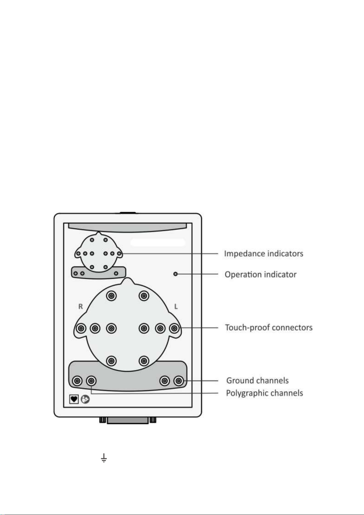
1.3. Connectors and Indicators
The front and side panels of the Neuron-Spectrum-1/V system are shown in Fig. 2
and Fig. 3.
The touch-proof connectors for electrode cables attachment, LED operation indicator
and impedance indicators are located on the front panel (Fig. 2).
Fig. 2. Front panel of Neuron-Spectrum-1/V.
EEG channels are marked as “FP1…O2”, “A1”, “A2”, polygraphic channel is marked
as “1”. The slot is used to attach the ground electrode.

Description
11
The operation indicator glows yellow when the electronic unit is connected to PC and
it glows green when the signal is recorded during the program operation.
The color of impedance indicators means the quality of the electrode placement. The
green color means the quality is high, yellow color –the quality is medium and red
color –the quality is poor. The colors are specified in the software settings.
On the top side panel of the electronic unit (Fig. 3) there are the connector for photic
stimulator, trigger socket (trig-in/trig-out) to attach stimulators of third-party manufac-
turers and connector to attach the system to the PC via USB cable. Other connectors
are designed for other stimulators (not for veterinary use).
Fig. 3. Top side panel of Neuron-Spectrum-1/V.
1.4. Labeling
The example of labeling of the electronic unit is shown in Fig. 4.
Fig. 4. Labeling of electronic unit.
Interpretation of symbols on electronic units:
–mark of conformance to 2012/19/EC “On waste electrical and
electronic equipment (WEEE)” directive.
–mark of conformance to 2014/30/EU of the European Parliament
and of the Council of 26 February 2014 on the harmonization of the
laws of the Member States relating to electromagnetic compatibility.

Neuron-Spectrum-1/V (Technical Manual)
12
ingress protection according to IEC 60529 (EN 60529).
–number according to catalogue by ISO 15223-1.
–serial number by ISO 15223-1.
–date of manufacture by ISO 15223-1.
–manufacturer’s name and address by ISO 15223-1.
–applied parts of СF type according to IEC 60601-1:2012 (AAMI/ANSI
ES 60601-1:2005/(R2012) and A1:2012 and A2:2010/(R)2012, EN
60601-1:2006/A1:2013). This symbol is on the front panel of the
electronic unit.
–attention: consult operational documentation. This symbol is on the
front panel of the electronic unit.
The equipment is identified with the GS1-128 barcode integrated to the barcode in
DataMatrix format (Fig. 5).
Fig. 5. DataMatrix barcode.
Data Matrix is a two-dimensional matrix barcode, consisting of black and white “cells”
or modules of different brightness arranged in either a square or rectangular pattern.
The DataMatrix barcode is described in ISO/IEC 16022:2006 standard.
To decode the data on device, DataMatrix barcode can be read quickly by a barcode
reader or by the smartphone camera as a two-dimensional image.

Assembly and Installation
13
2. Assembly and Installation
2.1. Requirements to Personnel
The assembly and installation of the system should be carried out by a person who is
empowered by the manufacturer or technical personnel of the medical institution
which is going to use it. Remember, that the accuracy of system mounting defines the
safety and quality of its operation. Further mounting and setting requirements which
define the product safety will be marked by bold font in the text.
2.2. Room Selection and Placement
Before installation of the system, select the place for it taking into consideration the
power wiring and protective ground in the room. Please, read the following require-
ments and recommendations:
Requirements concerning the room selection and equipment placement:
The recommended distance from the electronic unit to the nearest electric mains is not
less than 3 meters.
The location of electronic unit in the immediate vicinity (less than 5 meters) with short-
wave or microwave therapeutic equipment is not permitted (it can lead to its unstable
operation).
It is recommended to place the electronic unit on the maximum possible distance from
power cables, switchboards, and different powerful electrical devices which can emit
electromagnetic fields of mains frequency.
The animal environment (within 1.5 meters) should contain only the electronic
units being the medical device with the required safety level. As the computer
equipment safety level is not sufficient for use in the animal environment, it is
necessary to exclude the possibility of animal touching the metal parts of the
computer equipment cases and the simultaneous contact of these parts and an-
imal's body by the personnel. The computer equipment used in the system
should correspond to IEC 60601-1:2012 (AAMI/ANSI ES 60601-1:2005/(R2012)
and A1:2012 and A2:2010/(R)2012, EN 60601-1:2006/A1:2013 or be connected via
the isolation transformer (specialized power supply unit - for notebook PC) cor-
responding to abovementioned requirements.
Requirements to mains:
Do not use electric mains where the neutral conductor and protective ground are com-
bined. It is strongly prohibited.
To prevent an electric shock, the system should only be connected to the mains power
supply with protection grounding.

Neuron-Spectrum-1/V (Technical Manual)
14
The use of multi-socket electric mains extender without additional protective actions is
prohibited. The fact is that the probable break of the circuit of the protective ground of
the multi-socket electric mains extender can lead to summation of leakage current in
all connected units on their metal parts to dangerous values.
Before the system setting, the electrician must check the quality of standard tripolar
sockets and the integrity of the protective ground circuit.
In case the system components are connected to several tripolar sockets, make sure
they are grounded to one and the same protective ground circuit. Otherwise, there is a
danger of several tens of amperes compensating current leakage through the system
connecting cables that leads to the equipment break-down.
2.3. Unpacking and Check of Delivery Set
In case the box with the system was under conditions of the excessive moisture or low
temperature which differs vastly from the working conditions, place the system in the
room with normal conditions and leave it there for 24 hours.
Unpack the box and take the system components out. The delivery set should corre-
spond to the packing report.
The computer equipment packed in the separate boxes should be opened according
to user and technical manuals for these products.
Check the system components and make sure that there is no external damage.
2.4. System Assembly and Connection
Place the computer and electronic unit of the Neuron-Spectrum-1/V system according
to your plan and connect the computer equipment according to the operational docu-
mentation for them.
The software installation and working with the Neuron-Spectrum.NET program is de-
scribed in the user manual.
The software must be installed before the first connection of the system to
PC. Read the corresponding section of the user manual before starting to
work.
If you buy the system with the computer, the equipment is delivered with installed and
configured software. If you purchase the system separately, please install the soft-
ware from the electronic media included in the delivery set.
If the distributive is missing or the software update is required, address to
your local dealer. The authorized Neurosoft dealers are listed on the web-
site: https://neurosoft.com/en/pages/dealers.

Assembly and Installation
15
The connection of the Neuron-Spectrum-1V system to PC is shown in Fig. 6.
Fig. 6. Connection to PC.
Insert the USB cable connector into the USB socket of the computer system unit. The
system must be connected to the USB port on the system unit or to USB hub powered
from the mains. If the system is connected to the USB connectors on a computer
monitor or keyboard, it may not work correctly. It is strongly prohibited to use passive
USB hubs (not connected to the mains) as a part of the system.
Place and secure the assembled holder for the electronic unit on the table in the im-
mediate vicinity of the veterinary exam table. Secure the holder mount on the assem-
bled holder. Position the electronic unit on the holder mount.
Assemble the photic stimulator and secure it so that the LEDs can be placed in close
proximity (10-30 cm) from the eyes of the examined animal. Connect the cable of the
photic stimulator to the connector for photic stimulator on the top side panel of the
electronic unit.
Connect the needle electrodes to the front panel of the electronic unit.

Neuron-Spectrum-1/V (Technical Manual)
16
3. Proper use
3.1. Getting Ready
Operating Limitations:
Ambient temperature is from +10 to +35С.
Relative humidity is from 30 to 85% (non-condensing).
Atmospheric pressure is from 70 to 106 kPa.
Before the power supply is switched on, make sure that the electronic unit and com-
puter equipment cases have no apparent mechanical failures which can represent
danger.
Power Supply Switch on and System Test
The power supply of the system is switched on by pressing the Power button on the
PC. The electronic unit has no power supply and it is connected to the PC all the time.
The power supply is switched on when the operating system is loaded
and the Neuron-Spectrum.NET program is started.
3.2. Getting Started
Before starting configure the system taking into consideration the exam type and rec-
ommendations of the user manual for this software.
The examination includes the following stages:
preparation of animal for EEG recording and placement of electrodes;
recording of ECG signals;
analysis of the obtained results and their printing.
The electrodes can be applied and connected when the system is switched on. The
needle electrodes are placed subcutaneously according to the fixed veterinary prac-
tice. The example of EEG recording is shown in Fig. 7. The skin is pre-treated with al-
cohol at the sites of electrode placement.

Proper use
17
Fig. 7. EEG recording.
After recording, the electrodes must be removed from the animal and discarded.
If the next exam is not planned till the end of the working day, the system should be
switched off. For that exit the system software and then switch off the computer and
printer. If the long-term dwell in operation is planned (several days or more), power
supply plug of the isolation transformer is recommended to be disconnected to the
power circuit.
3.3. Troubleshooting
The list of some possible troubles and the ways of their removal is given in Table 2.
Table 2. Troubleshooting
Trouble
Cause
Way of Removal
When PC is switched on, the
indicators on its front panel do
not glow.
Incorrect connection of the
PC to the mains.
Check the connection of the
PC to the mains.
The loading of the operating
system is not performed
properly.
Fault of hardware or software.
Restart the PC. If the problem
persists, contact the computer
supplier.
The Neuron-Spectrum
software doesn’t start.
The software is not installed
or it is installed incorrectly.
Check whether the software
for the system is installed.
Reinstall the software from
the electronic media.
No EEG acquisition in the
monitoring mode
The incorrect connection of
the system.
1. Check the connection of
the system to the PC.
2. Contact Neurosoft service
center.

Neuron-Spectrum-1/V (Technical Manual)
18
Table 2. Continued
Trouble
Cause
Way of Removal
When the starting program,
the Database connection
error message appears on the
screen.
1. The database directory is
not available.
2. The database directory has
been renamed or replaced.
1. Check the PC connection
to the local network. Make
sure that the PC with the
database directory is
connected to the local
network and switched on.
2. Restore the name and
location of the database
directory.
The exam report can’t be
generated or printed.
1. The printer is not set up.
2. The printer is not
connected to the PC or it is
out-of-order.
1. Set up the printer using the
Windows control panel.
2. Check the printer
connection and its working
order.
The impedance is indicated
as red color while the
electrode is applied properly.
EEG cable is broken.
Replace the cable.
EEG traces recorded in one
hemisphere channel are not
displayed adequately.
1. Problems with referent
electrode (ear electrode
during monopolar recording
with ear electrode referent).
2. Problems with electronic
unit.
1. Check the quality of
electrode placement by
impedance measuring.
2. Change places of the
referent electrodes cables (A1
and A2). If the problem is
repeated in the other hemi-
sphere that means the
electrode is out of operation.
Replace it.
3. If the problem persists, the
electronic unit is out of
operation. Consult Neurosoft
company.
EEG traces recorded in one
of the channels are not
displayed adequately.
1. The derivation cable is out
of order.
2. Problems with electronic
unit.
1. Check the quality of
electrode placement by
impedance measuring.
2. Replace the electrode.
3. Consult Neurosoft
company.
3.4. Actions in Emergency
In case of electrical insulation disturbance of any system component which causes the
emergency (fire, mechanical failure, flood, medical staff evacuation) and occurrence
of threat of electrical shock for the examined animal or staff, de-energize the system
completely.

Maintenance
19
4. Maintenance
4.1. General Requirements
The safety measures when servicing conforms to the ones described in chapter “Im-
portant Safety Instructions. Safety Measures”.
The qualification requirements to the staff are listed in section 2.1 “Requirements to
Personnel”.
The maintenance of the bought articles included in the system is conducted according
to user and technical manuals or typical rules.
When detecting the troubles, use the information given in section 3.3 “Troubleshoot-
ing”. If the troubles can’t be eliminated using the control tools of the system or by re-
start, it should be switched off and checked by the specialist.
The type, amount and intervals of maintenance, except the ones specified in this sec-
tion, are not specifically established.
The check of delivery set is done by conformity to the packing report for the system.
4.2. User Maintenance
The system maintenance in the process of operation includes the external examina-
tion, check of connectors and cables, removal of contaminations from the surface of
the cases using wet fabric, and also disinfection according to section 4.3.
4.3. Disinfection
Before cleaning the electronic unit, switch it off. As you clean, visually inspect the unit
and its components for damage or wear. Contact Neurosoft if you notice damage to the
exterior of the component.
For routine cleaning of the electronic unit, use a cloth gently wrung in phenoles (Bacil-
lotex® etc.) or 70% alcohol, 0,5% chlorohexidine.
If dangerous virus contamination is suspected, use aldehydes (Cidex® etc.) or chlorin-
ates (Diversol BX®).
Be careful not to drip disinfectant directly into the input and output plugs and other open-
ings in the cover. Remove disinfectant with a dry cloth. Do not use abrasive or solvent
silicon-based cleaning agent, scrubbing pads or other abrasive applicators.
Keep all cleaning fluids away from electrical connectors.
Visually inspect the interface cables and power cords that are used with components
and accessories. If you notice unusual wear or breakage, disconnect the cable or cord
immediately, and contact Neurosoft for replacement. Gently wipe them with a soft cloth

Neuron-Spectrum-1/V (Technical Manual)
20
moistened with disinfectant (for example, 1% chloramine solution or 3% hydrogen per-
oxide solution). The use of organic solvents and aromatic oils must be avoided. Never
submerge the device or the cables in disinfectant or other liquids.
After testing, the electrodes should be removed from the examined animal immediately.
The disposable needle electrodes should be discarded after use.
5. Current Repair
5.1. General Requirements
The repair of the system requires special training of technical staff, special equipment
and service software. The manufacturer and its representatives have everything nec-
essary for this. The repair connected with the opening of electronic units is prohibited.
The repair of computer equipment can be performed by companies specialized in
computer equipment servicing.
The current repair of the system includes the repair of some component parts and ca-
bles. If the component parts are connected to the system, the repair is prohibited.
When performing the repair, all units must be switched off.
5.2. EEG Cables and Adapters
The cables are examined externally, and the circuit is checked for short circuit or
break between the screen and the wire and between the wires. In case the cable is
broken or short-circuited, replace it or cut it if the cable length is sufficient.
5.3. Computer Interface Cable (USB Cable)
The computer interface cable (Fig. 8) is examined externally, and the circuit is
checked for short circuit or break. In case the cable is broken, replace it or cut it if the
cable length is sufficient. Please, pay attention for the cable labeling applied along its
entire length. It is prohibited to use the cable with a different labeling.
Fig. 8. Electrical schematic of USB cable.
Table of contents
Other Neurosoft Medical Equipment manuals


