Neurosoft Neuron-Spectrum-AM User manual

Technical Manual
Neuron-Spectrum-AM
Ambulatory EEG and PSG system
TM053.01.002.000
(20.09.2014)

Neurosoft Ltd. © 2014
5, Voronin str., Ivanovo, 153032, Russia
P.O. Box 10, Ivanovo, 153000, Russia
Phone: +7 (4932) 24-04-34 Fax: +7 (4932) 24-04-35

3
Contents
Contents...................................................................................................................... 3
Introduction................................................................................................................. 5
1. Description and Principle of Operation............................................................. 6
1.1. Function.......................................................................................................... 6
1.2. Main Specifications ........................................................................................ 7
1.3. Delivery Set .................................................................................................. 10
1.4. Technology and Operation ........................................................................... 13
1.5. Connectors and Indicators ........................................................................... 17
1.6. Display.......................................................................................................... 19
2. Mounting and Installation................................................................................. 20
2.1. Requirements to the Personnel Conducting Mounting and Installation........ 20
2.2. Room Selection and Placement ................................................................... 20
2.3. Unpacking and Check of Delivery Set.......................................................... 22
2.4. Assembly and Connection to Computer....................................................... 23
3. Proper Use......................................................................................................... 25
3.1. Safety Measures when Using System.......................................................... 25
3.2. Setting-up Procedures.................................................................................. 26
3.3. Memory Card Installation ............................................................................. 27
3.4. Basic Principles of Work with Menus and Entry Fields ................................ 27
3.5. Menu Commands ......................................................................................... 29
3.5.1. Switch Off the System ......................................................................... 29
3.5.2. Record Statistics.................................................................................. 29
3.5.3. Record Stop......................................................................................... 29
3.5.4. New Exam Creation............................................................................. 29
3.5.5. Impedance Check................................................................................ 29
3.5.6. Record Start......................................................................................... 33
3.5.7. Wireless Network................................................................................. 33
3.5.8. Options ................................................................................................ 35
3.5.9. Date and Time ..................................................................................... 35
3.5.10. Language........................................................................................... 36
3.6. Troubleshooting............................................................................................ 36
3.7. Actions in Emergency................................................................................... 37
4. Servicing............................................................................................................ 37
4.1. General Requirements ................................................................................. 37
4.2. Maintenance Service.................................................................................... 38
4.3. Firmware Update.......................................................................................... 38
4.4. Conservation ................................................................................................ 38
5. Current Repair ................................................................................................... 39
5.1. General Requirements ................................................................................. 39
5.2. Repair of EEG Cables, ECG Cables, Adapters and Linkers ........................ 39
5.3. Breath Sensor Repair................................................................................... 39
5.4. Electrode Cap Repair ................................................................................... 40

Neuron-Spectrum-AM (Technical Manual)
4
6. Packing and Transportation............................................................................. 40
7. Utilization........................................................................................................... 41
8. Delivery Set and Package Data........................................................................ 41
9. Acceptance Certificate...................................................................................... 41
10. Delivery Certificate............................................................................................ 41
11. Storage Data...................................................................................................... 42
12. Warranty............................................................................................................. 43
13. Reclamation Data.............................................................................................. 44
14. Repair Data ........................................................................................................ 46
Annex 1. Electromagnetic Emissions and Immunity ............................................ 47
Annex 2. Description, Configuration and Setup of Wireless Networks............... 51
Annex 3. Memory Card File Storage Structure ...................................................... 59

5
Introduction
This technical manual (hereinafter referred to as “manual”) is the document describing
operation and servicing of Neuron-Spectrum-AM ambulatory EEG and PSG system
(hereinafter referred to as “system”).
This manual is the document which certifies the system specifications guaranteed by
the manufacturer.
Do not start working with system before you have read this document!
You can send your responses and recommendations to Neurosoft Company by
the following address:
P.O. Box 10, Ivanovo, 153000, Russia
or by e-mail:
You can find additional information on Neurosoft products in the Internet:
www.neurosoft.ru
or ask questions by phones:
+7 (4932) 24-04-37; +7 (4932) 59-21-12 (Service department),
+7 (4932) 24-04-34; +7 (4932) 95-99-99.
You can also contact SAS Neuromed Company, Authorized European Representa-
tive of Neurosoft Company (Mr. Pierre Scholl) by the following address:
Chemin du tomple
84330 Le Barroux, France
Phone: +490-650-470, +622-748-384
Fax: +490-650-470

Neuron-Spectrum-AM (Technical Manual)
6
1. Description and Principle of Operation
1.1. Function
Ambulatory EEG and PSG system Neuron-Spectrum-AM is meant for long-term elec-
troencephalogram (EEG), electromyogram (EMG), electrooculogram (EOG), electro-
cardiogram (ECG), blood supply indexes, respiratory and motion activity recording in
any unshielded room.
The system is not intended to allow direct diagnosis or monitoring
of vital physiological processes, where the nature of variations
could result in immediate danger to the patient for instance
variations in cardiac performance, respiration, activity of central
nervous system.
The system is portable and can record simultaneously:
up to 161EEG channels;
up to 2 EOG channels;
up to 4 EMG channels;
1 ECG channel;
1 blood supply indexes channel (oxygen saturation, photoplethysmogram,
heart rate, blood supply);
up to 4 breath channels (2 channels for abdominal and thoracic excursion pie-
zoelectric sensors, 1 channel for airflow thermistor sensor, 1 channel for air-
flow pressure sensor);
1 channel for snoring sensor;
1 channel for sensors with direct current output.
If it is necessary, EOG, EMG and ECG channels can be used for EEG recording.
The system can be used in medical and prophylactic institutions, diagnostics centres,
neurosurgical clinics and experimental laboratories of research institutions for:
brain functional state study;
epilepsy diagnostic;
1The number of EEG channels monitored simultaneously can be increased to 21 in case of using EOG and 3 EMG
channels for EEG signal recording.

Description and Principle of Operation
7
detection of generalized, inflammatory and vascular brain processes and local-
ization of pathological activity sources;
polysomnographic studies.
It is possible to work in the long-term EEG monitoring mode or EEG videomonitoring
mode.
During EEG acquisition the system provides:
video registration from one, two or three cameras and audio registration from
one or two microphones;
cerebral function monitoring and amplitude-integrated EEG (aEEG) analysis;
polysomnogram recording and analysis;
surface EMG recording;
amplitude, frequency spectral, periodometric, correlative and coherent EEG
analysis, wavelet analysis, independent component analysis, epileptiform ac-
tivity detection (spikes and sharp waves);
3-D dipole localization of pathological activity sources (if BrainLoc or LORETA
software is installed);
exam report generation;
file export and import with the use of EDF and EDF+ standard data inter-
change formats;
review, store and print of the recorded traces, results of their analysis and
exam reports.
The main requirement for the digital system application is the sufficient medical staff
qualification.
1.2. Main Specifications
Table 1. Main Specifications
Parameters Values
EEG, EMG, EOG and ECG Channels
Number of channels 23
Input range 2–12000 µV
Ratio error of voltage measurement:
in the range from 10 up to 50 µV
in the range from 51 up to 12000 µV
within ±25%
within ±7%

Neuron-Spectrum-AM (Technical Manual)
8
Table 1. Continued
Parameters Values
Ratio error of time interval measurement in the range
from 10 µs up to 10 s
within ±2%
High pass filter 0.05, 0.5, 0.7, 1.5, 2, 5, 10 Hz
Low pass filter 5, 10, 15, 35, 75, 100, 150, 200,
250, 500 Hz
Sweep speed 3, 7, 15, 25, 30, 50, 60, 120, 240,
480, 960 mm/s
Input noise level in the range from 0.5 to 35 Hz
(rms value)
not more than 2 µV
(not more than 0.35 µV)
Input impedance not less than 400 M
Snoring Sensor Channel
Number of channels 1
Piezoelectric Breath Sensor Channel
Number of channels 2
Thermistor Breath Sensor Channel
Number of channels 1
SpO2 Channel
Number of channels 1
Measurement time not more than 15 s
Operating principle light absorption of two wavelength
Absolute error of SpO2 measurement:
in the range from 75 to 100%
in the range from 0 to 75%
±2%
not defined
% SpO2 measurement range 0 –100%
Direct Current Channel
Number of channels 1
Voltage measurement range from –10 to +10 V
Light Sensor Channel
Number of channels 1
General Specifications and Parameters
Interface IEEE-802.11b,g; USB
Built-in memory type and capacity SD(up to 2 GB), SDHC(up to 32 GB)
Supply voltage:
electronic unit
Desktop PC-based system
Notebook PC-based system
(4,8÷6) V (4 batteries)
220/230 V AC (50 Hz)
220/230V AC (50 Hz) / int. battery
Single unit operation from one battery set (without
wireless connection)
not less than 24 hours
Electronic unit overall dimensions 1409535 mm

Description and Principle of Operation
9
Table 1. Continued
Parameters Values
Electronic unit weight (without batteries) not more than 0.5 kg
Delivery set weight (without computer and printer) not more than 12.2 kg
Working parts BF type
Safety and Electromagnetic Compatibility
Electromagnetic compatibility (EMC) is ensured by fulfilment IEC 60601-1-2:2007 re-
quirements. The system is intended for operation in electromagnetic environment de-
scribed in Annex 1.
Portable and mobile RF communication equipment may affect the system work.
The use of the equipment not listed in tables 2 - 5 of this technical manual may result
in increased emission and system decreased immunity.
As for safety, each digital system satisfies IEC 60601-1:1988+A1:1991+A2:1995, IEC
60601-1-1:2000, IEC 60601-2-26:2002 and IEC 60601-2-40:1998 requirements.
The electronic unit is supplied by internal power supply; it has double isolation and BF
type work parts according to IEC 60601-1.
Wireless Communication Interface
The electronic unit is intended for operation in wireless local area networks (Wi-Fi) of
IEEE 802.11 standard.
The system ensures compatibility with networks which satisfy 802.11b/g/n require-
ments.
The electronic unit supports 2 frequency ranges: 2.4 GHz (1-13 channels) and 5 GHz
(36-140 channels). Maximum emissive power is +17 dBm.
The system supports following authentication and encryption methods: No encryp-
tion/WEP64/128-Open connection, WEP64/128-Shared Secret, TKIP-WPA PSK,
AES/CCMP-WPA2 PSK.
Interpretation of symbols on the electronic unit:
Attention: consult user and technical manuals.
Work parts of BF type according to IEC 60601-1.
The system has RF transmitter.
Mark of conformance to 93/42/EEC “Concerning Medical Devices” directive.
Mark of conformance to 2012/19/EC “On waste electrical and electronic
equipment (WEEE)” directive.

Neuron-Spectrum-AM (Technical Manual)
10
1.3. Delivery Set
The delivery set of Neuron-Spectrum-AM ambulatory EEG and PSG system includes
electronic unit with different electrode sets for EEG, polygraphic channels and soft-
ware which can be delivered to a customer both jointly and separately, and also com-
ponents and bought articles (Table 2 and Table 3).
Table 2. Base Delivery Set
Name Document code or main
specifications Number,
pcs.
Neuron-Spectrum-AM electronic unit NSFT 053201.001
NSFT 053201.002 1
Memory card SD, 4Gb 1
Router 1) DIR 620
(D-Link Corporation, Taiwan) 1
External power supply unit with four rechargeable
batteries of AA type (R6) and 2000 mAh capacity 1)
GP PowerBank Smart 2
(model GP PB14) 1
Neoprene belt 2) NSFT 053211.003
NSFT 053211.003-01
NSFT 053211.005
NSFT 053211.005-01
1
1
Pouch for electronic unit 3) NSFT 053213.002
NSFT 053213.003 1
Set of belts NSFT 053211.004
NSFT 053211.004-01 1
Electrode system for long-term EEG recording 1):
Electrode cap for 20-channel EEG recording
(MCScap23)
Strap for electrode cap MCScap
Set of removable electrodes for MCScap (10
pcs.)
Spare EEG electrode for MCScap
Ear adapter for MCScap
Special needle for electrodes filling with gel
Electrode gel (bottle with dispenser 250 g).
MCSCap26
(Medical Computer Systems Ltd,
Zelenograd)
1
Male Luer Integral Lock Ring, 1/8" (3.2 mm) Value Plastics Inc. 1
Software on CD:
Neuron-Spectrum.NET software without additional modules 1
Operational Documentation:
Neuron-Spectrum-AM technical manual TM053.01.002.001 1
Neuron-Spectrum.NET user manual UM015.02.009.000 1
Exams Manager appendix to user manual AU999.01.002.003 1
Note:
1) The accessories and consumables of analogous types can be used if their application is permitted in
the country.

Description and Principle of Operation
11
2) Neoprene belts NSFT 053211.003 and NSFT 053211.003-01 are supplied for NSFT 053201.001 elec-
tronic unit, and neoprene belts NSFT 053211.005 and NSFT 053211.005-01 - for NSFT 053201.002
electronic unit.
3) Pouch for electronic unit NSFT 053213.002 is supplied for NSFT 053201.001 electronic unit, and NSFT
053213.003 – for NSFT 053201.002 electronic unit.
Table 3. Optional Equipment, Accessories and Software
Name Document code or main
specifications Number,
pcs.
LED photic stimulator NSFT 066999.001 (PhS-2) 1
Set of chest belts NSFT 053998.001 1
Neuron-Spectrum-Video equipment NSFT 015999.011 1
Neuron-Spectrum-PSG equipment NSFT 015998.008 1
Software:
Neuron-Spectrum.NET software Neuron-Spectrum.NET/PSG module
Neuron-Spectrum.NET/Video module
1
1
Computer and Electronic Equipment1):
System unit the requirements to PC are listed in
user manual 1
Portable computer the requirements to PC are listed in
user manual 1
Monitor LCD 19” with VESA mount 1
Printer Laser or jet 1
Note:
1) All the computer equipment must meet the requirements of IEC 60950 and CISPR 22 for B class.
2) The delivery with another computer with characteristics not lower than listed in the software user man-
ual is permitted.
Table 4. Neuron-Spectrum-Video Equipment
Name Document code or main
specification Number,
pcs.
Colour video camera CNB-ZBN-21Z27F
(NB Technology Inc., Korea) 1
Power supply unit GS25E-12P1J (Mean Well
Enterprises Co., Taiwan) 2
Power supply unit adapter NSFT 015103.036 1
Video camera tripod HAMA 04127 Star27 3D,
63-152 sm (Germany) 1
Bracket SAB-03(N) (Orient, Russia) 1
Video cable NSFT 015103.013 1
Control unit CNB-SC100
(NB Technology Inc., Korea) 1
Control cable for video camera NSFT 015103.032 1
Patient microphone NSFT 015355.002 1
IR projector NSFT 015302.004 1
Adapter for connecting EEG electrodes from
MCScap to integrated connector
NVX2Cap (Medical Computer
Systems Ltd, Zelenograd) 1

Neuron-Spectrum-AM (Technical Manual)
12
Table 4. Continued
Name Document code or main
specification Number,
pcs.
Video capture card USB 1
USB extension cable Omix 20 m (Uniqueics Ltd, Russia)
NSFT 007998.003 1
Extension cable NSFT 015103.035 1
Table 5. Neuron-Spectrum-PSG Equipment
Name Document code or main
specification Number,
pcs.
Cup electrode with cable (for EEG recording) 1) NSFT 990106.027-01.10 9
Cup electrode with cable (for EOG recording) 1) NSFT 990106.027-01.10 2
Cup electrode with cable (for EMG recording from
chin) 1)
NSFT 990106.027-01.10 2
Cup electrode with cable (for ECG recording) 1) NSFT 990106.027-01.10 2
EP electrode with cable (for limb movement
recording) 1)
NSFT 990106.027-01.15 4
Airflow thermistor sensor 1) NSFT 990351.006 (ATS-5/V)
NSFT 990351.006-01 (ATS-5/D)
1
Snoring sensor 1) NSFT 990356.006-01 (SS-1-08) 1
Chest and abdominal respiratory efforts sensor 1) NSFT 990998.020-02 (APS-4-05) 2
Finger sensor for SpO2 recording (adult) 1) should meet Nellcor standard 1
Video capture card USB 1
Video camera CNB-ZBN-21Z27F
(NB Technology Inc., Korea)
1
Power supply unit GS25E-12P1J (Mean Well
Enterprises Co., Taiwan)
2
Power supply unit adapter NSFT 015103.036 1
Video camera tripod HAMA 04127 Star27 3D,
63-152 sm (Germany)
1
Bracket SAB-03(N) (Orient, Russia) 1
Video cable NSFT 015103.013 1
Control unit CNB-SC100 (NB Technology Inc.,
Korea) 1
Control cable for video camera NSFT 015103.032 1
Patient microphone NSFT 015355.003 1
IR projector NSFT 015302.004 1
Extension cable NSFT 015103.035 1
Nasal cannula Zhejiang Baite Medical Appliances
Co, Ltd (China) 1
Male Luer Integral Lock Ring, 1/8" (3.2 mm) Luer 1/8” (3,2 mm)
(Value Plastics Inc, USA) 1
Medical tape 1) Transpore (3M Company, 3M Health
Care, USA) 1
Electrode adhesive paste 1) TEN20, 114 g (USA) 1
Note: 1) The accessories and consumables of analogous types can be used if their application
is permitted in the country.

Description and Principle of Operation
13
1.4. Technology and Operation
Ambulatory EEG and PSG system operation is based on the acquisition, saving on
built-in memory card and input of brain biopotentials and other physiological signals
into PC for the analysis.
The system consists of PC and electronic unit. Electronic unit performs acquisition,
saving on removable memory card and transfer of brain biopotentials and additional
information recorded with the use of electrodes and sensors connected to the elec-
tronic unit. PC with the installed Neuron-Spectrum.NET software performs input,
analysis and long-tem storage of the acquired signals. All the data may be transferred
from electronic unit to PC using SD or MMC memory card or wireless network which
satisfies the requirements of IEEE802.11b/g (Wi-Fi) standard. To use wireless con-
nection, PC should be connected to the local network with hotspots or equipped with
wireless network adapter.
The electronic unit operates in wireless networks which satisfy the requirements of
IEEE802.11b/g standard in infrastructure and ad hoc modes. Electronic unit setup for
wireless operation is performed using controls located on it. Electronic unit can be
connected to existing wireless networks.

Neuron-Spectrum-AM (Technical Manual)
14
The block diagram of the ambulatory EEG and PSG system is shown in Fig. 1.
Fig. 1. The block diagram of the ambulatory EEG and PSG system.
Electronic unit consists of control unit, amplifier unit, electrode and sensor connectors
and batteries.
Slots for electrode and sensor connection (X3) are located on the side switchboard
panel. Designations of corresponding slots on the electronic unit case are shown
in Fig. 1.
Most of electric circuits for electrode connection are duplicated on the X1 slot of D-
SUB type. This slot is meant for electrode cap connection and has corresponding con-
tact configuration. The numbers of contacts and corresponding circuits are shown
in Fig. 1.
X2 slot is meant for pulse oxymeter sensor connection and is located on the opposite
side from the side switchboard panel.

Description and Principle of Operation
15
Screw pneumatic connector PS is meant for pneumatic breath sensor connection.
Amplifier unit is meant for electrode and sensor signal amplification, AD conversion
and encryption.
1..24 differential AC amplifiers are meant for biopotential amplification.
The referent commutator consists of the set of electronic switches and is meant for
signal selection. The selected signal will be transferred to the input of REF1 and REF2
referent buses. Switching circuit is organized in such a way that REF1 referent bus
could receive signals from electrode connected to 1 connector or from any other
electrode connected to the Fp1, F3, C3, P3, O1, F7, T3, T5, Fp2, F4, C4, P4, O2, F8,
T4, T6, Fpz/EOGR, Fz/EOGL, ECG+, EMG1+, EMG2+/Pz, LML and LMR connectors.
REF2 referent bus could receive signals from electrode connected to 2 connector or
to any connector listed above.
S1 electronic switch is meant for input signal selection of A25 processing amplifier
(designation chain of patient’s potential). This chain improves in-phase rejection. Sig-
nals from REF1 and REF2 referent buses could be input signals for this chain. The
chain can be disconnected by linking its input to the common conductor.
S2 and S3 electronic switches choose reference signal for 1..8 and 9..16 ampli-
fiers respectively. Signals from REF1 and REF2 referent buses could be these refer-
ence signals.
The signals gained by 1..8 and 9..16 amplifiers are transferred to the inputs of
ADC1 and ADC2 AD converters and are converted into digital format.
S4 electronic switch chooses reference signal for A17 and A18 amplifiers. These am-
plifiers are meant for Fpz/EOGR and Fz/EOGL electrode signal amplification respec-
tively. Signals from REF1 and REF2 referent buses could be these reference signals.
The signal from the amplifiers outputs is transferred to 1st and 2nd ADC3 inputs.
A19 amplifier gains potential difference between REF1 and REF2 referent buses. The
gained signal from its output is transferred to the 3rd ADC3 input.
S5 electronic switch choose the reference signal for A20 amplifier. A20 amplifier is
meant for ECG+ connector signal gaining. Signals from REF1 and REF2 referent
buses or ECG- electrode signal could be these reference signals. The signal from the
amplifier output is transferred to the 4th ADC3 input.
S6 electronic switch choose the reference signal for A21 and A22 amplifiers. These
amplifiers are meant for gaining signals from EMG+ and EMG2+/Pz connectors. Sig-
nals from REF1 and REF2 referent buses or EMG- electrode signal could be these
reference signals. The signal from the amplifier output is transferred to the 1st and 2nd
ADC4 inputs.
S7 electronic switch choose the reference signal for A23 amplifier. This amplifier is
meant for gaining signals from Oz/LML+ connector. Signals from REF1 and REF2

Neuron-Spectrum-AM (Technical Manual)
16
referent buses or LML- electrode signal could be these reference signals. The signal
from the amplifier output is transferred to the 3rd ADC4 input.
S8 electronic switch choose the reference signal for A24 amplifier. This amplifier is
meant for gaining signals from Cz/LMR+ connector. Signals from REF1 and REF2
referent buses or LMR- electrode signal could be these reference signals. The signal
from the amplifier output is transferred to the 4th ADC4 input.
A25 amplifier is meant for thermistor airflow sensor signal acquisition and amplifica-
tion. Airflow thermistor sensor is plugged into FLOW+ and FLOW- connections on the
side switchboard panel. The gained signal from the A25 amplifier output is transferred
to the 1st ADC5 input.
A26 amplifier is meant for piezoelectric snoring sensor signal acquisition and amplifi-
cation. Airflow thermistor sensor is plugged into SNORE+ and SNORE- connections
on the side switchboard panel. The gained signal from the A26 amplifier output is
transferred to the 2nd ADC5 input.
A27 and A28 amplifiers are meant for piezoelectric excursion sensor signal acquisition
and amplification. Piezoelectric excursion sensor is plugged into CHEST+, CHEST-,
ABDOM+ and ABDOM- connections on the side switchboard panel. The gained sig-
nals from the outputs of A27 and A28 amplifiers are transferred to the 3rd and 4th
ADC5 inputs.
A29 amplifier is meant for signals acquisition from sensors of the third-party manufac-
turers with the DC output signal. These sensors are plugged into DC+ and DC- con-
nections on the side switchboard panel. The gained signal from the A29 amplifier out-
put is transferred to the 5th ADC5 input.
ACC built-in acceleration indicator allows to detect the electronic unit position and to
estimate patient’s motor activity if the electronic unit is attached on patient’s body. The
signal from the ACC output is transferred to the 6th ADC5 input.
Airflow pressure sensor is connected to PS pressure sensor through AS connector.
PS converts airflow sensor signals into the electrical and transfer it to the 7th ADC5 in-
put.
Pulse oximeter sensor is connected to the X2 slot. To control the sensor work use
“Communication module of pulse oximeter sensor”.
MC1 microcontroller receives data from ADC1-ADC5 and “Communication module of
pulse oximeter sensor”, pack them removing the redundant data and sent packets to
the control unit. Besides, MC1 set the switches of unspecified referent commutator
according to exam template created by the user.
Control unit contains MC2 microcontroller, firmware of which control the whole sys-
tem. In the registration mode MC2 apply power to the amplifier unit and transmit con-
figuration information to its MC1 microcontroller.

Description and Principle of Operation
17
Information on current work mode, diagnostic and informational messages are dis-
played on the built-in liquid crystal display.
Electronic unit control is operated with the help of menu, using keyboard.
All the data transmitted to the MC2 from the data receive unit are saved as files on
memory card.
Wi-Fi radio module allows MC2 to receive commands and to translate acquired data
via wireless network to PC.
The light sensor (is supplied only with units NSFT 053201.002 and above) allows to
measure the illuminance level of front panel. Light passes through the small translu-
cent window located on the front panel of electronic unit and through the optic fiber it
is delivered to the sensor fixed on the control board.
Voltage converter powers all system units getting energy from batteries.
During the acquisition electronic power supply of unusable system units switches off
automatically in order to minimize system power consumption and maximize working
time from one battery pack.
The PC helps to perform signal processing, signal displaying, its presentation in dif-
ferent modes after mathematical analysis, storing of the EEG traces on the hard disc,
exam report generation and printing.
1.5. Connectors and Indicators
The front and side panels of the electronic unit are shown in Fig. 2.
Fig. 2. The front and side panels of the electronic unit.

Neuron-Spectrum-AM (Technical Manual)
18
The front panel of the electronic unit contains monochrome liquid crystal display (1),
power button (2), three menu navigation buttons (3), light sensor (9) (only for NSFT
053201.002 electronic units and above) and battery compartment cover. SD/MMC
memory card slot (4) is located on the battery compartment upper wall. Memory card
is available only if batteries (5) (are not shown for convenience) are extracted from the
battery compartment. The battery compartment cover is not shown in Fig. 2 for con-
venience.
Batteries should be extracted only after exam recording was stopped using the corre-
sponding display menu item or Neuron-Spectrum.NET software.
Display menu is intended to control all functions of the electronic unit, namely: wire-
less connection setup, exam recording start and stop, work with memory card.
DB-25 slot (6) on the upper unit panel is meant for electrode cap connection.
Side switchboard panel (see Fig. 2) is meant for connection of electrodes and sensors
with touch-proof connectors. Each switchboard panel connector has marking with its
functional purpose which agrees with its designation on functional scheme of elec-
tronic unit.
DB-9 slot (7) on the side panel of the unit case is meant for SpO2 sensor connec-
tion (see Fig. 2).
Screw pneumatic connector (8) located above DB-9 slot is meant for airflow pressure
sensor (nasal cannula) connection.
Table 6. Electronic Unit Controls and Neuron-Spectrum.NET Corresponding Menu Commands.
Button Purpose
[On] button
- to switch the system on;
- to acquire patient’s event during the exam.
[Up] and [Down] buttons
- to move along the menu;
- to move between dialog elements;
- to move the carriage in the input field;
- to move between pages of the list.
[OK] button
- to choose the current menu item;
- to choose the current dialog element;
- to enter symbol into the text input field;
- to change the number in the number input
field;
- to cancel the step (list displaying, network
search etc).
Description and Principle of Operation
19
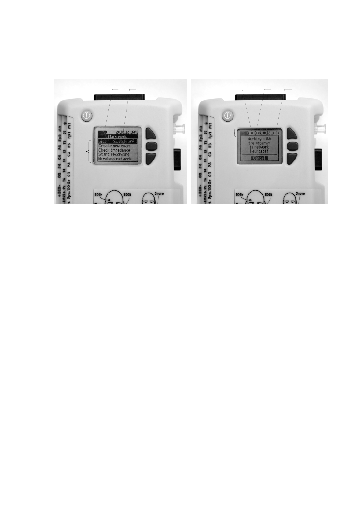
1.6. Display
Electronic unit display space (Fig. 3) is divided into status bar and working area.
14235
Working
area
Status bar
Fig. 3. Electronic unit display.
The status bar is located at the top of the display and contains the following elements
(from left to right):
- battery indicator (1);
- exam recording status indicator (is displayed only during exam performing) (2);
- wireless network module status indicator (is displayed only when the system is con-
nected to the wireless network) (3);
- current date (day, month, two last figures of the year (20)) (4);
- current time (5).
In the remaining part of the display the working area is located. It is meant for display-
ing one of the dialogs to control the system. You can find the detailed information on
working with dialogs in chapter 3 “Proper Use”.

Neuron-Spectrum-AM (Technical Manual)
20
2. Mounting and Installation
2.1. Requirements to the Personnel Conducting
Mounting and Installation
System installation should be carried out by a person who is empowered by the
manufacturer or the technical personnel of the medical institution which is going to
use it. It is necessary to remember that digital system mounting accuracy defines
safety and quality of operation. Further mounting and setting requirements which de-
fine the product safety will be marked by bold and italic fonts in the text.
2.2. Room Selection and Placement
Before mounting and installation of system, it is necessary to select a place for it, tak-
ing into consideration power wiring and protective ground in the room. Please, read
and respect the following requirements and recommendations.
Requirements concerning the room selection and the equipment placement:
Do not place the electronic unit in the immediate vicinity (less than 5 meters) to
short-wave or microwave therapeutic equipment (it can lead to its unstable opera-
tion).
Place the electronic unit on the maximum possible distance from power cables,
switchboards, and different powerful electrical devices which can emit electromag-
netic fields of mains frequency.
The patient environment (within 1.5 meters) should contain only the elec-
tronic units being the medical devices with the required safety level. The fact
is that the safety level of the computer equipment is insufficient for the use in
the patient environment. Hence, a patient must not contact with the metal
parts of computer equipment cases and the personnel must not touch simul-
taneously these parts and patient body. The computer equipment used in the
system should correspond to IEC 60601-1 or be connected via the isolation
transformer (specialized power supply unit – for notebook PC) corresponding
to above-mentioned requirements.
Requirements to mains:
Do not use electric mains in which the neutral conductor and protective
ground are combined. It is strongly prohibited.
Insert the mains plug only in an appropriate mains socket outlet provided
with a protective earth (ground) contact in order to avoid electrical shock.
Before the digital system setting, the electrician must check the quality of
standard tripolar sockets and the integrity of the protective ground circuit.
Table of contents
Other Neurosoft Medical Equipment manuals


