New Eagle Raptor VeeCAN 800 User manual

1
©New Eagle 2017 www.neweagle.net PH: 734.929.4557
Contents
1. Introduction........................................................................................................................................................3
1.1 Motivation ..................................................................................................................................................3
1.2 Setup...........................................................................................................................................................3
Hardware ............................................................................................................................................4
Software .............................................................................................................................................5
2. Building a Model.................................................................................................................................................6
2.1 Getting Started ...........................................................................................................................................6
Creating a New Model ........................................................................................................................6
Performing a Model Update (ctrl+d) ..................................................................................................6
Building a Raptor™ Touchscreen Display Model ...............................................................................6
Programming the Display ...................................................................................................................9
3. Creating a Display............................................................................................................................................ 11
3.1 Screens .................................................................................................................................................... 11
Screen Outputs ................................................................................................................................ 11
Switching Between Screens............................................................................................................. 12
3.2 Drawing.................................................................................................................................................... 12
Drawing Order ................................................................................................................................. 13
Standard Drawing Blocks................................................................................................................. 13
Drawing Images ............................................................................................................................... 15
Clearing Screen Area ....................................................................................................................... 15
Drawing Text Example ..................................................................................................................... 16
3.3 Working with the Touchscreen ............................................................................................................... 19
Touchscreen Calibration.................................................................................................................. 19
Touchscreen Status ......................................................................................................................... 19
Touchscreen Buttons....................................................................................................................... 20
4 Data Logging ……………………………………………………………………………………………………………………………………………. 22
4.1 Under the Hood ………………………………………………………………………………………………………………………………….22
4.2USB Blocks and Read File Example ……………………………………………………..…………………………………………….. 22
4.2.1 USB Status ……………………………………………………………………………………………………………………………….. 25
4.2.2 USB Eject ………………………………………………………………………………………………………………………………….. 25
5. Conclusion ........................................................................................................................................................ 25

2
©New Eagle 2017 www.neweagle.net PH: 734.929.4557
1. Figures
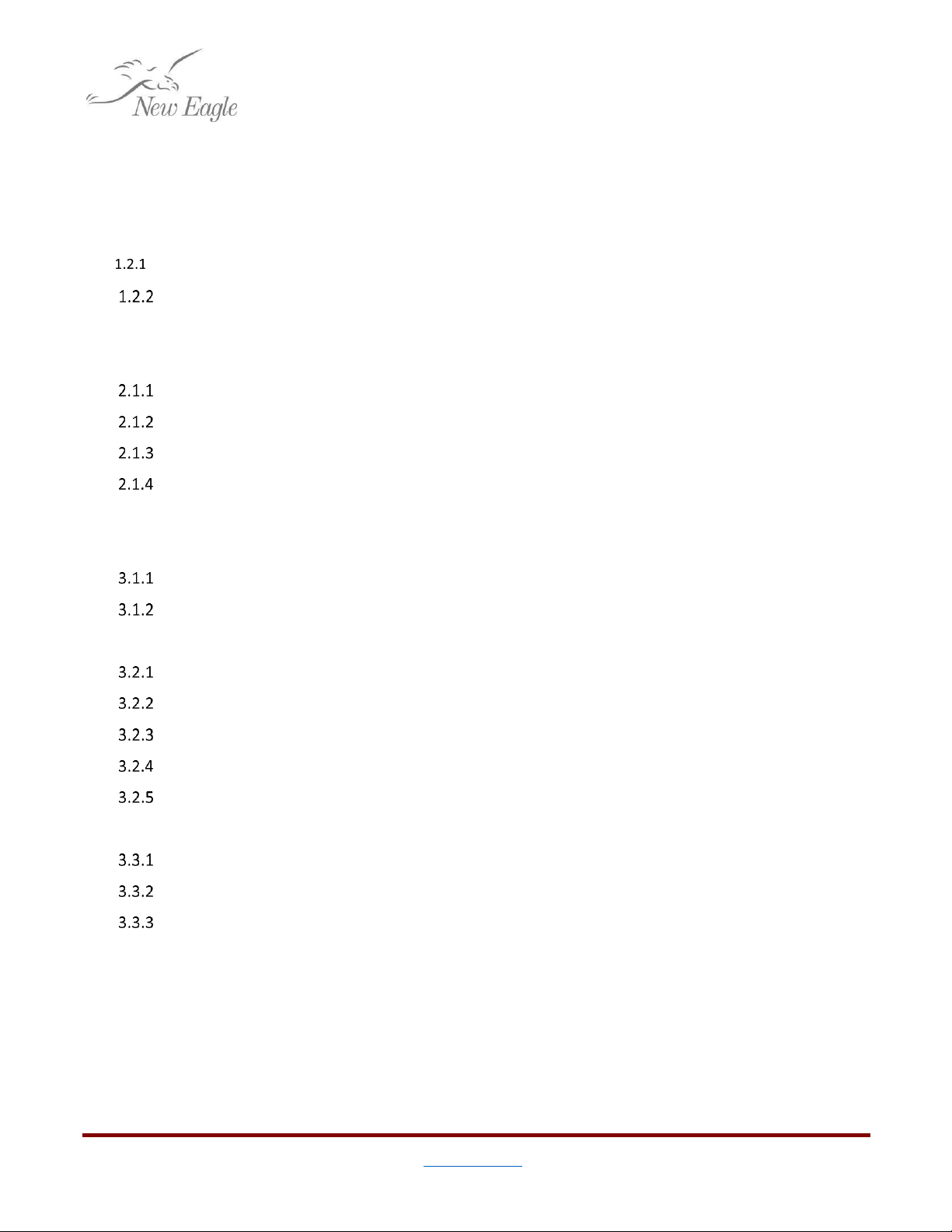
Figure 1.a –The Raptor™Display Library..................................................................................................................3
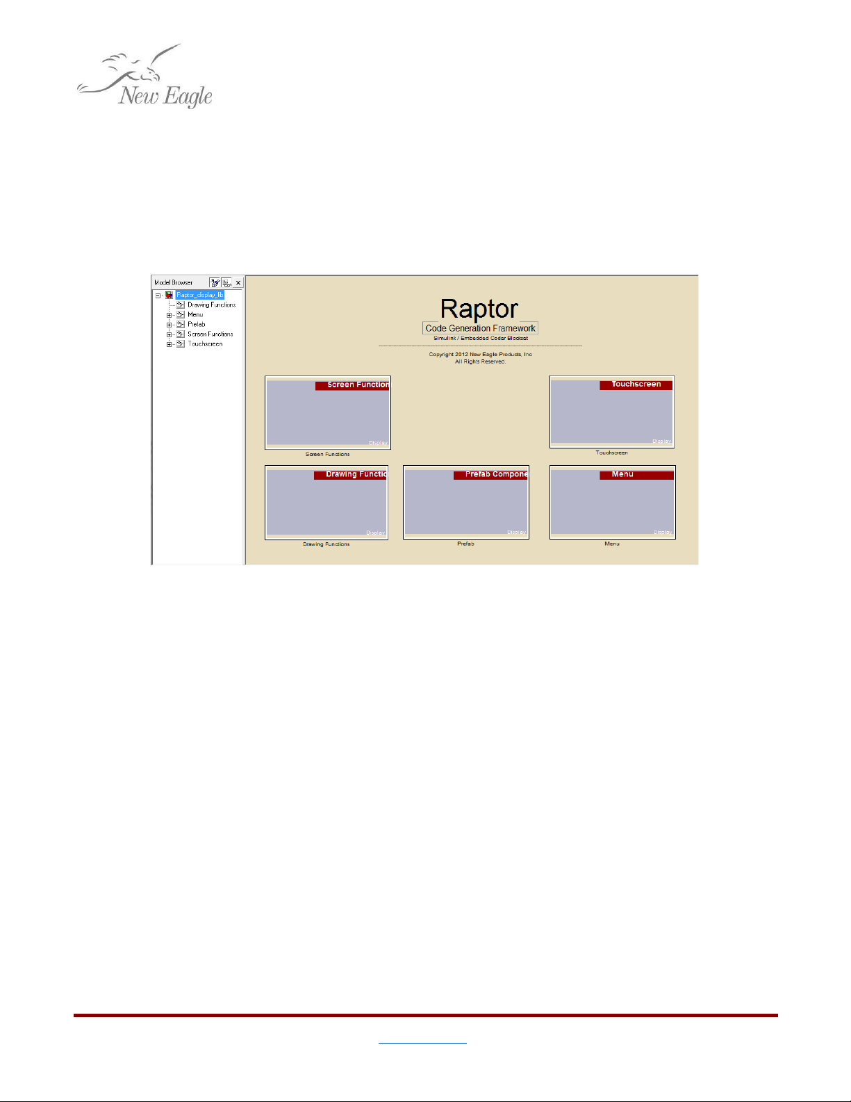
Figure 1.2.1.a –The VeeCAN 800 ...............................................................................................................................4
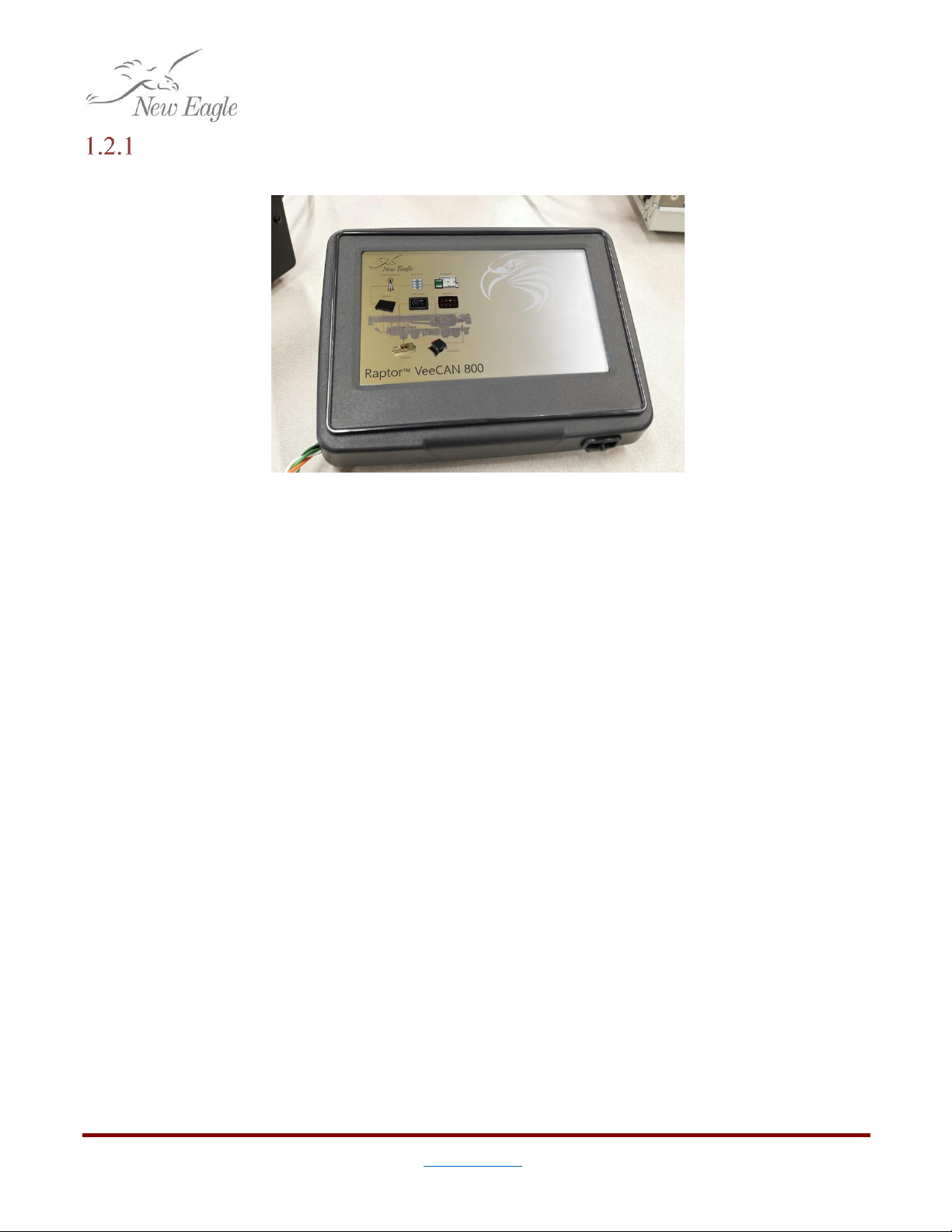
Figure 1.2.2.a –Raptor™ Compatibility Matrix ........................................................................................................5
Figure 2.1.1.a –A Template Touchscreen Display Project .........................................................................................6
Figure 2.1.3.a –Build Configuration Settings in the Target Definition Block ............................................................7
Figure 2.1.3.b –Compiler Settings in the Target Definition Block .............................................................................7
Figures 2.1.3.c & d–An Example of Auto-Run Simulator………………………………………………………………………………………8
Figure 2.1.4.a –USB Drive Inserted in Front of a Raptor™Display ..........................................................................9
Figure 2.1.4.b –Hard Reset Button ..........................................................................................................................10
Figure 3.1.a –Screen Definition ...............................................................................................................................11
Figure 3.1.2.a –Raptor™ Goto Screen Block Called by a Falling Edge Trigger .......................................................12
Figure 3.2.1.a –Previous and Next Ports .................................................................................................................13
Figure 3.2.2.a –Standard Drawing Blocks ...............................................................................................................14
Figure 3.2.3.a –Display Image Blocks .....................................................................................................................15
Figure 3.2.4.a –Block to Clear Screen Area .............................................................................................................15
Figure 3.2.5.a –Raptor™String and Printf blocks ..................................................................................................16
Figure 3.2.5.b –Basic Example to Draw Text ..........................................................................................................17
Figure 3.2.5.c –Drawing text in an Element Block Triggered Subsystem ................................................................17
Figure 3.2.5.d –Comparing Techniques Drawing Text Without an Element Block vs. With One ............................18
Figure 3.3.1.a –Touch Calibration Screen and Recalibrate Screen Block ................................................................19
Figure 3.3.2.a –Display Touchscreen Status Block ..................................................................................................20
Figure 3.3.3.a –Display Touchscreen Button Blocks ...............................................................................................21
Figure 4.1.a –Create_Display Code for CAN Logging ................................................................................................22
Figure 4.1.b—Subsystem2 ………………………………………………………………………………………………………………………..…………23
Figure 4.1.c&d—Path Importance ………………………………………………………………………………………………………………..…….23
Figure 4.2.a –Simple USB Application …………………….................................................................................................24
Figure 4.2.b –Raptor Code for Simple USB Application ……………………......................................................................24
Figure 4.2.1.a –USB Status Block .............................................................................................................................25
Figure 4.2.2.a –USB Eject Block ……………………………................................................................................................25
3
©New Eagle 2017 www.neweagle.net PH: 734.929.4557
1. Introduction
The Raptor™ ™Touchscreen Display is a unique offering from New Eagle. By combining a general
purpose controller and a wide array of communications with a 7-inch touch screen display on top of the Raptor™
model-based development platform, engineers with little to no programming experience have unprecedented
power to create intuitive Man-Machine Interfaces that may either directly control the host system, or
coordinate with other devices.
1.1 Motivation
Figure 1.a –The Raptor™Display Library
The purpose of this paper is to introduce the reader to the Raptor™ Touchscreen Display. A user with no
knowledge of the device should be able to put together a simple but useful application. It is assumed that the
reader has a basic understanding of Matlab, Simulink, and the Raptor™ platform.
1.2 Setup
This guide assumes some knowledge of the Raptor™ platform and model-based development with
Simulink. The minimum requirements to get started are described below:
4
©New Eagle 2017 www.neweagle.net PH: 734.929.4557
Hardware
VeeCAN 800
Figure 1.2.1.a –The VeeCAN 800
Specifications:
7” Resistive Touchscreen Color Display
WVGA 800 x 480 color TFT LCD
Max brightness of 1000 NIT (cd/m2).
Fully waterproof (IP65)
(3) Deutsch 12-pin connectors
2 USB po
rt
s
Freescale iMX 286 processor
Operating Temperature: -30 to +80°C.
Operating Voltage: 10-32 VDC
Available I/O:
14 Analog Inputs
4 Digital Inputs
8 Outputs
2 CAN Channels
Ethernet
2 USB Ports
PC
1 gigahertz (GHz) or faster 32-bit (x86) processor
1 gigabyte (GB) RAM (32-bit)
16 GB available hard disk space
DirectX 9 graphics device with WDDM 1.0 or higher driver.
One USB port and flash drive with 128MB or higher free space
Datalink Adapter (optional)
Though optional, a CAN adapter will allow you to send CAN messages back and forth, and if you
have Raptor-Cal installed take measurements and set adjustments via XCP.
5
©New Eagle 2017 www.neweagle.net PH: 734.929.4557
Software
The Raptor™ platform provides a comprehensive suite of tools to design and program each of the display
devices.
Raptor 2015b and newer no longer support 32-bit MATLAB instillations
Figure 1.2.2.a –Raptor™Compatibility Matrix
Development Environment
Windows 7 or Windows 10
Matlab 2014a or newer
CodeSourcery, Sourcery G++ Lite for ARM GNU Linux
Visual Studio 2010
Visual C++ 2010 SP1 Full
Visual Studio 2010 SP1 Update
.NetFX4.5
Raptor™ 2016b
6
©New Eagle 2017 www.neweagle.net PH: 734.929.4557
2. Building a Model
This guide assumes that the user has installed Raptor™ with a compatible versions of Matlab and
Simulink Coder. For details about compatible versions of Matlab and Raptor™ see section 1.2.2
2.1 Getting Started
Creating a New Model
With Matlab open, enter
‘
raptor_create_touch_display_project('example_project');
’
into the
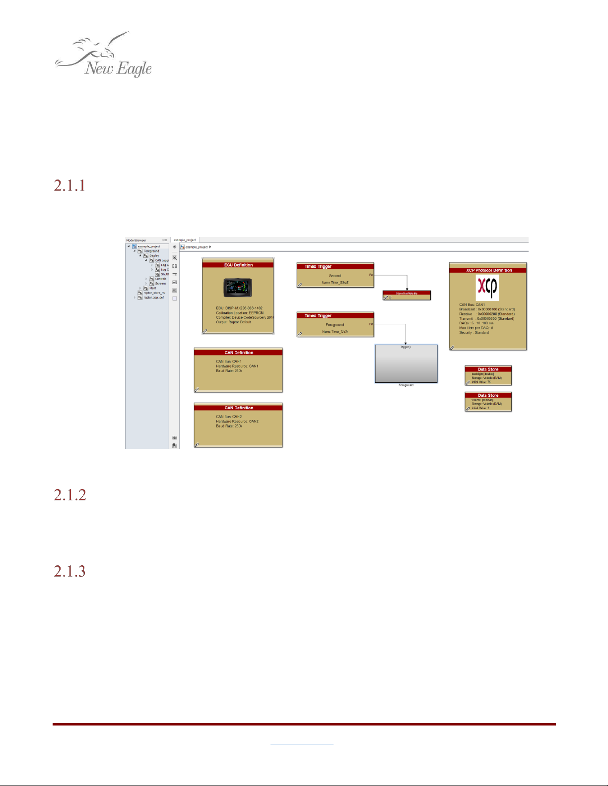
command window. Simulink should open a model like the one shown in figure 2.1.1.a.
Figure 2.1.1.a –A Template Touchscreen Display Project
Performing a Model Update (ctrl+d)
The user may validate a model without executing a full build by performing a Model Update.
This will validate parameters, connections, data types and block-specific constraints to let the user know
if a build will fail, and what can be done to prevent it.
Building a Raptor™ Touchscreen Display Model
In Simulink, a build can be triggered with ctrl+b. This will begin the task of translating blocks
placed in the model into C code and compiling them into either a PC simulator or device binary. By
default the model is configured to generate both. The simulator is useful for debugging, or doing
developing without any display hardware present. Build configuration parameters can be set in the
Target Definition block.
7
©New Eagle 2017 www.neweagle.net PH: 734.929.4557
Configuring the Build
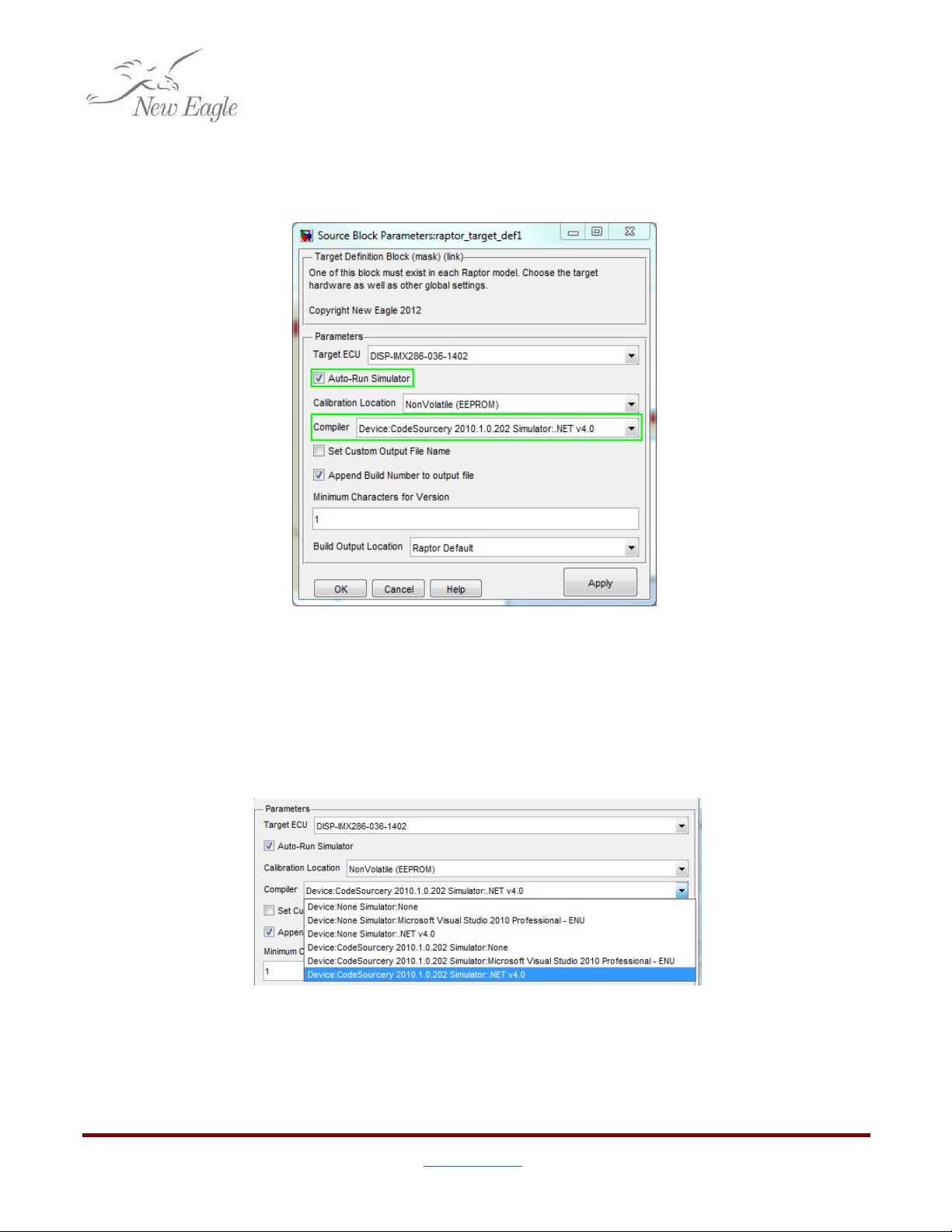
There are two configuration parameters specific to the VeeCAN devices. These can be set by
opening the Target Definition block at the top of the model.
Figure 2.1.3.a –Build Configuration Settings in the Target Definition Block
Compiler
There are actually two parameters to choose for Compiler,
Device
and Simulator. If a compiler is
selected (not set to ‘none’) for device, then a device binary to program a physical VeeCAN 800 will be
generated. If a compiler for
Simulator
is selected, then the same code will be compiled and loaded into
a simulator executable.
Figure 2.1.3.b –Compiler Settings in the Target Definition Block
8
©New Eagle 2017 www.neweagle.net PH: 734.929.4557
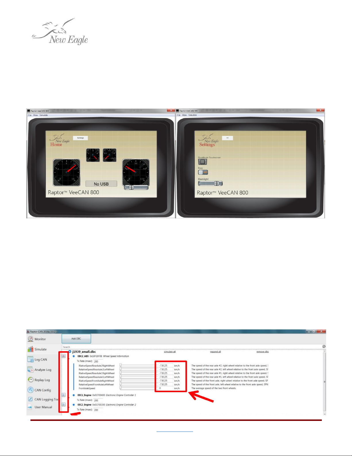
Auto-Run Simulator
Checking Auto-Run
Simulator
will start the simulator executable as soon as the build is finished (if
one has been generated). Here, the user can test functionality of their display by using their mouse as if
it were their finger. You can pause, zoom, grid, and control the fps of the display. These features allow
for additional bug fixing, as well as cosmetic optimization.
Figures 2.1.3.c & d –An Example of Auto-Run Simulator
In addition to simulating the on-screen graphics, users can use a virtual CAN channel to test the
functionality of the display. Open Raptor-CAN and select the simulate tab, notice that the screen will be
blank at first. Next, choose the DBC file you want to simulate by selecting ‘Add DBC’. The messages from
the DBC file will appear, they can be expanded using the ‘+’ icon give the user access to individual signals.
To simulate the messages over the virtual CAN bus, press the play button next to the messages. From
here, the user can adjust the values by using the sliders or typing values in to the text fields on the right,
this will cause the data going into the display to change.
9
©New Eagle 2017 www.neweagle.net PH: 734.929.4557
Programming the Display
By default, Raptor™ builds are output to the
\\ECU\
directory. After a successful build the
output should typically look like,
\\ECU\
|...|-<Project Name>\
|...|...|-<Build Number>\
|...|...|...|- README_HOW_TO_INSTALL.txt
|...|...|...|- <Project Name>_<Build Number>.zip <-- Device Binary
|...|...|...|- Simulator\
|...|...|...|...|- VeeCAN_Simulator.exe <-- VeeCAN Simulator
The contents of the build directory will vary depending on what options were selected in the
target definition block. For instance, a device binary will only be generated if a compiler was selected for
one. For more details see section 2.1.3.
Programming from a USB drive
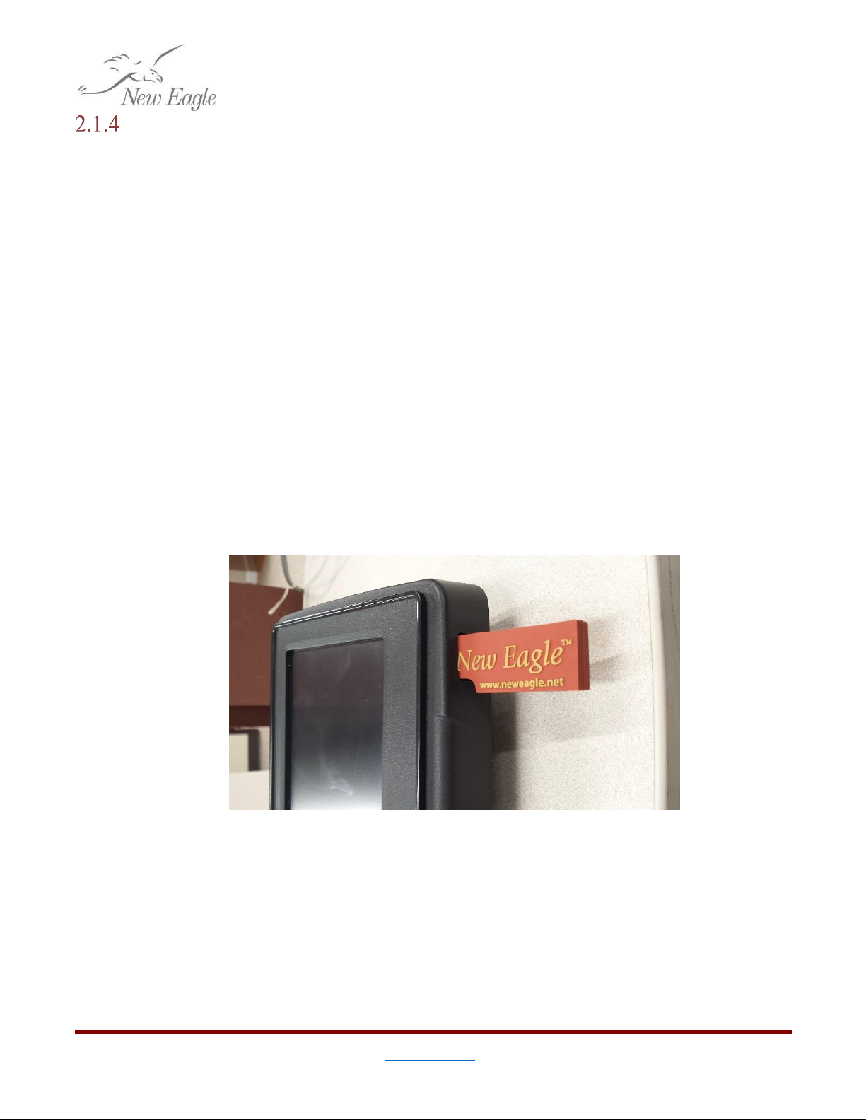
Programming the display requires a USB flash drive. To begin reprogramming, unzip the
contents of the device binary into top level of the flash drive. (ie. so the file system on the flash drive
mirrors what is inside of the .zip file) With the display turned on, insert the flash drive into either USB
port. After a few seconds the device should detect a new program on the USB drive and begin
reprogramming. Follow the instructions on the screen to complete the process.
Figure 2.1.4.a –USB Drive Inserted in Front of a Raptor™ Display
Raptor-Cal
Raptor-Cal allows the user to program the display from a Raptor™ Package file (.rpg), as well
as connect over XCP to probe adjustment and measurement values. For more information on Raptor-Cal
go to www.neweagle.net.
10
©New Eagle 2017 www.neweagle.net PH: 734.929.4557
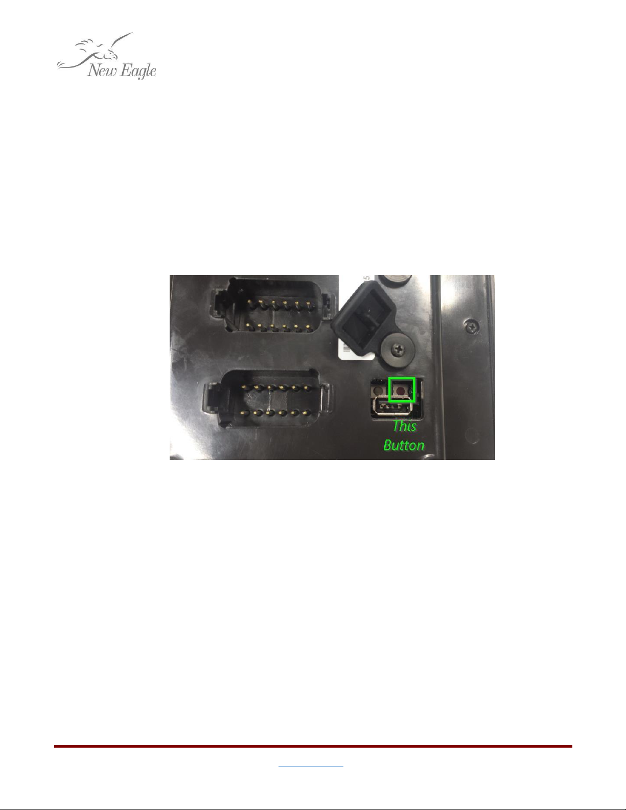
Hard Reset
Occasionally software loaded onto the display may cause it to become inoperable. Sometimes a
startup sequence will put the device into a loop that prevents traditional programming, or a program
may simply crash on startup. When this happens there is a hard-reset option available.
From the hardware manufacturer:
Make sure the power is off then insert the USB Stick into the USB Port. Turn on the power
while simultaneously holding down the small red button right next to the USB port on the
back of the unit. The screen will turn blue and after a few seconds the update process will
begin. There will be on-screen information during the update process. Please remove the USB
Stick when prompted and the target unit will automatically reboot into the new software.
Figure 2.1.4.b –Hard Reset Button
11
©New Eagle 2017 www.neweagle.net PH: 734.929.4557
3. Creating a Display
3.1 Screens
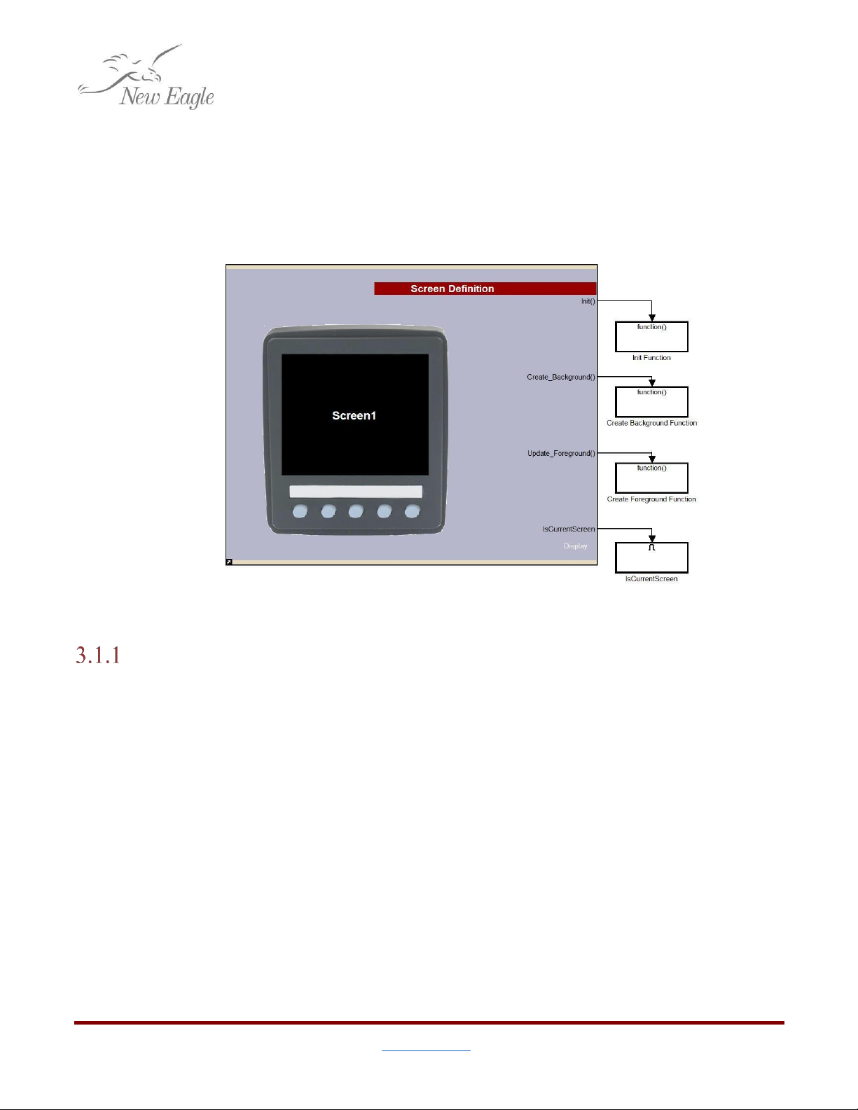
Raptor™ has special blocks for defining graphical output in displays. The main block that organizes the
sequence of drawing UI elements is the Screen Definition block.
Screen Outputs
Figure 3.1.a –Screen Definition
As a rule of thumb,
Create_Background()
and
UpdateForeground()
should only be used for
drawing and display logic. While it’s valid to poll I/O, communications, or work with other pieces of
application logic in these subsystems, it is cleaner to do so in either the
Init()
or IsCurrentScreen
subsystems, using ports as necessary to pipe relevant data back and forth.
Init()
Actions that are executed when a screen is initialized go into the
Init()
function. This
subsystem is called each time the screen is brought up as the current screen.
That is, for two hypothetical screens,
MyScreen1
and MyScreen2, if the application begins on
MyScreen1, switches to MyScreen2, and then switches back to MyScreen1, the
Init()
function will be
called twice; once when the application starts up, and once when switching back from MyScreen2.
Create_Background()
Actions that are executed only when a complete redraw of a screen is required go into the
Create_Background()
function. These because these actions do not happen frequently, only items that
12
©New Eagle 2017 www.neweagle.net PH: 734.929.4557
go into the background such as background images or non-moving parts should go here. This is also a
good place to initialize button definitions.
Update_Foreground()
The display SDK queues foreground drawing tasks and executes them in a tight loop.
Update_Foreground()
is the function that should contain any moving parts or elements that will be
updated live on the screen.
IsCurrentScreen
IsCurrentScreen
is a Boolean output that gets set high when the given screen is current. The
traditional application for this is to attach it to an enabled subsystem allowing everything inside it to
run continuously (free of the display loop.) This is where logic I/O and communications relevant to a
particular screen should go.
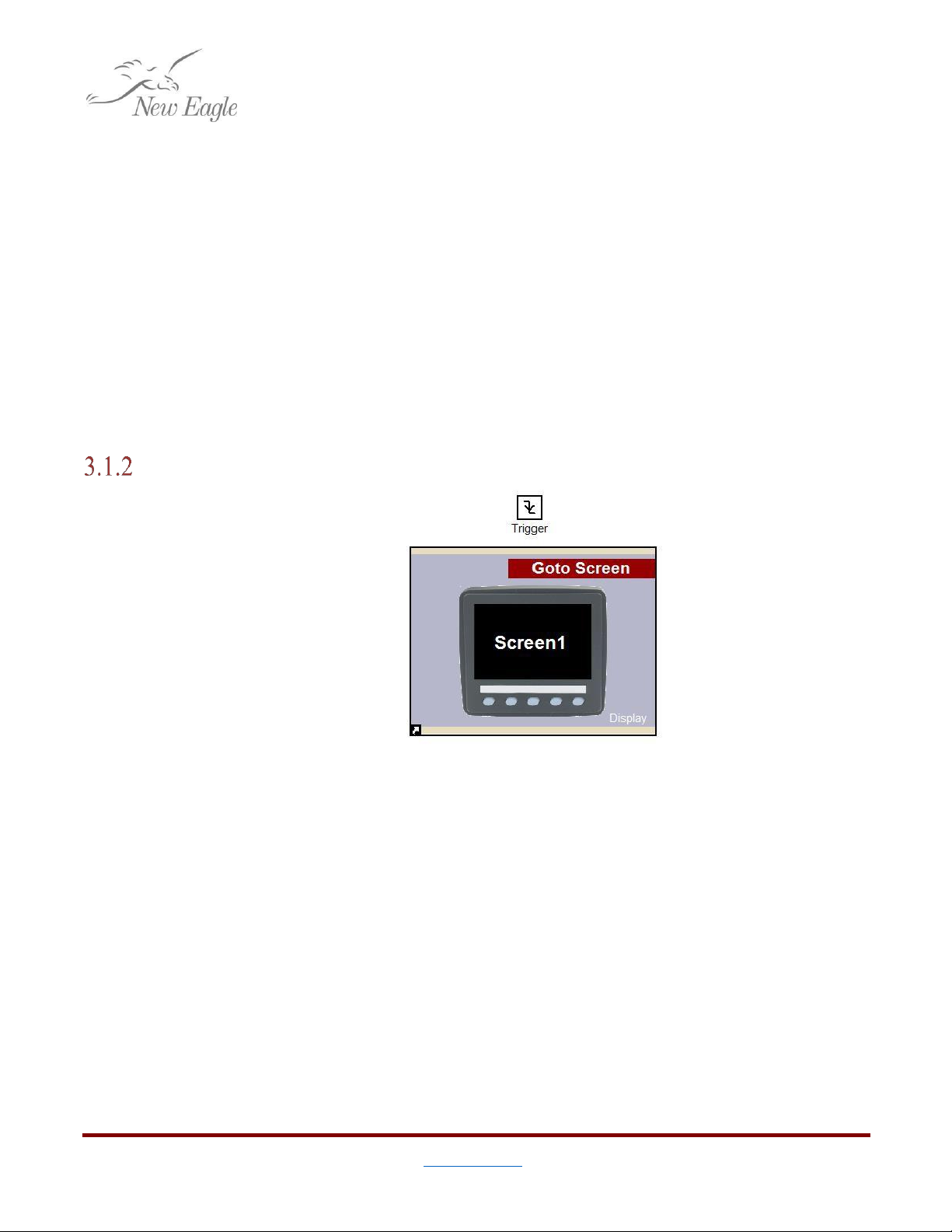
Switching Between Screens
Figure 3.1.2.a –Raptor™Goto Screen Block Called by a Falling Edge Trigger
Switching between screens can be done with the Goto
Screen
block. When executed this block
will switch from the current screen to the specified screen.
Note: When executing this block inside of a Screen function (eg. IsCurrentScreen) it is highly
recommended to place the Goto
Screen
block inside of a triggered subsystem with a falling-edge trigger
to allow the value that triggered the switch to reset before changing screens. This helps to prevent
infinite loops, or being prevented from returning to this screen again
13
©New Eagle 2017 www.neweagle.net PH: 734.929.4557
3.2 Drawing
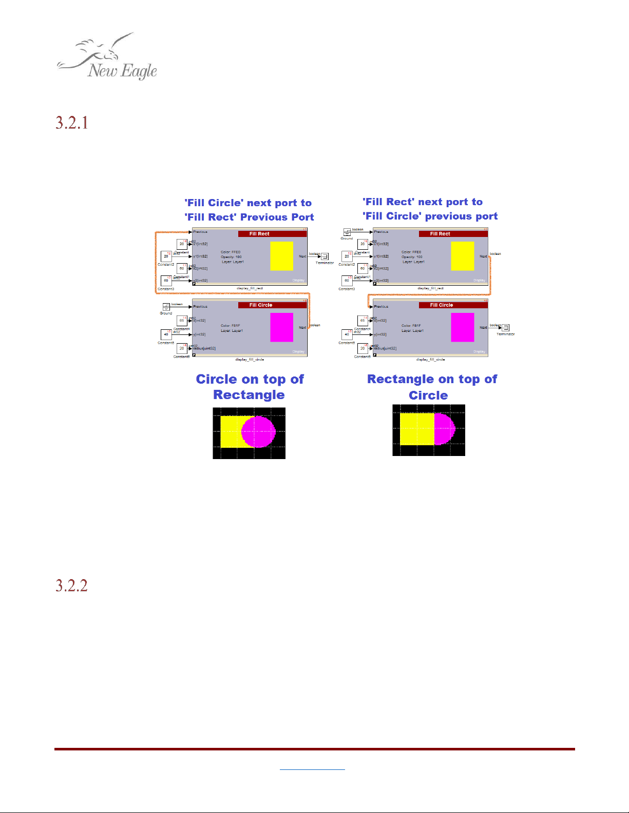
Drawing Order
Most drawing blocks have an option to show ‘previous’ and ‘next’ ports. Next ports output a
Boolean when the drawing block is finished to enable the next block to begin drawing. This ensures
order which is important when an element is meant to overlap another.
Figure 3.2.1.a –Previous and Next Ports
As shown in figure 3.2.1.a, to draw one element on top of another, simply put the next port of
the element that goes on bottom into the previous port of the element that goes on top.
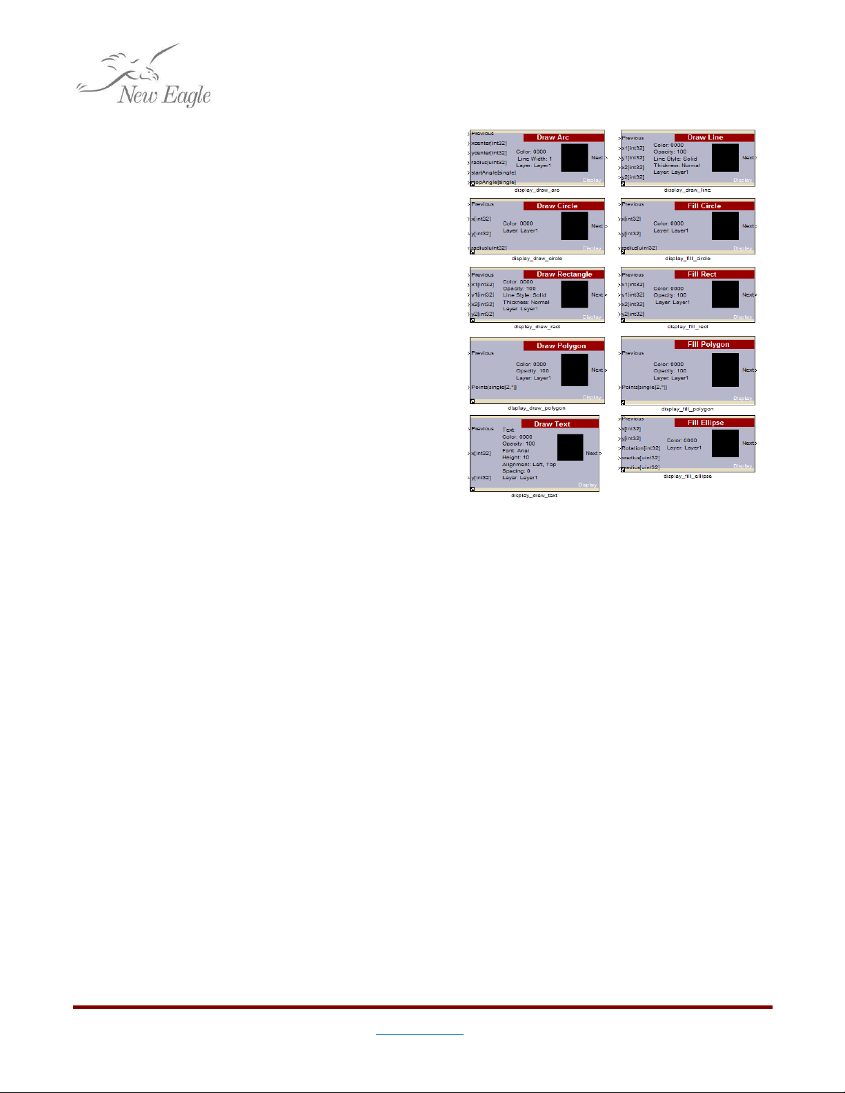
Standard Drawing Blocks
There are ten standard drawing blocks that cover everything from drawing and filling in
differently shaped regions, to writing text to the screen. As an aid, all of these blocks show a sample of
their selected color on the mask when the color value is set directly in the block (as opposed to taken
from a port.)
Draw Arc
Draws an arc of a specified color, thickness, and radius from one angle to another.
14
©New Eagle 2017 www.neweagle.net PH: 734.929.4557
Draw Line
Draws a line of specified color, thickness,
and style from one point to another.
Draw Text
Draws text onto the screen at a specified
location. The block has two ports for X and Y
location. What this location means in terms of
positioning is determined by the horizontal and
vertical alignment parameters which are set in the
mask.
Text may either be directly set in the
block, or taken from a port. For trying to write live
updated text, this can be very useful when used
together with the Raptor™
printf
block. For
more help with drawing text see section 3.2.5.
Draw Circle
Draws a circle of specified color and
thickness around a coordinate location with a
specific radius.
Figure 3.2.2.a –Standard Drawing Blocks
Fill Circle
Fills in a circle area of specified color around a coordinate location with a specific radius.
Draw Rectangle
Draws a rectangle of specified color and thickness between two coordinate locations.
Fill Rectangle
Fills a rectangle area of specified color between two coordinate locations.
Draw Polygon
Draws a polygon of specified color and thickness between a set of ordered pairs
Fill Polygon
Fills a polygon area of specified color between a set of ordered pairs
Fill Ellipse
Fills an ellipse area of specified color about a given center point with a specific x-radius, y-radius,
and rotation.
15
©New Eagle 2017 www.neweagle.net PH: 734.929.4557
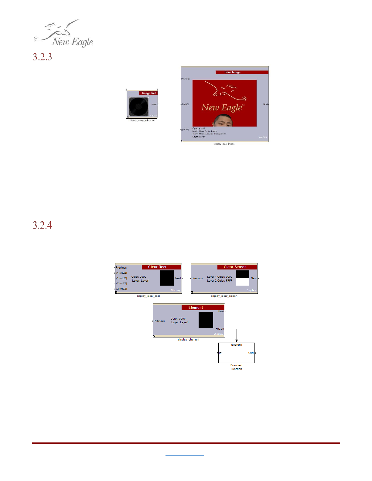
Drawing Images
Figure 3.2.3.a –Display Image Blocks
For outputting images directly onto the display, there is a Draw
Image
block. This block allows for
an image to be placed at a specified coordinate on the screen.
The image my either be specified directly, or through a port with an Image
Ref
block. The Image
Ref
can be useful for using application logic to draw either one image or another.
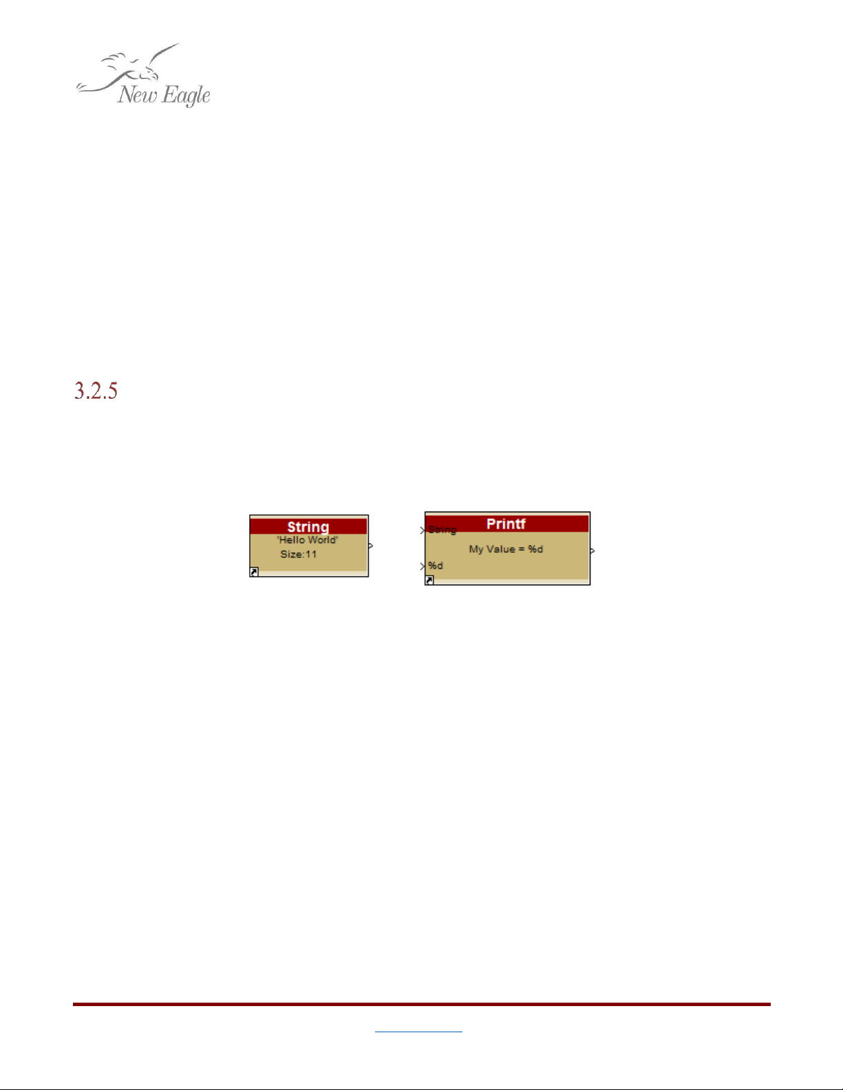
Clearing Screen Area
Sometimes it is helpful to be able to clear an area. There are a few blocks in Raptor™ to help to
help with clearing screen area.
Clear Rect
Figure 3.2.4.a –Block to Clear Screen Area
The Clear
Rect
block works just like the Fill
Rect
block, only rather than covering a particular
area, it is cleared with the background color.
16
©New Eagle 2017 www.neweagle.net PH: 734.929.4557
Clear Screen
The Clear
Screen
block clears an entire screen to show only the background color. A good
application for this is right before a background display gets drawn.
Element
The
Element
block outputs a function call trigger. For elements being actively drawn on the
screen, the
Element
block will first clear the area behind it before drawing. This can be useful for text
being drawn and updated on the screen in the same position.
It should be noted that for elements that will be changing position on the screen, this block is
not a good option, as it will only clear the next position that a block is to be drawn in, leaving an artifact
still from the previous position.
Drawing Text Example
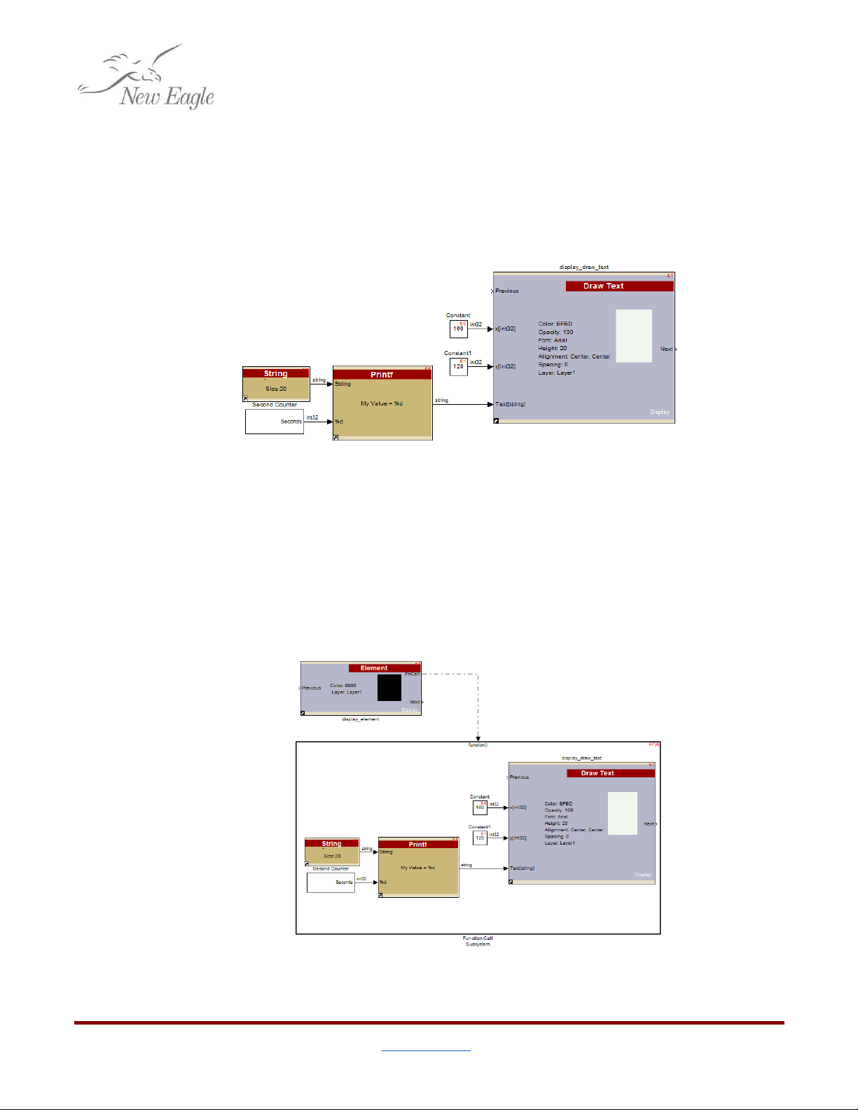
Working with Raptor™ Strings, Printf, etc.
Because the end goal of Simulink is to generate C code, there is no direct notion of a String
object. Raptor™ provides a few blocks to make working with String text easier.
3.2.5.a –Raptor™
String
and
Printf
blocks
The first block Raptor™ provides is the String block. The String block allocates a block of
program memory of a particular character length and if defined, initializes it with a null-terminated
String value. The benefit to this is that a String of text can now be passed around without needing to
explicitly handle it as an array of characters.
The other String block that is commonly useful in display design is the
Printf
block. The Raptor™
Printf
block exposes all the functionality of a C format string in Raptor™. Perhaps the most powerful
feature of this block is that it will read the provided format string, and create input ports for each of the
parameters. The block then outputs the formatted string.
There are a number of other String blocks available in the Raptor™ library as well to convert
Raptor™ Strings to and from arrays, determine length, and even perform a Scanf on a string.
Drawing String Text
Drawing text is fairly straightforward, with a few caveats.
17
©New Eagle 2017 www.neweagle.net PH: 734.929.4557
In this example there’s a Draw
Text
block centered on a point. (i.e. Both horizontal and vertical
alignment are set to center.) There is a
Printf
block with a format string, “My Value = %d”. Raptor™
reads this string and recognizes that there is one integer parameter, and creates an input port on the
block according. Finally, there is an empty Raptor™ String initialized to 20 characters wide to hold the
output value. There is also a custom subsystem that increments a number from zero once a second to
give us some sample data to change live at runtime.
Figure 3.2.5.b –Basic Example to Draw Text
The above example will draw text on the screen, updating the text value every second. The
problem with this approach is that Raptor™will not clear the previous string before drawing the next
one. The result will be a strange overlapped string drawn on the screen.
To updated strings from being written over old ones the easiest technique is to put the live
element being drawn into a function call subsystem triggered by the
Element
block. This will ensure that
the entire area being written is cleared in between each successive redraw.
Figure 3.2.5.c –Drawing Text in an
Element
Block Triggered Subsystem

19
©New Eagle 2017 www.neweagle.net PH: 734.929.4557
3.3 Working with the Touchscreen
What sets this display apart from other display offerings from New Eagle is the 7”resistive touchscreen.
Touchscreen input allows for a wide range of user experience options
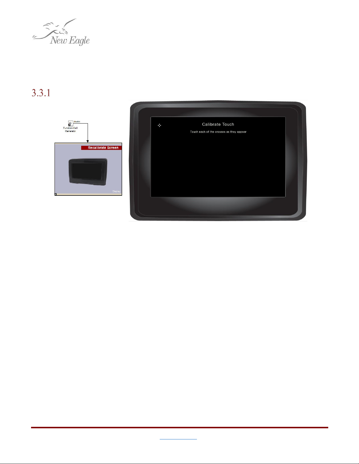
Touchscreen Calibration
Figure 3.3.1.a –Touch Calibration Screen and Recalibrate
Screen
Block
Touchscreen calibration is automatically launched when the device is first turned on after
reprogramming. The application designer can (and should) provide some extra gesture to recalibrate the
display if need be. This can be a long press, a button, or a simple pattern.
If the touchscreen needs to be recalibrated this can be done with the Recalibrate
Screen
block
triggered with a Function call generator. If possible in the application, the gesture to initiate
recalibration should not be dependent on needing to press a particular location on the screen. The
reason for this being that if the touchscreen calibration is very far off the user may not know what
location is actually being clicked in spite of what location is being pressed on the display.
Table of contents
Popular Touchscreen manuals by other brands

Encelium
Encelium KX3 Touchscreen installation instructions

Elo TouchSystems
Elo TouchSystems 2242L user guide

Elo Touch Solutions
Elo Touch Solutions ET1717L user manual

InTouch
InTouch KIO-LITE-156L user manual

Elo TouchSystems
Elo TouchSystems 1000 Series Quick installation guide

SunBriteDS
SunBriteDS DS-3214TSL Operator's manual


